INTRODUCTION AUTOMOBILE ENGINEERING
•Transferir como PPT, PDF•
68 gostaram•9,644 visualizações

The basics of automobile engineering

Recomendados
Mais conteúdo relacionado
Mais procurados
Mais procurados (20)
Semelhante a INTRODUCTION AUTOMOBILE ENGINEERING
Semelhante a INTRODUCTION AUTOMOBILE ENGINEERING (20)
Último
Último (20)
INTRODUCTION AUTOMOBILE ENGINEERING
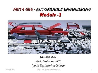
- 1. ME14 606 -ME14 606 - AUTOMOBILE ENGINEERINGAUTOMOBILE ENGINEERING Module -1Module -1 Sukesh O.P.Sukesh O.P. Asst. Professor - MEAsst. Professor - ME Jyothi Engineering CollegeJyothi Engineering College April 11, 2017 ME14 606 /SOP& ARA/APME/JECC 1
- 2. ME14 606 AE Objectives •1 To develop understanding about various automobile components and systems •2 To impart concepts modern automotive controls and safety features April 11, 2017 ME14 606 /SOP& ARA/APME/JECC 2
- 3. MODULE I – Course Plan April 11, 2017 ME14 606 /SOP& ARA/APME/JECC 3 • Introduction – classification of automobiles- automobile terminology. Modern energy systems for automotive application -Electric vehicles – hybrid vehicles – LPG and CNG fueled vehicles – hydrogen fueled vehicles.(basics only) • Chassis and body – body parts, functions, types, material and construction. Engines - component details and materials for cylinder head, cylinder block, piston, piston rings , connecting rod, crank shaft, valve actuating mechanism, VVT(Variable Valve Timing). • Modern Fuel systems: Working and advantages of: Petrol injection – MPFI (Multi Point Fuel Injection), GDI (Gasoline Direct Injection), High pressure pump &Injectors, Diesel Injection- CRDI (Common Rail Direct Injection), Electronic Diesel Control (EDC).
- 4. What is an ‘Automobile’?? • A vehicle producing power within itself for its propulsion is known as a Self propelled vehicle. • Eg. Moped, Scooter, motorcycle, Car, jeep, truck, tractor, ships, aircrafts, rocket etc. • A self propelled vehicle used for transportation of goods & passengers on the ground is called an Automobile. • Different from Aeronautical vehicles (planes, helicopters, rockets) & marine vehicles (ships, boats, submarines) April 11, 2017 ME14 606 /SOP& ARA/APME/JECC 4
- 5. History of Automobiles Captain Nicholas Joseph Cugnot – French Army – built the first self propelled vehicle in 1768-70 April 11, 2017 ME14 606 /SOP& ARA/APME/JECC 5
- 6. First Automobile Cugnot Steam Trolley, Steam Engine powered, 1768 April 11, 2017 ME14 606 /SOP& ARA/APME/JECC 6
- 7. Karl Benz Inventor of the first gasoline powered automobile, 1886 April 11, 2017 ME14 606 /SOP& ARA/APME/JECC 7
- 8. Benz Patent Motorwagen – 1886 – first production car powered by an IC Engine – 954 cc, 2/3 hp or 0.5 kW at 250 rpm April 11, 2017 ME14 606 /SOP& ARA/APME/JECC 8
- 9. April 11, 2017 ME14 606 /SOP& ARA/APME/JECC 9
- 10. Flocken Elektrowagen – 1888 – World’s first electric carApril 11, 2017 ME14 606 /SOP& ARA/APME/JECC 10
- 11. Henry Ford, American Industrialist – Ford Motor Company – founder of the first affordable Motorcar April 11, 2017 ME14 606 /SOP& ARA/APME/JECC 11
- 12. COMPONENTS OF AN AUTOMOBILECOMPONENTS OF AN AUTOMOBILE 1. The Basic structure 2. The Engine 3. The Transmission system 4. The Auxiliaries 5. The Controls 6. The Superstructure April 11, 2017 ME14 606 /SOP& ARA/APME/JECC 12
- 13. COMPONENTS OF AN AUTOMOBILECOMPONENTS OF AN AUTOMOBILE 1.1. The Basic Structure:The Basic Structure: It consists of the frame, the suspension system, axles, wheels and tyres. 1.1. The Engine:The Engine: It provides the motive power for all various functions which the vehicle or any part of it, may be required to perform. The engine for automotive use is IC type. April 11, 2017 ME14 606 /SOP& ARA/APME/JECC 13
- 14. ENGINE April 11, 2017 ME14 606 /SOP& ARA/APME/JECC 14
- 15. COMPONENTS OF AN AUTOMOBILECOMPONENTS OF AN AUTOMOBILE 3.3. The Transmission System:The Transmission System: It consists of a Clutch, a gear box giving four, five or even more different ratios of torque output to torque input, a propeller shaft to transmit the torque output from the gear box to the rear axle and a differential gear to distribute the final torque equally between the driving wheels. April 11, 2017 ME14 606 /SOP& ARA/APME/JECC 15
- 16. Transmission System April 11, 2017 ME14 606 /SOP& ARA/APME/JECC 16
- 17. COMPONENTS OF AN AUTOMOBILECOMPONENTS OF AN AUTOMOBILE 4.4. The Auxiliaries:The Auxiliaries: The Electrical systems. 5.5. The Controls:The Controls: They consists of steering systems and brakes 6.6. The Super Structure:The Super Structure: In those cases where frameless construction is not adopted there must be super structure i.e, the body. April 11, 2017 ME14 606 /SOP& ARA/APME/JECC 17
- 18. Engine SystemsEngine Systems 1. Cooling System 2. Fuel System 3. Lubrication System 4. Ignition System 5. Electrical System April 11, 2017 ME14 606 /SOP& ARA/APME/JECC 18
- 19. Basic Engine Terminology 1. Bore: The inside diameter of the cylinder is called bore 2. Stroke: The linear distance along the cylinder axis between two limiting position s is called stroke. 3. Top Dead Center ( T.D.C.) : The top most position of the piston towards cover end side of the cylinder is called T.D.C. 4. Bottom dead Center ( B.D.C.) : The lowest position of the piston towards the crank end side of the cylinder is called B.D.C. 5. Clearance Volume : The volume contained in the cylinder above the top of the piston , when the piston is at top dead center , is called the clearance volume. 6. Swept Volume: The volume swept through by the piston in moving between T.D.C. and B.D.C, is called swept volume or piston displacement.
- 20. Basic Engine Terminology 7. Compression Ratio: It is the ratio of Total cylinder volume to clearance volume Comp. Ratio 6:1 to 10:1 for Petrol engines 15:1 to 25:1 for Diesel engines Comp. Temp. 250*C for S.I. 600*C for C.I. Comp. Pressure 1 MPa for S.I. 3.5 MPa for C.I.
- 21. Classification Of Automobiles 1.1. Based on PurposeBased on Purpose 1. Passenger Vehicles – Car, Bus, Motorcycle 2. Goods Vehicles – Lorry, truck, Pick up 1.1. Based on CapacityBased on Capacity 1. Heavy Motor Vehicle (HMV) – large trucks, Buses, Tractor 2. Light Motor Vehicle (LMV) – Cars, Jeep, Motor cycles 3. Medium Vehicle – Small trucks, Minibus, Tempo April 11, 2017 ME14 606 /SOP& ARA/APME/JECC 21
- 22. Classification Of AutomobilesClassification Of Automobiles 3. Based on Fuel Source3. Based on Fuel Source 1. Petrol Engine 2. Diesel Engine 3. Gas Vehicles 4. Solar Vehicles 5. Hydrogen Vehicles 6. Electric Vehicles 7. Steam Engine vehicles 8. Hybrid Vehicles 9. Hybrid Electric Vehicles 4.4. Based on Type of TransmissionBased on Type of Transmission 1. Automatic transmission vehicles – mostly American 2. Conventional transmission vehicles – Most Indian Vehicles 3. Semi - Automatic transmission vehicles – mostly British April 11, 2017 ME14 606 /SOP& ARA/APME/JECC 22
- 23. Classification Of AutomobilesClassification Of Automobiles 5. Based on Make5. Based on Make 1. MARUTI SUZUKI 2. HINDUSTAN MOTORS 3. TATA MOTORS 4. MAHINDRA & MAHINDRA 5. TVS MOTORS 6. HERO MOTOCORP 7. ASHOK LEYLAND8. EICHER MOTORS 9. FORCE MOTORS 10. BAJAJ AUTO LTD 11. ROYAL ENFIELD 12.VOLVO, VOLKSWAGEN, MERC BENZ, BMW, CATERPILLAR, BENTLEY, AUDI etc. April 11, 2017 ME14 606 /SOP& ARA/APME/JECC 23
- 24. Classification Of AutomobilesClassification Of Automobiles 6. With respect to the drive6. With respect to the drive 1. Left Hand Drive 2. Right Hand Drive 3. Fluid Drive 4. Front Wheel Drive 5. Rear Wheel Drive 6. All Wheel Drive (AWD or 4WD) 7.7. With respect to the SuspensionWith respect to the Suspension 1. Conventional – Leaf Spring 2. Independent – Coil, Torsion bar, MacPherson Strut April 11, 2017 ME14 606 /SOP& ARA/APME/JECC 24
- 25. Classification Of AutomobilesClassification Of Automobiles 8. With respect to the Type of Engine8. With respect to the Type of Engine 1. Reciprocating – Piston Engines 2. Rotary – Wankel Engine, Gas turbine 9. With respect to the body & doors9. With respect to the body & doors 1. Sedan 2. Hatchback 3. Station Wagon 4. Convertible 5. Sports utility vehicle 6. Multi Utility Vehicle (MUV or MPV) 7. Delivery Vans etc April 11, 2017 ME14 606 /SOP& ARA/APME/JECC 25
- 26. Classification Of AutomobilesClassification Of Automobiles 1010. Based on no. of wheels. Based on no. of wheels 1. Two wheeler 2. Three wheeler 3. Four 4. Six April 11, 2017 ME14 606 /SOP& ARA/APME/JECC 26
- 27. Indian Automakers April 11, 2017 ME14 606 /SOP& ARA/APME/JECC 27
- 28. European Automakers April 11, 2017 ME14 606 /SOP& ARA/APME/JECC 28
- 29. Japanese Automakers April 11, 2017 ME14 606 /SOP& ARA/APME/JECC 29
- 30. American Automakers April 11, 2017 ME14 606 /SOP& ARA/APME/JECC 30
- 31. Italian Automakers April 11, 2017 ME14 606 /SOP& ARA/APME/JECC 31
- 32. French Automakers April 11, 2017 ME14 606 /SOP& ARA/APME/JECC 32
- 33. Swedish Automakers April 11, 2017 ME14 606 /SOP& ARA/APME/JECC 33
- 34. German Automakers April 11, 2017 ME14 606 /SOP& ARA/APME/JECC 34
- 35. Rank of Manufacturer’s by production (2013) 1. TOYOTA – JAPAN 6. NISSAN – JAPAN 2. GENERAL MOTORS – USA 7. FIAT CHRYSLER – ITALY 3. VOLKSWAGEN – GERMANY 8. HONDA – JAPAN 4. HYUNDAI – SOUTH KOREA 9. SUZUKI – JAPAN 5. FORD – USA 10. RENAULT - FRANCE April 11, 2017 ME14 606 /SOP& ARA/APME/JECC 35
- 36. This is a list of the 10 largest manufacturers by production in 2015 Rank Group Country Vehicles 1 Toyota Japan 10,083,831 2 Volkswagen Germany 9,872,424 3 Hyundai South Korea 7,988,479 4 General Motors United States 7,485,587 5 Ford United States 6,396,369 6 Nissan Japan 5,170,074 7 Fiat Chrysler Automobiles Italy/ United States 4,865,233 8 Honda Japan 4,543,838 9 Suzuki Japan 3,034,081 10 Renault France 3,032,652 April 11, 2017 ME14 606 /SOP& ARA/APME/JECC 36
- 37. The Transmission systemThe Transmission system General layout of transmission system of an automobile April 11, 2017 ME14 606 /SOP& ARA/APME/JECC 37
- 38. Functions of transmission systemFunctions of transmission system 1. To disconnect the engine from the road wheels when required. 2. To connect the engine to the driving wheels without shock 3. To vary the leverage between the engine and driving wheels. 4. To reduce the engine speed permanently in a fixed ratio 5. To turn the drive through a right angle. 6. To make provision such that the driving wheels may rotate at different speeds while taking turns. April 11, 2017 ME14 606 /SOP& ARA/APME/JECC 38
- 39. Various components of transmission system 1) Engine 2) Clutch 3) Gearbox 4) Universal joints 5) Differential 6) Wheels 7) Front and rear axles April 11, 2017 ME14 606 /SOP& ARA/APME/JECC 39
- 40. . ClutchClutch : Its purpose is to enable the driver to disconnect the drive from the road wheels instantaneously and to engage drive from the engine to the road wheels gradually while moving the vehicle from rest. GearboxGearbox : The gear box or the transmission provides the necessary leverage variation between the engine and road wheels. DifferentialDifferential : While taking turns, the driving wheels must at different speeds. This is done with the help of differential. April 11, 2017 ME14 606 /SOP& ARA/APME/JECC 40
- 41. Engines April 11, 2017 ME14 606 /SOP& ARA/APME/JECC 41
- 42. April 11, 2017 ME14 606 /SOP& ARA/APME/JECC 42
- 43. Engine & Engine componentsEngine & Engine components April 11, 2017 ME14 606 /SOP& ARA/APME/JECC 43
- 44. April 11, 2017 ME14 606 /SOP& ARA/APME/JECC 44
- 45. Engine & Engine componentsEngine & Engine components 1. Cylinder Block 2. Cylinder head 3. Crankcase 4. piston 5. Piston rings 6. Piston pin 7. Connecting rod 8. Crank shaft 9. Flywheel 10. Valves and valves mechanism 11. Rocker arm 12. Camshaft 13. Accessories: Air cleaner, oil filter, automatic chokes, automatic heat controls. other parts: Spark plug, ignition devices, carburetor April 11, 2017 ME14 606 /SOP& ARA/APME/JECC 45
- 46. Engine componentsEngine components 1.1. Cylinder blockCylinder block It consists of three parts. The cylinder in which the pistons slide up and down. The passages for the flow of cooling water. The bottom of the block supports the crankshaft, oil sump and camshaft. • Various engine accessories & clutch housing are bolted to it. The Cylinder block is usually made from grey cast iron. Sometimes its made with addition of nickel or chromium, Aluminium and Compacted Graphite Iron(CGI) – heavy duty alloy. April 11, 2017 ME14 606 /SOP& ARA/APME/JECC 46
- 47. Engine components :Engine components : 1.Cylinder block1.Cylinder block Cylinder block and crankcase form a single casting (monoblock). It gives a rigid structure and extra strength. The Cylinder block may also have a separate crankcase for the crankshaft.(Individual block) Advantages of Monoblock No water leakage, more rigid Size is reduced, easy water circulation Advantages of Individual block Easy for repairing, less replacement costApril 11, 2017 ME14 606 /SOP& ARA/APME/JECC 47
- 48. Cylinder Block (Monoblock) April 11, 2017 ME14 606 /SOP& ARA/APME/JECC 48
- 49. 2. Cylinder Head2. Cylinder Head The top of the cylinder is covered by a separate cast piece known as the cylinder head. It is bolted to the cylinder block. It is usually made of grey iron or Aluminium alloy. Aluminium has the advantage of light in weight and high heat conductivity. A flat piece of gasket is placed is placed between the cylinder head and block to retain compression in the cylinder and to provide a gas and water tight seal. Gasket made of Copper-asbestos-Copper. •Camshafts, rockers & valves may be carried on the cylinder head. •Water passages may also be provided to cool the valves, the head and the spark plugs. April 11, 2017 ME14 606 /SOP& ARA/APME/JECC 49
- 50. April 11, 2017 ME14 606 /SOP& ARA/APME/JECC 50
- 51. 3.Piston3.Piston Piston helps to convert the chemical energy obtained by the combustion of fuel into useful mechanical power. The purpose of the piston is to provide a means of conveying the expansion of the gases to the crankshaft through the connecting rod. It is provided with piston rings to provide a good seal between the cylinder wall and piston. It has to withstand very high temperatures of combustion. April 11, 2017 ME14 606 /SOP& ARA/APME/JECC 51
- 52. April 11, 2017 ME14 606 /SOP& ARA/APME/JECC 52
- 53. PistonPiston Materials Used Aluminium alloys, Cast steel, Cast Iron or Chrome Nickel April 11, 2017 ME14 606 /SOP& ARA/APME/JECC 53
- 54. Engine components :Engine components : PistonPiston Head or Crown: top of the piston Ring grooves Skirt: parts below the ring grooves Lands: the portion that separates the grooves. The piston must posses the following qualitiesThe piston must posses the following qualities Rigidity to withstand high pressure. Lightness to reduce weight and inertial forces. Good heat conductivity to reduce the risk of detonation Silence in operationApril 11, 2017 ME14 606 /SOP& ARA/APME/JECC 54
- 55. 4.Piston rings4.Piston rings Fine grained alloy cast iron used for the piston rings. Cast Iron plated with Chromium, Cadmium or Tin. Functions:Functions: Prevent the escape of burnt gases from the combustion chamber past the piston (Crank case blow by). Prevent the leakage of oil into the combustion space. Heat from the piston is transmitted to the cylinder via piston rings. April 11, 2017 ME14 606 /SOP& ARA/APME/JECC 55
- 56. Piston Rings April 11, 2017 ME14 606 /SOP& ARA/APME/JECC 56
- 57. 4.Piston rings4.Piston rings a.a. Compression rings:Compression rings: o Prevents the blow by or escape of burnt gases to the crank case. o 2 or 3 compression rings are fitted into the top grooves. o A gap is formed in the ring to impart the property of radial expansion and compression. o This gap is necessary for assembly and renewal of ring o Made from Cast Iron plated with Chromium, Cadmium and Tin. April 11, 2017 ME14 606 /SOP& ARA/APME/JECC 57
- 58. Compression Ring April 11, 2017 ME14 606 /SOP& ARA/APME/JECC 58
- 59. 4.Piston rings4.Piston rings b. Oil Control rings:b. Oil Control rings: oThese rings scrap off excessive oil from the cylinder wall and return it to the oil sump. oThe oil control ring is fitted into the lower groove of the piston. oOil control grooves has a series of slots. These slots transfer the excess oil through the holes in the piston groove to the inside of the piston and to the sump oMade from steel, outer edges of the rings chromium plated April 11, 2017 ME14 606 /SOP& ARA/APME/JECC 59
- 60. April 11, 2017 ME14 606 /SOP& ARA/APME/JECC 60
- 61. 5.Connecting rod5.Connecting rod The connecting rod usually has I-beam cross-section. Small end is connected to the piston pin and big end to the crank pin The function of the connecting rod is to convert linear motion of the piston into rotary motion of the crankshaft. The connecting rod carries the power thrust from piston to the crank pin. So it must be strong, rigid and as light as possible. Always made from steel forgings, in few cases Aluminium alloy is used. April 11, 2017 ME14 606 /SOP& ARA/APME/JECC 61
- 62. 5. Connecting rod5. Connecting rod • Cross section is an “H” or “I” • Types include : a) Plain Rod b) Fork and blade rod c) Master and articulated April 11, 2017 ME14 606 /SOP& ARA/APME/JECC 62
- 63. a) Plain Roda) Plain Rod o Used on inline and opposed engines o Small bushing at piston pin end is pressed in place and reamed to final dimensions o Large end of rod includes a cap, bolts, nuts, and plain bearing inserts o Rods are numbered as to cylinder and for cap-to-rod alignment April 11, 2017 ME14 606 /SOP& ARA/APME/JECC 63
- 64. b) Fork and Blade Connecting Rodb) Fork and Blade Connecting Rod • Used on “V” type engines • One rod inside another allows cylinders to be aligned and to share a common location on the crankshaft April 11, 2017 ME14 606 /SOP& ARA/APME/JECC 64
- 65. Fork and Blade Type C Rod April 11, 2017 ME14 606 /SOP& ARA/APME/JECC 65
- 66. c) Master and Articulating Rodc) Master and Articulating Rod o Used on radial engines o Uses “knuckle pins” to retain articulated rods to master April 11, 2017 ME14 606 /SOP& ARA/APME/JECC 66
- 67. 6. Crank shaft6. Crank shaft It is the 1st part in the power transmission. The reciprocating motion of the piston is converted into rotary motion of the crankshaft with the help of connecting rod. It consists of crankpins, webs, balancing weights and main journals. Big end of connecting rod is connected to the crankpin of the crankshaft. The crank shaft is supported by the main bearings on the main journals. Made of Casting or forging of heat treated alloy steel. April 11, 2017 ME14 606 /SOP& ARA/APME/JECC 67
- 68. Crankshaft April 11, 2017 ME14 606 /SOP& ARA/APME/JECC 68
- 69. Engine components :Engine components : 6.Crank shaft6.Crank shaft April 11, 2017 ME14 606 /SOP& ARA/APME/JECC 69
- 70. Valve Actuating MechanismsValve Actuating Mechanisms To admit the air-fuel mixture in the engine cylinder and to force the exhaust gases out at correct timings, some control system is necessary, which is provided by the valves. The engine valves may be broadly divided into 3 main categories: 1. Poppet valve 2. Sleeve valve 3. Rotary valve A most common type of valve used at present is poppet valve. April 11, 2017 ME14 606 /SOP& ARA/APME/JECC 70
- 71. Valves • Usually made of Austenitic Stainless Steel which is a corrosion & heat resisting material. • Race engines use Beryllium-Copper alloy seats with Titanium valves (21-4N) – 40% lighter than Steel. April 11, 2017 ME14 606 /SOP& ARA/APME/JECC 71
- 72. April 11, 2017 ME14 606 /SOP& ARA/APME/JECC 72
- 73. Poppet ValvePoppet Valve • The valves are operated by cams mounted on a camshaft. • According to the location of the valves, the valve mechanisms are a. Straight poppet valve mechanism b. Overhead poppet valve mechanism c. Overhead camshaft mechanism April 11, 2017 ME14 606 /SOP& ARA/APME/JECC 73
- 74. . • The valve mechanism to operate the valve when it is in the engine block(as in L,T and F- head). a. Straight (or side) poppet valvea. Straight (or side) poppet valve mechanismmechanism April 11, 2017 ME14 606 /SOP& ARA/APME/JECC 74
- 75. April 11, 2017 ME14 606 /SOP& ARA/APME/JECC 75
- 76. b. Overhead poppet valve mechanismb. Overhead poppet valve mechanism • The valve mechanism to operate the valve when it is in the cylinder head( as in I and F head design). • It requires two additional moving parts- the push rod and the rocker arm. As the cam rotates, it lifts the valve tappet. • It actuates the push rod and thereby the rocker arm end pushes the valve stem to open the valve. c April 11, 2017 ME14 606 /SOP& ARA/APME/JECC 76
- 77. Overhead Poppet Valve Mechanism April 11, 2017 ME14 606 /SOP& ARA/APME/JECC 77
- 78. April 11, 2017 ME14 606 /SOP& ARA/APME/JECC 78
- 79. c. Overhead camshaft mechanismc. Overhead camshaft mechanism • In this type, the camshaft is mounted above the valve in the cylinder head. • The cam on the cam shaft operates the valve directly. A small clearance is provided in between the cam and valve cap. • The clearance is adjusted by providing small shims in the bottom of the cap. c April 11, 2017 ME14 606 /SOP& ARA/APME/JECC 79
- 80. April 11, 2017 ME14 606 /SOP& ARA/APME/JECC 80
- 81. SOHC & DOHC April 11, 2017 ME14 606 /SOP& ARA/APME/JECC 81
- 82. April 11, 2017 ME14 606 /SOP& ARA/APME/JECC 82
- 83. Variable Valve Timing (VVT) April 11, 2017 ME14 606 /SOP& ARA/APME/JECC 83
- 84. Variable Valve Timing (VVT) • Variable Valve Timing (VVT) is the process of altering the timing of a valve lift event, and is often used to improve performance, fuel economy or emissions. It is increasingly being used in combination with variable valve lift systems. April 11, 2017 ME14 606 /SOP& ARA/APME/JECC 84
- 85. • 1. Phase changing systems:1. Phase changing systems: With a single camshaft, all the valve events for both intake and exhaust valves are shifted by the same amount, whereas if separate camshafts are used for intake and exhaust valves, such a phase changing system can change the valves events can be changed independently for the intake and the exhaust valves. April 11, 2017 ME14 606 /SOP& ARA/APME/JECC 85
- 86. 2. Profile switching systems:2. Profile switching systems: these can change independently the valve-event timing and the valve lift. There are two camshafts with separate cam profiles. The system enables the valve operation to be switched between these camshafts at a particular engine speed. -High power output -Low emission level April 11, 2017 ME14 606 /SOP& ARA/APME/JECC 86
- 87. 3. Variable event-timing systems:3. Variable event-timing systems: can change both the phase and duration of valve events and can be optimized for different engines speed and load conditions due to which it is obtain: I.Increase in full-load torque. II.Reduction in part-load emissions. III.Fuel economy e.g. decrease of exhaust emissions. April 11, 2017 ME14 606 /SOP& ARA/APME/JECC 87
- 88. 4. Variable lift systems:4. Variable lift systems: the main adv. Of such systems is reducing the pumping losses due to convectional throttle. 5. Electronic valve actuation systems:5. Electronic valve actuation systems: due to their precise control, these have the maximum potential for optimizing the valve events. Besides, all the valve events including the lift csn be directly controlled. April 11, 2017 ME14 606 /SOP& ARA/APME/JECC 88
- 89. Automobile Chassis • Chassis – French term used to denote the main structure of a vehicle • It’s the backbone of the vehicle – made of steel. • All moving parts are fitted to it. • To give it extra strength it is provided with bolted, riveted or welded cross pieces. • All major units required to propel the vehicle, direct its motion, stop it as well as permit to run smoothly over varying road surface is known as chassis. April 11, 2017 ME14 606 /SOP& ARA/APME/JECC 89
- 90. Automobile Chassis • The power unit is connected with the transmission. • The structural frame fitted to the axles through the suspension system carries the power train. • For an automobile to propel safely on the road, the engine, the transmission system, suspension, steering & brakes are included to the basic frame. These units combined together – Chassis. • The body or Cabin is jointed to the cabin by means of bolts & nuts or by welding. April 11, 2017 ME14 606 /SOP& ARA/APME/JECC 90
- 91. April 11, 2017 ME14 606 /SOP& ARA/APME/JECC 91
- 92. Chassis Components • Frame • Front Suspension • Steering Mechanism • Wheels, Tyres and axles – rear & front springs & shock absorbers • Engine, Clutch & Gearbox • Propeller shaft • Radiator • Differential, half shaft & universal joint • Brakes & Braking system • Fuel tanks, pipes & connecting fuel lines. • Battery & electrical system • Silencer • Car Body • Car Body accessories like lights, radio, wiper, mirrors etc. April 11, 2017 ME14 606 /SOP& ARA/APME/JECC 92
- 93. • Fast pick up • Strength & Safety • Durability • Dependability • Ease of control • Quietness • Speed • Power accessibility • Low centre of gravity • Simplicity of lubrication • Economy of operation. Desired qualities of a Chassis April 11, 2017 ME14 606 /SOP& ARA/APME/JECC 93
- 94. body April 11, 2017 ME14 606 /SOP& ARA/APME/JECC 94
- 95. April 11, 2017 ME14 606 /SOP& ARA/APME/JECC 95