SlideShare uma empresa Scribd logo
1 de 179
Ref. Calculation Output
1.0 Analysis and Designof Beam
Chac.Variable Action, QK =3.0 kN/m2
Weight of Concrete = 25kN/m3
Action on Slab
Self-weight = 0.15×25kN/m3 = 3.75kN/m2
Finishes, ceiling and services = 1.5kN/m2
Brick wall = 2.6kN/m2
Chac. Permanent Action, GK = 7.85kN/m2
Ref. Calculation Output
Distribution of Actions from Slabs
Slab1 :
𝐼 𝑦
𝐼𝑥
= 4.675𝑚
2.699𝑚
= 1.732 ˂ 2.0
Slab 2 :
𝐼 𝑦
𝐼𝑥
= 3.802𝑚
3.475𝑚
= 1.094˂ 2.0
Slab 3 :
𝐼 𝑦
𝐼𝑥
= 5.698𝑚
2.939𝑚
= 1.94˂ 2.0
Action from Slab
Slab1 w1GK1 = 0.26×7.85kN/m2×0.803m = 1.639kN/m
w1QK1 = 0.26×3.0kN/m2×0.803m = 0.626kN/m
w2GK2 = 0.40×7.85kN/m2×1.896m = 5.953kN/m
w2QK2 = 0.40 ×3.0kN/m2×1.896m = 2.275kN/m
Slab2 w3GK3 = 0.36×7.85kN/m2×2.939m = 8.306kN/m
w3QK3 = 0.36×3.00kN/m2×2.939m = 3.174kN/m
Two
Way
Slab
Ref. Calculation Output
Action on Beam
Beam Self-weight = 0.20m × (0.5-0.15)m × 25 kN/m3
= 1.75kN/m
Span A – B
Permanent Action, GK
= 6.6825kN/m + kN/m + 1.75kN/m
= 14.5892kN/m
Variable Action, QK
= 2.4300kN/m + 1.7843kN/m = 4.2143N/m
Span B – C
Permanent Action, GK
= 6.1256kN/m + 8.4923kN/m + 3.00kN/m
= 17.6179kN/m
Variable Action, QK
= 2.2275kN/m + 3.0881kN/m = 5.3156kN/m
Ref. Calculation Output
Span C – D
Permanent Action, GK
= 7.9819kN/m + 6.2370kN/m + 3.00kN/m
= 17.2189kN/m
Variable Action, QK
= 2.9025kN/m + 2.2680kN/m = 5.1705kN/m
Span D – E
Permanent Action, GK
= 4.6963kN/m + 7.4003kN/m + 3.00kN/m
= 15.0966kN/m
Variable Action, QK
= 1.7078kN/m + 2.6910kN/m = 4.3988kN/m
Span E – F
Permanent Action, GK
= 5.9214kN/m + 6.4598kN/m + 3.00kN/m
= 15.3812kN/m
Variable Action, QK
= 2.1533kN/m + 2.3490kN/m = 4.5023kN/m
Span F – G
Permanent Action, GK
= 4.9005kN/m + 5.3460kN/m + 3.00kN/m
= 13.2465kN/m
Variable Action, QK
= 1.782kN/m + 1.9440kN/m = 3.7260kN/m
Ref. Calculation Output
Span G – H
Permanent Action, GK
= 8.1675kN/m + 9.9000kN/m + 3.00kN/m
= 21.0675kN/m
Variable Action, QK
= 2.9700kN/m + 3.6000kN/m = 6.5700kN/m
Ref. Calculation Output
6.1 Load Distribution of Beam
Case 1: Maximum Loading
FEM
FEMAB = -FEMBA = −
𝑤𝐿2
12
= −
[1.35 (14.5892 𝑘𝑁 𝑚⁄ )+1.50(4.2143𝑘𝑁 𝑚⁄ )](2.2875𝑚)2
12
= -11.3448 kNm
FEMBC = -FEMCB = −
𝑤𝐿2
12
= −
[1.35 (17.6179 𝑘𝑁 𝑚⁄ )+1.50(5.3156𝑘𝑁 𝑚⁄ )](2.2875𝑚)2
12
= -13.8480 kNm
FEMCD = -FEMDC = −
𝑤𝐿2
12
= −
[1.35 (17.2189 𝑘𝑁 𝑚⁄ )+1.50(5.1705𝑘𝑁 𝑚⁄ )](3.225𝑚)2
12
= -26.8694 kNm
FEMDE = -FEMED = −
𝑤𝐿2
12
= −
[1.35 (15.0966 𝑘𝑁 𝑚⁄ )+1.50(4.3988 𝑘𝑁 𝑚⁄ )](1.725𝑚)2
12
= -6.6899 kNm
FEMEF = -FEMFE = −
𝑤𝐿2
12
= −
[1.35 (15.3812 𝑘𝑁 𝑚⁄ )+1.50(4.5023𝑘𝑁 𝑚⁄ )](2.175𝑚)2
12
= -10.8481 kNm
FEMFG = -FEMGF = −
𝑤𝐿2
12
= −
[1.35 (13.2465 𝑘𝑁 𝑚⁄ )+1.50(3.7260𝑘𝑁 𝑚⁄ )](1.8𝑚)2
12
= -6.3374 kNm
FEMGH = -FEMHG = −
𝑤𝐿2
12
= −
[1.35 (21.0675 𝑘𝑁 𝑚⁄ )+1.50(6.5700𝑘𝑁 𝑚⁄ )](3.0𝑚)2
12
= -28.7221 kNm
Moment Distribution
Mem AB BA BC CB CD DC DE ED EF FE FG GF GH HG
CF 0 0.5 0.5 0.5 0.5 0.5 0.5 0.5 0.5 0.5 0.5 0.5 0.5 0
DF 1 0.5 0.5 0.585 0.415 0.3485 0.6515 0.5577 0.4423 0.4528 0.5472 0.625 0.375 1
FEM -11.3448 11.3448 -13.8480 13.8480 -26.8694 26.8694 -6.6899 6.6899 -10.8481 10.8481 -6.3374 6.3374 -28.7221 28.7221
Dist 11.3448 1.2516 1.2516 7.6175 5.4039 -7.0326 -13.1470 2.3191 1.8392 -2.0425 -2.4683 13.9904 8.3943 -28.7221
Co 0.6258 0 3.8087 0.6258 -3.5163 2.7019 1.1595 -6.5735 -1.0212 0.9196 6.9952 -1.2341 0 4.1971
Dist -0.6258 -1.9044 -1.9044 1.6909 1.1995 -1.3457 -2.5157 4.2356 3.3591 -3.5838 -4.3310 0.7713 0.4628 -4.1971
Co -0.9522 0 0.8455 -0.9522 -0.6729 0.5998 2.1178 -1.2579 -1.7919 1.6796 0.3857 -2.1655 0 0.2314
Dist 0.9522 -0.4227 -0.4227 0.9507 0.6744 -0.9471 -1.7705 1.7009 1.3489 -0.9351 -1.1301 1.3534 0.8121 -0.2314
Co -0.2114 0 0.4753 -0.2114 -0.4735 0.3372 0.8504 -0.8852 -0.4676 0.6745 0.6767 -0.5651 0 0.4060
Dist 0.2114 -0.2377 -0.2377 0.4007 0.2842 -0.4139 -0.7737 0.7545 0.5984 -0.6118 -0.7394 0.3532 0.2119 -0.4060
Co -0.1188 0 0.2003 -0.1188 -0.2069 0.1421 0.3772 -0.3869 -0.3059 0.2992 0.1766 -0.3697 0 0.1059
Dist 0.1188 -0.1002 -0.1002 0.1906 0.1352 -0.1810 -0.3384 0.3864 0.3064 -0.2154 -0.2603 0.2311 0.1386 -0.1059
Co -0.0501 0 0.0953 -0.0501 -0.0905 0.0676 0.1932 -0.1692 -0.1077 0.1532 0.1155 -0.1302 0 0.0693
Dist 0.0501 -0.0476 -0.0476 0.0822 0.0583 -0.0909 -0.1699 0.1544 0.1225 -0.1217 -0.1471 0.0814 0.0488 -0.0693
0 9.8838 -9.8838 24.0739 -24.0739 20.7069 -20.7069 6.9680 -6.9680 7.0638 -7.0638 18.6536 -18.6536 0
Ref. Calculation Output
Uniform Distribution Loading
Loading at Span A – B = [1.35(14.5892kN/m) + 1.50(4.2143kN/m)]
= 26.0169kN/m
Loading at Span B – C = [1.35(17.6179kN/m) + 1.50(5.3156kN/m)]
= 31.7575 kN/m
Loading at Span C – D = [1.35(17.2189kN/m) + 1.50(5.1705kN/m)]
= 31.0013 kN/m
Loading at Span D – E = [1.35(15.0966kN/m) + 1.50(4.3988kN/m)]
= 26.9786 kN/m
Loading at Span E – F = [1.35(15.3812kN/m) + 1.50(4.5023kN/m)]
= 26.9786 kN/m
Loading at Span E – F = [1.35(15.3812kN/m) + 1.50(4.5023kN/m)]
= 27.5181 kN/m
Loading at Span F – G = [1.35(13.2465kN/m) + 1.50(3.7260kN/m)]
= 23.4718 kN/m
Loading at Span G – H = [1.35(21.0675kN/m) + 1.50(6.5700kN/m)]
= 38.2961 kN/m
Ref. Calculation Output
Span A – B
+↻ ∑ 𝑀 𝐵 = 0
= 2.2875𝑚 𝑅 𝐴 − (26.0169 𝑘𝑁 𝑚⁄ )(2.2875𝑚)(
2.2875𝑚
2
) −
0𝑘𝑁𝑚 + 9.8838𝑘𝑁𝑚
RA = 25.436kN
↑ ∑ 𝐹𝑦 = ↓ ∑ 𝐹𝑦
RA - RB1 = 26.0169kN/m (2.2875m)
RB1 = 34.078kN
→ ∑ 𝐻𝐴 = ← ∑ 𝐻 𝐵1
= 0
Ref. Calculation Output
Span B – C
+↻ ∑ 𝑀 𝐶 = 0
= 2.2875𝑚𝑅 𝐵2 −
(31.7575 𝑘𝑁 𝑚⁄ )(2.2875𝑚)(
2.2875𝑚
2
) −
9.8838𝑘𝑁𝑚 + 24.0739𝑘𝑁𝑚
RB2 = 30.119kN
↑ ∑ 𝐹𝑦 = ↓ ∑ 𝐹𝑦
RB2 + RC1 = 31.7575 kN/m (2.2875m)
RC1 = 42.526kN
→ ∑ 𝐻 𝐵2 = ← ∑ 𝐻 𝐶1
= 0
Ref. Calculation Output
Span C – D
+↻ ∑ 𝑀 𝐷 = 0
= 3.225𝑚𝑅 𝐶2 − (31.0013 𝑘𝑁 𝑚⁄ )(3.225𝑚)(
3.225𝑚
2
) −
24.0739𝑘𝑁𝑚 + 20.7069𝑘𝑁𝑚
RC2 = 51.034kN
↑ ∑ 𝐹𝑦 = ↓ ∑ 𝐹𝑦
RC2 + RD1 = 31.0013kN/m (3.225m)
RD1 = 48.945kN
→ ∑ 𝐻 𝐶2 = ← ∑ 𝐻 𝐷1
= 0
Ref. Calculation Output
Span D - E
+↻ ∑ 𝑀 𝐸 = 0
= 1.725𝑚𝑅 𝐷2 − (26.9786 𝑘𝑁 𝑚⁄ )(1.725𝑚)(
1.725𝑚
2
) −
20.7069𝑘𝑁𝑚 + 6.9680𝑘𝑁𝑚
RD2 = 31.234kN
↑ ∑ 𝐹𝑦 = ↓ ∑ 𝐹𝑦
RD2 + RE1 = 26.9786 kN/m (1.725m)
RE1 = 15.304kN
→ ∑ 𝐻 𝐷2 = ← ∑ 𝐻 𝐸1
= 0
Ref. Calculation Output
Span E – F
+↻ ∑ 𝑀 𝐸 = 0
= 2.175𝑚𝑅 𝐸2 − (27.5181 𝑘𝑁 𝑚⁄ )(2.175𝑚)(
2.175𝑚
2
) −
6.9680𝑘𝑁𝑚 + 7.0638𝑘𝑁𝑚
RE2 = 29.882kN
↑ ∑ 𝐹𝑦 = ↓ ∑ 𝐹𝑦
RE2 + RF1 = 27.5181kN/m (2.175m)
RF1 = 29.970kN
→ ∑ 𝐻 𝐸2 = ← ∑ 𝐻 𝐹1
= 0
Ref. Calculation Output
Span F – G
+↻ ∑ 𝑀 𝐹 = 0
= 1.8𝑚𝑅 𝐹2 − (23.4718𝑘𝑁 𝑚⁄ )(1.8𝑚)(
1.8𝑚
2
) −
7.0638𝑘𝑁𝑚 + 18.6536𝑘𝑁𝑚
RF2 = 14.686kN
↑ ∑ 𝐹𝑦 = ↓ ∑ 𝐹𝑦
RF2 + RG1 = 23.4718kN/m (1.8m)
RG1 = 27.563kN
→ ∑ 𝐻 𝐹2 = ← ∑ 𝐻 𝐺1
= 0
Ref. Calculation Output
Span G – H
+↻ ∑ 𝑀 𝐺 = 0
= 3.0𝑚𝑅 𝐺2 − (38.2961 𝑘𝑁 𝑚⁄ )(3.0𝑚)(
3.0𝑚
2
) −
18.6536𝑘𝑁𝑚 + 0𝑘𝑁𝑚
RG2 = 63.662kN
↑ ∑ 𝐹𝑦 = ↓ ∑ 𝐹𝑦
RG2 + RH = 38.2961kN/m (3.0m)
RH = 1.226kN
→ ∑ 𝐻 𝐺2 = ← ∑ 𝐻 𝐻
= 0
Ref. Calculation Output
Summary
At point A,𝑅 𝐴 = 25.436𝑘𝑁
↺ 𝑀𝐴 = 0𝑘𝑁𝑚
At point B,𝑅 𝐵 = 64.197𝑘𝑁
↺ 𝑀 𝐵 = −9.884𝑘𝑁𝑚
↻ 𝑀 𝐵 = +9.884𝑘𝑁𝑚
At point C,𝑅 𝐶 = 93.560𝑘𝑁
↺ 𝑀𝑐 = −24.074𝑘𝑁𝑚
↻ 𝑀𝑐 = +24.074𝑘𝑁𝑚
At point D,𝑅 𝐷 = 80.179𝑘𝑁
↺ 𝑀 𝐷 = −20.707𝑘𝑁𝑚
↻ 𝑀 𝐷 = +20.707𝑘𝑁𝑚
At point E,𝑅 𝐸 = 45.186𝑘𝑁
↺ 𝑀 𝐸 = −6.968𝑁𝑚
↻ 𝑀 𝐸 = +6.968𝑁𝑚
At point F,𝑅 𝐹 = 44.656𝑘𝑁
↺ 𝑀 𝐹 = −7.064𝑘𝑁𝑚
↻ 𝑀 𝐹 = +7.064𝑘𝑁𝑚
At point G,𝑅 𝐺 = 91.225𝑘𝑁
↺ 𝑀 𝐺 = −18.654𝑘𝑁𝑚
↻ 𝑀 𝐺 = +18.654𝑘𝑁𝑚
At point H,𝑅 𝐻 = 51.226𝑘𝑁
↻ 𝑀 𝐻 = 0𝑘𝑁𝑚
Ref. Calculation Output
6.2 Load Distribution of Beam
Case 2: Alternative Loading
FEM
FEMAB = -FEMBA = −
𝑤𝐿2
12
= −
[1.35 (14.5892 𝑘𝑁 𝑚⁄ )+1.50(4.2143𝑘𝑁 𝑚⁄ )](2.2875𝑚)2
12
= -11.3448 kNm
FEMBC = -FEMCB = −
𝑤𝐿2
12
= −
[1.35 (17.6179 𝑘𝑁 𝑚⁄ )](2.2875𝑚)2
12
= -10.3712 kNm
FEMCD = -FEMDC = −
𝑤𝐿2
12
= −
[1.35 (17.2189 𝑘𝑁 𝑚⁄ )+1.50(5.1705𝑘𝑁 𝑚⁄ )](3.225𝑚)2
12
= -26.8694 kNm
FEMDE = -FEMED = −
𝑤𝐿2
12
= =−
[1.35(15.0966 𝑘𝑁 𝑚⁄ )](1.725𝑚)2
12
= -5.0537 kNm
FEMEF = -FEMFE = −
𝑤𝐿2
12
= −
[1.35 (15.3812 𝑘𝑁 𝑚⁄ )+1.50(4.5023𝑘𝑁 𝑚⁄ )](2.175𝑚)2
12
= -10.8481 kNm
FEMFG = -FEMGF = −
𝑤𝐿2
12
= −
[1.35 (13.2465 𝑘𝑁 𝑚⁄ )](1.8𝑚)2
12
= -4.8283 kNm
FEMGH = -FEMHG = −
𝑤𝐿2
12
= −
[1.35 (21.0675 𝑘𝑁 𝑚⁄ )+1.50(6.5700𝑘𝑁 𝑚⁄ )](3.0𝑚)2
12
= -28.7221 kNm
Moment Distribution
Mem AB BA BC CB CD DC DE ED EF FE FG GF GH HG
CF 0.000 0.500 0.500 0.500 0.500 0.500 0.500 0.500 0.500 0.500 0.500 0.500 0.500 0.000
DF 1.000 0.500 0.500 0.585 0.415 0.349 0.652 0.558 0.442 0.453 0.547 0.625 0.375 1.000
FEM -11.3448 11.3448 -10.3712 10.3712 -26.8694 26.8694 -5.0537 5.0537 -10.8481 10.8481 -4.8283 4.8283 -28.7221 28.7221
Dist 11.3448 -0.4868 -0.4868 9.6514 6.8467 -7.6028 -14.2129 3.2316 2.5629 -2.7258 -3.2940 14.9336 8.9602 -28.7221
Co -0.2434 0.0000 4.8257 -0.2434 -3.8014 3.4234 1.6158 -7.1065 -1.3629 1.2814 7.4668 -1.6470 0.0000 4.4801
Dist 0.2434 -2.4129 -2.4129 2.3662 1.6786 -1.7561 -3.2830 4.7233 3.7460 -3.9612 -4.7870 1.0294 0.6176 -4.4801
Co -1.2064 0.0000 1.1831 -1.2064 -0.8781 0.8393 2.3617 -1.6415 -1.9806 1.8730 0.5147 -2.3935 0.0000 0.3088
Dist 1.2064 -0.5915 -0.5915 1.2194 0.8651 -1.1155 -2.0854 2.0200 1.6021 -1.0811 -1.3065 1.4959 0.8976 -0.3088
Co -0.2958 0.0000 0.6097 -0.2958 -0.5578 0.4325 1.0100 -1.0427 -0.5406 0.8010 0.7480 -0.6533 0.0000 0.4488
Dist 0.2958 -0.3049 -0.3049 0.4993 0.3542 -0.5027 -0.9398 0.8830 0.7003 -0.7014 -0.8476 0.4083 0.2450 -0.4488
Co -0.1524 0.0000 0.2497 -0.1524 -0.2514 0.1771 0.4415 -0.4699 -0.3507 0.3501 0.2041 -0.4238 0.0000 0.1225
Dist 0.1524 -0.1248 -0.1248 0.2362 0.1676 -0.2156 -0.4030 0.4577 0.3630 -0.2510 -0.3033 0.2649 0.1589 -0.1225
Co -0.0624 0.0000 0.1181 -0.0624 -0.1078 0.0838 0.2288 -0.2015 -0.1255 0.1815 0.1324 -0.1517 0.0000 0.0795
Dist 0.0624 -0.0591 -0.0591 0.0996 0.0706 -0.1089 -0.2037 0.1824 0.1446 -0.1421 -0.1718 0.0948 0.0569 -0.0795
0.0000 7.3648 -7.3648 22.4829 -22.4829 20.5238 -20.5238 6.0896 -6.0896 6.4726 -6.4726 17.7860 -17.7860 0.0000
Ref. Calculation Output
Uniform Distribution Loading
Loading at Span A – B = [1.35(14.5892kN/m) + 1.50(4.2143kN/m)]
= 26.0169kN/m
Loading at Span B – C = [1.35(17.6179kN/m)]
= 23.7842kN/m
Loading at Span C – D = [1.35(17.2189kN/m) + 1.50(5.1705kN/m)]
= 31.0013 kN/m
Loading at Span D – E = [1.35(15.0966kN/m)]
= 20.3804kN/m
Loading at Span E – F = [1.35(15.3812kN/m) + 1.50(4.5023kN/m)]
= 26.9786 kN/m
Loading at Span E – F = [1.35(15.3812kN/m) + 1.50(4.5023kN/m)]
= 27.5181 kN/m
Loading at Span F – G = [1.35(13.2465kN/m)]
= 17.8828kN/m
Loading at Span G – H = [1.35(21.0675kN/m) + 1.50(6.5700kN/m)]
= 38.2961 kN/m
Ref. Calculation Output
Span A – B
+↻ ∑ 𝑀 𝐵 = 0
= 2.2875𝑚 𝑅 𝐴 − (26.0169 𝑘𝑁 𝑚⁄ )(2.2875𝑚)(
2.2875𝑚
2
) +
7.3648𝑘𝑁𝑚
RA = 26.537kN
↑ ∑ 𝐹𝑦 = ↓ ∑ 𝐹𝑦
RA - RB1 = 26.0169kN/m (2.2875m)
RB1 = 32.976kN
→ ∑ 𝐻𝐴 = ← ∑ 𝐻 𝐵1
= 0
Ref. Calculation Output
Span B – C
+↻ ∑ 𝑀 𝐶 = 0
= 2.2875𝑚𝑅 𝐵2 −
(23.7842𝑘𝑁 𝑚⁄ )(2.2875𝑚)(
2.2875𝑚
2
) − 7.3648𝑘𝑁𝑚 +
22.4829𝑘𝑁𝑚
RB2 = 20.594kN
↑ ∑ 𝐹𝑦 = ↓ ∑ 𝐹𝑦
RB2 + RC1 = 23.7842kN/m (2.2875m)
RC1 = 33.812kN
→ ∑ 𝐻 𝐵2 = ← ∑ 𝐻 𝐶1
= 0
Ref. Calculation Output
Span C – D
+↻ ∑ 𝑀 𝐷 = 0
= 3.225𝑚𝑅 𝐶2 − (31.0013 𝑘𝑁 𝑚⁄ )(3.225𝑚)(
3.225𝑚
2
) −
22.4829𝑘𝑁𝑚 + 20.5238𝑘𝑁𝑚
RC2 = 50.597kN
↑ ∑ 𝐹𝑦 = ↓ ∑ 𝐹𝑦
RC2 + RD1 = 31.0013kN/m (3.225m)
RD1 = 49.382kN
→ ∑ 𝐻 𝐶2 = ← ∑ 𝐻 𝐷1
= 0
Ref. Calculation Output
Span D - E
+↻ ∑ 𝑀 𝐸 = 0
= 1.725𝑚𝑅 𝐷2 − (20.3804 𝑘𝑁 𝑚⁄ )(1.725𝑚)(
1.725𝑚
2
) −
20.5238𝑘𝑁𝑚 + 6.0896𝑘𝑁𝑚
RD2 = 25.946kN
↑ ∑ 𝐹𝑦 = ↓ ∑ 𝐹𝑦
RD2 + RE1 = 20.3804kN/m (1.725m)
RE1 = 9.210kN
→ ∑ 𝐻 𝐷2 = ← ∑ 𝐻 𝐸1
= 0
Ref. Calculation Output
Span E – F
+↻ ∑ 𝑀 𝐸 = 0
= 2.175𝑚𝑅 𝐸2 − (27.5181 𝑘𝑁 𝑚⁄ )(2.175𝑚)(
2.175𝑚
2
) −
6.0896𝑘𝑁𝑚 + 6.4726𝑘𝑁𝑚
RE2 = 9.750kN
↑ ∑ 𝐹𝑦 = ↓ ∑ 𝐹𝑦
RE2 + RF1 = 27.5181kN/m (2.175m)
RF1 = 30.102kN
→ ∑ 𝐻 𝐸2 = ← ∑ 𝐻 𝐹1
= 0
Ref. Calculation Output
Span F – G
+↻ ∑ 𝑀 𝐹 = 0
= 1.8𝑚𝑅 𝐹2 − (17.8828𝑘𝑁 𝑚⁄ )(1.8𝑚)(
1.8𝑚
2
) −
6.4726𝑘𝑁𝑚 + 17.7860𝑘𝑁𝑚
RF2 = 9.809kN
↑ ∑ 𝐹𝑦 = ↓ ∑ 𝐹𝑦
RF2 + RG1 = 17.8828kN/m (1.8m)
RG1 = 22.380kN
→ ∑ 𝐻 𝐹2 = ← ∑ 𝐻 𝐺1
= 0
Ref. Calculation Output
Span G – H
+↻ ∑ 𝑀 𝐺 = 0
= 3.0𝑚𝑅 𝐺2 − (38.2961 𝑘𝑁 𝑚⁄ )(3.0𝑚)(
3.0𝑚
2
) −
17.7860𝑘𝑁𝑚
RG2 = 63.373kN
↑ ∑ 𝐹𝑦 = ↓ ∑ 𝐹𝑦
RG2 + RH = 38.2961kN/m (3.0m)
RH = 51.516kN
→ ∑ 𝐻 𝐺2 = ← ∑ 𝐻 𝐻
= 0
Ref. Calculation Output
Summary
At point A,𝑅 𝐴 = 26.537𝑘𝑁
↺ 𝑀𝐴 = 0𝑘𝑁𝑚
At point B,𝑅 𝐵 = 53.571𝑘𝑁
↺ 𝑀 𝐵 = −7.365𝑘𝑁𝑚
↻ 𝑀 𝐵 = +7.365𝑘𝑁𝑚
At point C,𝑅 𝐶 = 84.409𝑘𝑁
↺ 𝑀𝑐 = −22.483𝑘𝑁𝑚
↻ 𝑀𝑐 = +22.483𝑘𝑁𝑚
At point D,𝑅 𝐷 = 75.328𝑘𝑁
↺ 𝑀 𝐷 = −20.524𝑘𝑁𝑚
↻ 𝑀 𝐷 = +20.524𝑘𝑁𝑚
At point E,𝑅 𝐸 = 38.960𝑘𝑁
↺ 𝑀 𝐸 = −6.090𝑘𝑁𝑚
↻ 𝑀 𝐸 = +6.090𝑁𝑚
At point F,𝑅 𝐹 = 39.911𝑘𝑁
↺ 𝑀 𝐹 = −6.473𝑘𝑁𝑚
↻ 𝑀 𝐹 = +6.473𝑘𝑁𝑚
At point G,𝑅 𝐺 = 85.753𝑘𝑁
↺ 𝑀 𝐺 = −17.786𝑘𝑁𝑚
↻ 𝑀 𝐺 = +17.786𝑘𝑁𝑚
At point H,𝑅 𝐻 = 51.516𝑘𝑁
↻ 𝑀 𝐻 = 0𝑘𝑁𝑚
Ref. Calculation Output
6.3 Load Distribution of Beam
Case 3: Adjacent Loading
FEM
FEMAB = -FEMBA = −
𝑤𝐿2
12
= −
[1.35 (14.5892 𝑘𝑁 𝑚⁄ )](2.2875𝑚)2
12
= -8.5883 kNm
FEMBC = -FEMCB = −
𝑤𝐿2
12
= −
[1.35 (17.6179 𝑘𝑁 𝑚⁄ )+1.50(5.3156𝑘𝑁 𝑚⁄ )](2.2875𝑚)2
12
= -13.8480 kNm
FEMCD = -FEMDC = −
𝑤𝐿2
12
= −
[1.35 (17.2189 𝑘𝑁 𝑚⁄ )+1.50(5.1705𝑘𝑁 𝑚⁄ )](3.225𝑚)2
12
= -26.8694 kNm
FEMDE = -FEMED = −
𝑤𝐿2
12
= =−
[1.35(15.0966 𝑘𝑁 𝑚⁄ )](1.725𝑚)2
12
= -5.0537 kNm
FEMEF = -FEMFE = −
𝑤𝐿2
12
= −
[1.35 (15.3812 𝑘𝑁 𝑚⁄ )+1.50(4.5023𝑘𝑁 𝑚⁄ )](2.175𝑚)2
12
= -10.8481 kNm
FEMFG = -FEMGF = −
𝑤𝐿2
12
= −
[1.35 (13.2465 𝑘𝑁 𝑚⁄ )+1.50(3.7260𝑘𝑁 𝑚⁄ )](1.8𝑚)2
12
= -6.3374 kNm
FEMGH = -FEMHG = −
𝑤𝐿2
12
= −
[1.35 (21.0675 𝑘𝑁 𝑚⁄ )](3.0𝑚)2
12
= -21.3308 kNm
Moment Distribution
Mem AB BA BC CB CD DC DE ED EF FE FG GF GH HG
CF 0 0.5 0.5 0.5 0.5 0.5 0.5 0.5 0.5 0.5 0.5 0.5 0.5 0
DF 1 0.5 0.5 0.585 0.415 0.3485 0.6515 0.5577 0.4423 0.4528 0.5472 0.625 0.375 1
FEM -8.5883 8.5883 -13.8480 13.8480 -26.8694 26.8694 -5.0537 5.0537 -10.8481 10.8481 -6.3374 6.3374 -21.3308 21.3308
Dist 8.5883 2.6299 2.6299 7.6175 5.4039 -7.6028 -14.2129 3.2316 2.5629 -2.0425 -2.4683 9.3709 5.6225 -21.3308
Co 1.3149 0.0000 3.8087 1.3149 -3.8014 2.7019 1.6158 -7.1065 -1.0212 1.2814 4.6855 -1.2341 0.0000 2.8113
Dist -1.3149 -1.9044 -1.9044 1.4546 1.0319 -1.5047 -2.8130 4.5328 3.5949 -2.7018 -3.2651 0.7713 0.4628 -2.8113
Co -0.9522 0.0000 0.7273 -0.9522 -0.7524 0.5159 2.2664 -1.4065 -1.3509 1.7974 0.3857 -1.6325 0.0000 0.2314
Dist 0.9522 -0.3636 -0.3636 0.9972 0.7074 -0.9696 -1.8127 1.5378 1.2196 -0.9885 -1.1946 1.0203 0.6122 -0.2314
Co -0.1818 0.0000 0.4986 -0.1818 -0.4848 0.3537 0.7689 -0.9063 -0.4943 0.6098 0.5102 -0.5973 0.0000 0.3061
Dist 0.1818 -0.2493 -0.2493 0.3900 0.2767 -0.3912 -0.7314 0.7811 0.6195 -0.5071 -0.6128 0.3733 0.2240 -0.3061
Co -0.1246 0.0000 0.1950 -0.1246 -0.1956 0.1383 0.3906 -0.3657 -0.2536 0.3097 0.1867 -0.3064 0.0000 0.1120
Dist 0.1246 -0.0975 -0.0975 0.1874 0.1329 -0.1843 -0.3446 0.3454 0.2739 -0.2248 -0.2716 0.1915 0.1149 -0.1120
Co -0.0487 0.0000 0.0937 -0.0487 -0.0922 0.0665 0.1727 -0.1723 -0.1124 0.1369 0.0958 -0.1358 0.0000 0.0575
Dist 0.0487 -0.0468 -0.0468 0.0824 0.0585 -0.0833 -0.1558 0.1588 0.1259 -0.1054 -0.1273 0.0849 0.0509 -0.0575
0.0000 8.5565 -8.5565 24.5846 -24.5846 19.9097 -19.9097 5.6838 -5.6838 8.4135 -8.4135 14.2435 -14.2435 0.0000
37
Ref. Calculation Output
Uniform Distribution Loading
Loading at Span A – B = [1.35(14.5892kN/m)]
= 19.6954kN/m
Loading at Span B – C = [1.35(17.6179kN/m) + 1.50(5.3156kN/m)]
= 31.7576kN/m
Loading at Span C – D = [1.35(17.2189kN/m) + 1.50(5.1705kN/m)]
= 31.0013 kN/m
Loading at Span D – E = [1.35(15.0966kN/m)]
= 20.3804kN/m
Loading at Span E – F = [1.35(15.3812kN/m) + 1.50(4.5023kN/m)]
= 27.5181kN/m
Loading at Span E – F = [1.35(15.3812kN/m) + 1.50(4.5023kN/m)]
= 27.5181 kN/m
Loading at Span F – G = [1.35(13.2465kN/m) + 1.50(3.7260kN/m)]
= 23.4718kN/m
38
Loading at Span G – H = [1.35(21.0675kN/m)]
= 28.4411kN/m
39
Ref. Calculation Output
Span A – B
+↻
∑ 𝑀 𝐵
= 0
= 2.2875𝑚 𝑅 𝐴 −
(19.6954 𝑘𝑁 𝑚⁄ )(2.2875𝑚)(
2.2875𝑚
2
) − 0𝑘𝑁𝑚 +
8.5565𝑘𝑁𝑚
RA = 18.786kNm
↑ ∑ 𝐹𝑦 = ↓ ∑ 𝐹𝑦
RA - RB1 = 19.6954kN/m (2.2875m)
RB1 = 26.267kN
→ ∑ 𝐻𝐴 = ← ∑ 𝐻 𝐵1
= 0
40
Ref. Calculation Output
Span B – C
+↻ ∑ 𝑀 𝐶 = 0
= 2.2875𝑚𝑅 𝐵2 −
(31.7576𝑘𝑁 𝑚⁄ )(2.2875𝑚)(
2.2875𝑚
2
) −
8.5565𝑘𝑁𝑚 + 24.5846𝑘𝑁𝑚
RB2 = 29.316kN
↑ ∑ 𝐹𝑦 = ↓ ∑ 𝐹𝑦
RB2 + RC1 = 31.7576kN/m (2.2875m)
RC1 = 43.330kN
→ ∑ 𝐻 𝐵2 = ← ∑ 𝐻 𝐶1
= 0
41
Ref. Calculation Output
Span C – D
+↻ ∑ 𝑀 𝐷 = 0
= 3.225𝑚𝑅 𝐶2 − (31.0013 𝑘𝑁 𝑚⁄ )(3.225𝑚)(
3.225𝑚
2
) −
24.5846𝑘𝑁𝑚 + 19.9097𝑘𝑁𝑚
RC2 = 51.439kN
↑ ∑ 𝐹𝑦 = ↓ ∑ 𝐹𝑦
RC2 + RD1 = 31.0013kN/m (3.225m)
RD1 = 48.540kN
→ ∑ 𝐻 𝐶2 = ← ∑ 𝐻 𝐷1
= 0
42
Ref. Calculation Output
Span D - E
+↻ ∑ 𝑀 𝐸 = 0
= 1.725𝑚𝑅 𝐷2 − (20.3804 𝑘𝑁 𝑚⁄ )(1.725𝑚)(
1.725𝑚
2
) −
19.9097𝑘𝑁𝑚 + 5.6838𝑘𝑁𝑚
RD2 = 25.825kN
↑ ∑ 𝐹𝑦 = ↓ ∑ 𝐹𝑦
RD2 + RE1 = 20.3804kN/m (1.725m)
RE1 = 9.331kN
→ ∑ 𝐻 𝐷2 = ← ∑ 𝐻 𝐸1
= 0
43
Ref. Calculation Output
Span E – F
+↻ ∑ 𝑀 𝐸 = 0
= 2.175𝑚𝑅 𝐸2 − (27.5181 𝑘𝑁 𝑚⁄ )(2.175𝑚)(
2.175𝑚
2
) −
5.6838𝑘𝑁𝑚 + 8.4135𝑘𝑁𝑚
RE2 = 28.671kN
↑ ∑ 𝐹𝑦 = ↓ ∑ 𝐹𝑦
RE2 + RF1 = 27.5181kN/m (2.175m)
RF1 = 31.181kN
→ ∑ 𝐻 𝐸2 = ← ∑ 𝐻 𝐹1
= 0
44
Ref. Calculation Output
Span F – G
+↻ ∑ 𝑀 𝐹 = 0
= 1.8𝑚𝑅 𝐹2 − (23.4718𝑘𝑁 𝑚⁄ )(1.8𝑚)(
1.8𝑚
2
) −
8.4135𝑘𝑁𝑚 + 14.2435𝑘𝑁𝑚
RF2 = 17.886kN
↑ ∑ 𝐹𝑦 = ↓ ∑ 𝐹𝑦
RF2 + RG1 = 23.4718kN/m (1.8m)
RG1 = 24.363kN
→ ∑ 𝐻 𝐹2 = ← ∑ 𝐻 𝐺1
= 0
45
Ref. Calculation Output
Span G – H
+↻ ∑ 𝑀 𝐺 = 0
= 3.0𝑚𝑅 𝐺2 − (28.4411 𝑘𝑁 𝑚⁄ )(3.0𝑚)(
3.0𝑚
2
) −
14.2435𝑘𝑁𝑚 + 0𝑘𝑁𝑚
RG2 = 47.410kN
↑ ∑ 𝐹𝑦 = ↓ ∑ 𝐹𝑦
RG2 + RH = 28.4411kN/m (3.0m)
RH = 37.914kN
→ ∑ 𝐻 𝐺2 = ← ∑ 𝐻 𝐻
= 0
46
Ref. Calculation Output
Summary
At point A,𝑅 𝐴 = 18.786𝑘𝑁
↺ 𝑀𝐴 = 0𝑘𝑁𝑚
At point B,𝑅 𝐵 = 55.583𝑘𝑁
↺ 𝑀 𝐵 = −8.557𝑘𝑁𝑚
↻ 𝑀 𝐵 = +8.557𝑘𝑁𝑚
At point C,𝑅 𝐶 = 94.769𝑘𝑁
↺ 𝑀𝑐 = −24.585𝑘𝑁𝑚
↻ 𝑀𝑐 = +24.585𝑘𝑁𝑚
At point D,𝑅 𝐷 = 74.365𝑘𝑁
↺ 𝑀 𝐷 = −19.910𝑘𝑁𝑚
↻ 𝑀 𝐷 = +19.910𝑘𝑁𝑚
At point E,𝑅 𝐸 = 38.002𝑘𝑁
↺ 𝑀 𝐸 = −5.684𝑘𝑁𝑚
↻ 𝑀 𝐸 = +5.684𝑘𝑁𝑚
At point F,𝑅 𝐹 = 49.067𝑘𝑁
↺ 𝑀 𝐹 = −8.413𝑘𝑁𝑚
47
↻ 𝑀 𝐹 = +8.413𝑘𝑁𝑚
At point G,𝑅 𝐺 = 71.773𝑘𝑁
↺ 𝑀 𝐺 = −14.243𝑘𝑁𝑚
↻ 𝑀 𝐺 = +14.243𝑘𝑁𝑚
At point H,𝑅 𝐻 = 37.914𝑘𝑁
↻ 𝑀 𝐻 = 0𝑘𝑁𝑚
48
Ref. Calculation Output
Distribution Factor, DF
KAB = KBA =
4𝐸𝐼
𝐿
=
4𝐸𝐼
2.2875
= 1.7486 EI
KBC = KCB =
4𝐸𝐼
𝐿
=
4𝐸𝐼
2.2875
= 1.7486 EI
KCD = KDC =
4𝐸𝐼
𝐿
=
4𝐸𝐼
3.225
= 1.2403 EI
KDE = KDE =
4𝐸𝐼
𝐿
=
4𝐸𝐼
1.725
= 2.3188 EI
KEF = KF =
4𝐸𝐼
𝐿
49
=
4𝐸𝐼
2.175
= 1.8391 EI
KFG = KGF =
4𝐸𝐼
𝐿
=
4𝐸𝐼
1.8
= 2.2222 EI
KGH = KHG =
4𝐸𝐼
𝐿
=
4𝐸𝐼
3.0
= 1.3333 EI
Ref. Calculation Output
DFAB = 𝐾 𝐴𝐵
𝐾 𝐴𝐵 +0
= 1.7468 𝐸𝐼
1.7468 𝐸𝐼+0
= 1
DFBA = 𝐾 𝐵𝐴
𝐾 𝐵𝐴 + 𝐾 𝐵𝐶
= 1.7468𝐸𝐼
1.7468 𝐸𝐼+1.7468 𝐸𝐼
= 0.5
DFBC = 𝐾 𝐵𝐶
𝐾 𝐵𝐴 + 𝐾 𝐵𝐶
= 1.7468 𝐸𝐼
1.7468 𝐸𝐼+1.7468 𝐸𝐼
= 0.5
DFCB = 𝐾 𝐶𝐵
𝐾 𝐶𝐵 + 𝐾 𝐶𝐷
= 1.7468 𝐸𝐼
1.7468 𝐸𝐼+1.2403 𝐸𝐼
= 0.585
DFCD = 𝐾 𝐶𝐷
𝐾 𝐶𝐵 +𝐾 𝐶𝐷
= 1.2403 𝐸𝐼
1.7468 𝐸𝐼+1.2403 𝐸𝐼
= 0.415
DFDC = 𝐾 𝐷𝐶
𝐾 𝐷𝐶+ 𝐾 𝐷𝐸
= 1.2403 𝐸𝐼
1.2403 𝐸𝐼+2.3188 𝐸𝐼
= 0.348
5
DFDE = 𝐾 𝐷𝐸
𝐾 𝐷𝐶+ 𝐾 𝐷𝐸
= 2.3188 𝐸𝐼
1.2403 𝐸𝐼+2.3188 𝐸𝐼
= 0.651
5
DFED = 𝐾 𝐸𝐷
𝐾 𝐸𝐷 + 𝐾 𝐸𝐹
= 2.3188 𝐸𝐼
2.3188 𝐸𝐼+1.8391 𝐸𝐼
= 0.557
7
DFEF = 𝐾 𝐸𝐹
𝐾 𝐸𝐷 + 𝐾 𝐸𝐹
= 1.8391 𝐸𝐼
2.3188 𝐸𝐼+1.8391 𝐸𝐼
= 0.442
3
DFFE = 𝐾 𝐹𝐸
𝐾 𝐹𝐸+ 𝐾 𝐹𝐺
= 1.8391 𝐸𝐼
1.8391 𝐸𝐼+2.2222 𝐸𝐼
= 0.452
8
DFFG = 𝐾 𝐹𝐺
𝐾 𝐹𝐸+ 𝐾 𝐹𝐺
= 2.2222 𝐸𝐼
1.8391 𝐸𝐼+2.2222 𝐸𝐼
= 0.547
2
50
DFGF = 𝐾 𝐺𝐹
𝐾 𝐺𝐹 + 𝐾 𝐺𝐻
= 2.2222 𝐸𝐼
2.2222 𝐸𝐼+1.3333 𝐸𝐼
= 0.625
DFGH = 𝐾 𝐺𝐻
𝐾 𝐺𝐹 + 𝐾 𝐺𝐻
= 1.3333 𝐸𝐼
2.2222 𝐸𝐼+1.3333 𝐸𝐼
= 0.375
DFHG = 𝐾 𝐻𝐺
𝐾 𝐻𝐺 + 0
= 1.3333 𝐸𝐼
1.3333 𝐸𝐼+0
= 1
51
Ref. Calculation Output
6.3.1 Simply Supported Beam
1. Specification
Effective Span, L = 1.8m
Characteristic Action :
Finishes, gk = 1.5kN/m
Variable, qk = 3.0kN/m
Design life = 50 Years
Fire Resistance = R90
Exposure Classes = XS3
Materials :
Characteristic Strength of Concrete, fck = 30N/mm2
Characteristic Strength of Steel, fyk = 500N/mm2
Characteristic Strength of Link, fyk = 500N/mm2
52
Unit Weight of Reinforced Concrete = 25kN/mm2
Assumed :
Øbar = 16mm
Ølink = 8mm
53
Ref. Calculation Output
2. Size
Overall depth, h = L/13
= 1.8/13
= 0.138462m
= 138.462mm
Width, b = 0.4h
= 0.4(138.4615mm)
= 55.385mm
Use b x h = 200mm x 350mm 200mm
= 70000mm2 350mm
54
Ref. Calculation Output
3. Durability, Fire and Bond Requirements
Min. concrete cover regard to bond, Cmin,b = 20mm
Min. concrete cover regard to durability,
Cmin,dur = 45mm
Min. required axis distance for R90 fire
resistance, asd = 45mm
asd = a + 10 = 55mm
Min. concrete cover regard to fire
Cmin = 𝑎 𝑠𝑑 − ∅𝑙𝑖𝑛𝑘 − ∅ 𝑏𝑎𝑟 2⁄
= 39mm
Allowance in design for deviation, Δ Cdev = 10mm
Nominal cover, Cnom = Cmin + Δ Cdev
= 49mm Cnom
∴ Cnom = 51mm 51mm
4. Loading and Analysis
Loading on Slab 15:
Slab Thickness = 0.16m
Concrete Unit Weight = 25kN/m3
Self-weight = 25kN/m3 × 0.16m = 4.0kN/m
Finishing, ceiling and Services = 1.5kN/m
55
Permanent Action, gk = 5.5kN/m
Variable Action, qk = 3.0kN/m
FS15
ly = 2.4m
lx = 1.8m
𝑙 𝑦
𝑙 𝑥
= 1.33 ˂ 2.0 (2 way slab)
56
Ref. Calculation Output
Loading on Slab 16:
Slab Thickness = 0.21m
Concrete Unit Weight = 25kN/m3
Self-weight = 25kN/m3 ×
0.21m
= 5.25kN/m
Finishing, ceiling and Services = 1.5kN/m
Permanent Action, gk = 6.75kN/m
Variable Action, qk = 3.0kN/m
FS16
ly = 2.4m
lx = 1.8m
𝑙 𝑦
𝑙 𝑥
= 1.33 ˂ 2.0 (2 way slab)
Load on beam 2-3/D-F
57
58
Ref. Calculation Output
Characteristic permanent load, Gk
Beam self-weight,
βvy = 0.36 and 0.33
Beam self-weight
w0 = 0.2m × 0.35m × 25kN/m3
= 1.75 kN/m
w15 = βvynlx
= 0.36 x 5.5kN/m2 x 1.8m
= 3.564kN/m
w16 = βvynlx
= 0.33 x 6.75kN/m2 x 1.2m
= 2.673kN/m
= Brickwall
w1 = 2.6kN/m2 × 3.0m
= 7.8
Total GK = 15.787kN/m
Characteristic variable load, Qk
w15 = βvynlx
= 0.36 x 3.0kN/m2 x 1.8m
= 1.944kN/m
w16 = βvynlx
= 0.33 x 3.0kN/m2 x 1.2m
= 1.188kN/m
59
Total QK = 3.132kNm
60
Ref. Calculation Output
Design action, Wd = 1.35Gk + 1.5Qk Wd
= 1.35(15.787kN/m) + 1.5(3.132kN/m) 26.01
= 26.01 kN/m kN/m
Shear Force, V = 𝑊 𝑑 𝐿
2
V
= 26.01 𝑘𝑁 𝑚⁄ ×1.8𝑚
2
23.410
= 23.410kN kN
Bending Moment, 𝑀 = 𝑊 𝑑 𝐿2
8
M
= (26.01𝑘𝑁 𝑚⁄ )(1.8𝑚)2
8
10.534
= 10.534kNm kNm
61
Ref. Calculation Output
Effective depth
d = h - Cnom - Ølink - Øbar
= 350mm-50mm-8mm-16mm d
= 278mm 278mm
d' = Cnom + Ølink +
∅ 𝑏𝑎𝑟
2
= 36mm
Design bending moment, Med = 7.153kNm
𝐾 = 𝑀
𝑏𝑑2 𝑓 𝑐𝑘
= 10 .534 ×106
𝑁𝑚𝑚2
(200𝑚𝑚 )(278𝑚𝑚)2(30𝑁/𝑚𝑚2 )
= 0.0227
Kbal = 0.167
K < Kbal ; Compression reinforcement is not required
z =
𝑑[0.5 + √0.25 −
𝐾 𝑏𝑎𝑙
1.134
]
z = 0.82𝑑
z = 227.96mm
Area of Tension steel, As
𝐴 𝑠 = 𝐾 𝑏𝑎𝑙 𝑓 𝑐𝑘 𝑏𝑑2
0.87𝑓 𝑦𝑘 𝑧
+ 𝐴 𝑠′
= (0.167)(30𝑁 𝑚𝑚2⁄ )(200𝑚𝑚)(278𝑚𝑚 )2
0.87 (500𝑁 𝑚𝑚2⁄ )(226.32𝑚𝑚)
+ 𝐴 𝑠′
= 780.925mm2
62
Min and max reinforcement area, As,min
𝐴 𝑠,𝑚𝑖𝑛 = 0.26
𝑓𝑐𝑡𝑚
𝑓𝑦𝑘
𝑏𝑑
=
0.26
2.90𝑁 𝑚𝑚2⁄
500𝑁 𝑚𝑚2⁄
𝑏𝑑
= 0.001508 bd
Exceed 0.0013bd; use 0.0015bd
= 83.844mm2
Ref. Calculation Output
As,max = 0.04Ac
= 0.04 × 200mm × 350mm
= 2800mm2
5. Shear Reinforcement
Design shear force, Ved = 23.410kN
Concrete strut capacity
𝑉𝑅𝑑,𝑚𝑎𝑥 = 0.3𝑏 𝑤 𝑑𝑓𝑐𝑘(1−
𝑓 𝑐𝑘
250
)
(𝑐𝑜𝑡𝜃+𝑡𝑎𝑛𝜃)
= 0.3(200𝑚𝑚)(278𝑚𝑚)(30𝑁 𝑚𝑚2⁄ )(1−
30𝑁 𝑚𝑚2⁄
250
)
(𝑐𝑜𝑡𝜃+𝑡𝑎𝑛𝜃)
= 181.962𝑘𝑁 (𝜃 = 22°, 𝑐𝑜𝑡𝜃 = 2.5)
= 264.211𝑘𝑁 (𝜃 = 45°, 𝑐𝑜𝑡𝜃 = 1.0)
Ved < VRd,maxcot 𝜃= 2.5
Ved < VRd,maxcot 𝜃= 1.0
63
∴ 𝜽 < 𝟐𝟐°
𝜃 = 0.5 sin−1
[
𝑉 𝐸𝑑
0.18𝑏 𝑤 𝑑𝑓𝑐𝑘(1−
𝑓 𝑐𝑘
250
)
]
= 0.5 sin−1
[
18.558×10³ 𝑁
0.18(200𝑚𝑚)(278𝑚𝑚)(30𝑁 𝑚𝑚2⁄ )(1−
30𝑁 𝑚𝑚2⁄
250
)
]
= 2.01°
Use 𝜃 = 22°
𝑡𝑎𝑛𝜃 = 0.40, 𝑐𝑜𝑡𝜃 = 2.5
Shear Link,
𝐴 𝑠𝑤
𝑠
=
𝑉 𝐸𝑑
(0.78𝑓𝑦𝑘 𝑑𝑐𝑜𝑡𝜃)
= 23.410×10³ 𝑁
(0.78)(500𝑁 𝑚𝑚2⁄ )(278𝑚𝑚)(2.5)
= 0.0864mm
Try link: H6 𝐴 𝑠𝑤=28.3mm2
Spacing, s = 28.3 𝑚𝑚2
0.0864 𝑚𝑚
= 327.67mm
64
Ref. Calculation Output
Maximum spacing, = 0.75d
Smax = 0.75(278mm)
= 208.5mm
Use: H6 - 200 H6 - 200
Minimum links,
𝐴 𝑠𝑤
𝑠
= 0.08√ 𝑓𝑐𝑘
𝑏 𝑤
𝑓 𝑦𝑘
= 0.08√30 𝑁 𝑚𝑚2⁄
200𝑚𝑚
500𝑁 𝑚𝑚2⁄
= 0.175 mm
Spacing, s = 28.3 𝑚𝑚2
0.175 𝑚𝑚
= 161.454mm < 0.75d
Use: H6 - 175 H6 - 175
Minimum Links,
𝐴 𝑠𝑤
𝑠
= 0.08√ 𝑓𝑐𝑘
𝑏 𝑤
𝑓 𝑦𝑘
= 0.08√30 𝑁 𝑚𝑚2⁄
200𝑚𝑚
500𝑁 𝑚𝑚2⁄
= 0.175mm
Spacing, s = 28.3mm2/0.175mm
= 161.464mm ˂ 0.75d
Use: H6 - 175
Shear resistance of minimum links
65
𝑉 𝑚𝑖𝑛 =
𝐴 𝑠𝑤
𝑠
(0.78𝑓𝑦𝑘 𝑑𝑐𝑜𝑡𝜃)
= 28.3𝑚𝑚2
200 𝑚𝑚
(0.78)(500𝑁 𝑚𝑚2⁄ )(278𝑚𝑚)(2.5)
= 43.833kN
66
Ref. Calculation Output
Link Arrangement
67
Ref. Calculation Output
6. Deflection
Percentage of required tension reinforcement,
𝜌
=
𝐴 𝑠,𝑟𝑒𝑞
𝑏𝑑
= 775.307𝑚𝑚2
(200𝑚𝑚)(278𝑚𝑚)
= 0.01405
Reference reinforcement ratio,
𝜌°
= √ 𝑓𝑐𝑘 × 10−3
= √30 𝑁 𝑚𝑚2⁄ × 10−3
= 0.00548
Percentage of required compression reinforcement,
𝜌′ = 0
𝜌 > 𝜌° ; Use equation:
𝑙
𝑑
= 𝐾[11 + 1.5√ 𝑓𝑐𝑘
𝜌°
𝜌−𝜌′ +
1
12
√ 𝑓𝑐𝑘√
𝜌′
𝜌°
𝑙
𝑑
= 1.0[11+ 1.5√30 𝑁 𝑚𝑚2⁄
0.00548
0.01405−0
+
1
12
√30 𝑁 𝑚𝑚2⁄ √
0
0.00548
]
𝑙
𝑑
= 1.0[11+ 0.5549+ 0]
𝑙
𝑑
= 11.555
Modification factor less than 7m = 1.00
Modification factor for steel area provided,
=
𝐴 𝑠,𝑝𝑟𝑜𝑣
𝐴 𝑠,𝑟𝑒𝑞
=
943𝑚𝑚2
780.925𝑚𝑚2
68
= 1.208 <1.5 OK!
Allowable span effective depth ratio = (l/d) allowable
= 11.555 × 1.208 × 1.00
= 13.954
Actual Span-effective depth, (l/d)
actual
=
1800 𝑚𝑚
278 𝑚𝑚
= 6.475 < (l/d) allowable OK!
Ref. Calculation Output
7. Cracking
Limiting crack width, wmax = 0.3mm
Steel stress,
𝑓𝑠
= 𝑓𝑦𝑘
1.15
[
𝐺 𝑘+0.3𝑄 𝑘
1.35𝐺 𝑘+1.5𝑄 𝑘
]
1
𝛿
= 500
1.15
[
9.75+0.3(3.0)
1.35(9.75)+1.5(3.0)
]1.0
= 288.813N/mm2
EC2: Max allowable bar spacing = 100mm
Table
4.2
69
Bar spacing,
S
= 200mm- 2(50mm) -2(6mm)-16mm
= 72mm < 100mm OK!
8. Detailing
70
Ref. Calculation Output
5.4.2 Continuous Beam
1. Specification
Span AB
Effective Span, L = 2.2875m
Dimension
Width = 300mm
Depth = 400mm
Characteristic Load
Permanent Loading, GK = 14.5892kN/m
Variable Loading, QK = 4.2143kN/m
Design life = 50 Years
Fire Resistance = R120
Exposure Cement = XS3
Materials:
Unit Weight of Concrete = 25kN/m3
Characteristic strength of concrete, fck = 30N/mm2
Characteristic strength of steel, fyk = 500N/mm2
Characteristic strength of link, fyk = 500Nmm2
Assumed
∅ 𝑏𝑎𝑟 1 = 12mm
∅ 𝑏𝑎𝑟 2 = 8mm
71
∅𝑙𝑖𝑛𝑘 = 6mm
72
Ref. Calculation Output
Span BC
Effective Span, L = 2.2875m
Dimension
Width = 300mm
Depth = 400mm
Characteristic Load
Permanent Loading, GK = 17.6179kN/m
Variable Loading, QK = 5.3156kN/m
Design life = 50 Years
Fire Resistance = R120
Exposure Cement = XS3
Materials:
Unit Weight of Concrete = 25kN/m3
Characteristic strength of concrete, fck = 30N/mm2
Characteristic strength of steel, fyk = 500N/mm2
Characteristic strength of link, fyk = 500Nmm2
Assumed
∅ 𝑏𝑎𝑟 1 = 12mm
∅ 𝑏𝑎𝑟 2 = 8mm
∅𝑙𝑖𝑛𝑘 = 6mm
73
74
Ref. Calculation Output
Span CD
Effective Span, L = 3.225m
Dimension
Width = 300mm
Depth = 400mm
Characteristic Load
Permanent Loading, GK = 17.2189kN/m
Variable Loading, QK = 5.1705kN/m
Design life = 50 Years
Fire Resistance = R120
Exposure Cement = XS3
Materials:
Unit Weight of Concrete = 25kN/m3
Characteristic strength of concrete, fck = 30N/mm2
Characteristic strength of steel, fyk = 500N/mm2
Characteristic strength of link, fyk = 500Nmm2
Assumed
∅ 𝑏𝑎𝑟 1 = 12mm
∅ 𝑏𝑎𝑟 2 = 8mm
∅𝑙𝑖𝑛𝑘 = 6mm
75
76
Ref. Calculation Output
Span DE
Effective Span, L = 1.725m
Dimension
Width = 300mm
Depth = 400mm
Characteristic Load
Permanent Loading, GK = 15.0966kN/m
Variable Loading, QK = 4.3988kN/m
Design life = 50 Years
Fire Resistance = R120
Exposure Cement = XS3
Materials:
Unit Weight of Concrete = 25kN/m3
Characteristic strength of concrete, fck = 30N/mm2
Characteristic strength of steel, fyk = 500N/mm2
Characteristic strength of link, fyk = 500Nmm2
Assumed
∅ 𝑏𝑎𝑟 1 = 12mm
∅ 𝑏𝑎𝑟 2 = 8mm
∅𝑙𝑖𝑛𝑘 = 6mm
77
78
Ref. Calculation Output
Span EF
Effective Span, L = 2.175m
Dimension
Width = 300mm
Depth = 400mm
Characteristic Load
Permanent Loading, GK = 15.3812kN/m
Variable Loading, QK = 4.5023kN/m
Design life = 50 Years
Fire Resistance = R120
Exposure Cement = XS3
Materials:
Unit Weight of Concrete = 25kN/m3
Characteristic strength of concrete, fck = 30N/mm2
Characteristic strength of steel, fyk = 500N/mm2
Characteristic strength of link, fyk = 500Nmm2
Assumed
∅ 𝑏𝑎𝑟 1 = 12mm
∅ 𝑏𝑎𝑟 2 = 8mm
∅𝑙𝑖𝑛𝑘 = 6mm
79
80
Ref. Calculation Output
Span FG
Effective Span, L = 1.8m
Dimension
Width = 300mm
Depth = 400mm
Characteristic Load
Permanent Loading, GK = 13.2465kN/m
Variable Loading, QK = 3.7260kN/m
Design life = 50 Years
Fire Resistance = R120
Exposure Cement = XS3
Materials:
Unit Weight of Concrete = 25kN/m3
Characteristic strength of concrete, fck = 30N/mm2
Characteristic strength of steel, fyk = 500N/mm2
Characteristic strength of link, fyk = 500Nmm2
Assumed
∅ 𝑏𝑎𝑟 1 = 12mm
∅ 𝑏𝑎𝑟 2 = 8mm
∅𝑙𝑖𝑛𝑘 = 6mm
81
82
Ref. Calculation Output
Span GH
Effective Span, L = 3.0m
Dimension
Width = 300mm
Depth = 400mm
Characteristic Load
Permanent Loading, GK = 21.0675kN/m
Variable Loading, QK = 6.570kN/m
Design life = 50 Years
Fire Resistance = R120
Exposure Cement = XS3
Materials:
Unit Weight of Concrete = 25kN/m3
Characteristic strength of concrete, fck = 30N/mm2
Characteristic strength of steel, fyk = 500N/mm2
Characteristic strength of link, fyk = 500Nmm2
Assumed
∅ 𝑏𝑎𝑟 1 = 12mm
∅ 𝑏𝑎𝑟 2 = 8mm
∅𝑙𝑖𝑛𝑘 = 6mm
83
84
Ref. Calculation Output
2. Durability, Fire and Bond Requirement
Min. Conc. Cover regard to bond, Cmin,b = 12mm
Min. conc. Cover regard to durability, Cmin,dur = 50mm
Min. required axis distance for R120 fire
resistance
asd = 35mm + 10mm
= 45mm
Min. concrete cover regard to fire,
Cmin = 𝑎 𝑠𝑑 − ∅𝑙𝑖𝑛𝑘 −
∅ 𝑏𝑎𝑟
2
= 45mm – 6mm –
0.5(12mm)
= 33mm
Allowance in design for deviation, ∆Cdev = 10mm
Nominal cover
Cnom = Cmin + ∆Cdev
= 50mm + 10mm
= 60mm
85
Ref. Calculation Output
3. Loading and Analysis
Span AB
Design Load, wd = 1.35GK + 1.50QK
= 1.35(14.5892kN/m) + 1.50(4.2143kN/m)
= 26.0468kN/m
Design Moment
Span, MED = (0.09GK + 0.10QK)L2
= [0.09(14.5892𝑘𝑁 𝑚⁄ ) +
0.10(4.2143 𝑘𝑁 𝑚⁄ )](2.2875𝑚)2
= 12.583kNm
Support, MED = (0.106GK + 0.106QK)L2
= [0.106(14.5892𝑘𝑁 𝑚⁄ ) +
0.106(4.2143 𝑘𝑁 𝑚⁄ )](2.2875𝑚)2
= 14.4306kNm
Shear Force
Outer Support,
VED
= 0.45 × wd × L
= 0.45 × 26.0468 𝑘𝑁 𝑚⁄ × 2.2875𝑚
= 26.78kN
Inner Support, VED = 0.63 × wd × L
= 0.63 × 26.0468 𝑘𝑁 𝑚⁄ × 2.2875𝑚
86
= 37.49kN
87
Ref. Calculation Output
Span BC
Design Load, wd = 1.35GK + 1.50QK
= 1.35(17.6179kN/m) + 1.50(5.3156kN/m)
= 31.7576kN/m
Design Moment
Span, MED = (0.09GK + 0.10QK)L2
= [0.09(17.6179𝑘𝑁 𝑚⁄ ) +
0.10(5.3156 𝑘𝑁 𝑚⁄ )](2.2875𝑚)2
= 15.373kNm
Support, MED = (0.106GK + 0.106QK)L2
= [0.106(17.6179𝑘𝑁 𝑚⁄ ) +
0.106(5.3156 𝑘𝑁 𝑚⁄ )](2.2875𝑚)2
= 17.6147kNm
Shear Force
Outer Support,
VED
= 0.45 × wd × L
= 0.45 × 31.7576 𝑘𝑁 𝑚⁄ × 2.2875𝑚
= 32.6904kN
Inner Support, VED = 0.63 × wd × L
= 0.63 × 31.7576 𝑘𝑁 𝑚⁄ × 2.2875𝑚
= 45.7666kN
88
89
Ref. Calculation Output
Span CD
Design Load, wd = 1.35GK + 1.50QK
= 1.35(17.2189kN/m) + 1.50(5.1705kN/m)
= 31.0013kN/m
Design Moment
Span, MED = (0.09GK + 0.10QK)L2
= [0.09(17.2189𝑘𝑁 𝑚⁄ ) +
0.10(5.1705 𝑘𝑁 𝑚⁄ )](3.225𝑚)2
= 29.8260kNm
Support, MED = (0.106GK + 0.106QK)L2
= [0.106(17.2189𝑘𝑁 𝑚⁄ ) +
0.106(5.1705 𝑘𝑁 𝑚⁄ )](3.225𝑚)2
= 34.1779kNm
Shear Force
Outer Support,
VED
= 0.45 × wd × L
= 0.45 × 31.0013 𝑘𝑁 𝑚⁄ × 3.225𝑚
= 44.9906kN
Inner Support, VED = 0.63 × wd × L
= 0.63 × 31.0013 𝑘𝑁 𝑚⁄ × 3.225𝑚
= 62.9868kN
90
91
Ref. Calculation Output
Span DE
Design Load, wd = 1.35GK + 1.50QK
= 1.35(15.0966kN/m) + 1.50(4.3988kN/m)
= 26.9786kN/m
Design Moment
Span, MED = (0.09GK + 0.10QK)L2
= [0.09(15.0966𝑘𝑁 𝑚⁄ ) +
0.10(4.3988 𝑘𝑁 𝑚⁄ )](1.725𝑚)2
= 7.421kNm
Support, MED = (0.106GK + 0.106QK)L2
= [0.106(15.0966𝑘𝑁 𝑚⁄ ) +
0.106(4.3988 𝑘𝑁 𝑚⁄ )](1.725𝑚)2
= 8.5095kNm
Shear Force
Outer Support,
VED
= 0.45 × wd × L
= 0.45 × 26.9786 𝑘𝑁 𝑚⁄ × 1.725𝑚
= 20.9422kN
Inner Support, VED = 0.63 × wd × L
= 0.63 × 26.9786 𝑘𝑁 𝑚⁄ × 1.725𝑚
= 29.319kN
92
93
Ref. Calculation Output
Span EF
Design Load, wd = 1.35GK + 1.50QK
= 1.35(15.3812kN/m) + 1.50(4.5023kN/m)
= 27.5181kN/m
Design Moment
Span, MED = (0.09GK + 0.10QK)L2
= [0.09(15.3812𝑘𝑁 𝑚⁄ ) +
0.10(4.5023 𝑘𝑁 𝑚⁄ )](2.715𝑚)2
= 12.035kNm
Support, MED = (0.106GK + 0.106QK)L2
= [0.106(15.3812𝑘𝑁 𝑚⁄ ) +
0.106(4.5023 𝑘𝑁 𝑚⁄ )](2.715𝑚)2
= 13.7988kNm
Shear Force
Outer Support,
VED
= 0.45 × wd × L
= 0.45 × 27.5181 𝑘𝑁 𝑚⁄ × 2.715𝑚
= 26.9333kN
Inner Support, VED = 0.63 × wd × L
= 0.63 × 27.5181 𝑘𝑁 𝑚⁄ × 2.715𝑚
= 37.7066kN
94
95
Ref. Calculation Output
Span FG
Design Load, wd = 1.35GK + 1.50QK
= 1.35(13.2465kN/m) + 1.50(3.726kN/m)
= 23.4718kN/m
Design Moment
Span, MED = (0.09GK + 0.10QK)L2
= [0.09(13.2465𝑘𝑁 𝑚⁄ ) +
0.10(3.726 𝑘𝑁 𝑚⁄ )](1.8𝑚)2
= 7.025kNm
Support, MED = (0.106GK + 0.106QK)L2
= [0.106(13.2465𝑘𝑁 𝑚⁄ ) +
0.106(3.726 𝑘𝑁 𝑚⁄ )](1.8𝑚)2
= 8.0611kNm
Shear Force
Outer Support, VED = 0.45 × wd × L
= 0.45 × 23.4718 𝑘𝑁 𝑚⁄ × 1.8𝑚
= 19.0121kN
Inner Support, VED = 0.63 × wd × L
= 0.63 × 23.4718 𝑘𝑁 𝑚⁄ × 1.8𝑚
= 26.6170kN
96
97
Ref. Calculation Output
Span GH
Design Load, wd = 1.35GK + 1.50QK
= 1.35(21.0675kN/m) + 1.50(6.57kN/m)
= 38.2961kN/m
Design Moment
Span, MED = (0.09GK + 0.10QK)L2
= [0.09(21.0675𝑘𝑁 𝑚⁄ ) +
0.10(6.57 𝑘𝑁 𝑚⁄ )](3.0𝑚)2
= 31.907kNm
Support, MED = (0.106GK + 0.106QK)L2
= [0.106(21.0675𝑘𝑁 𝑚⁄ ) +
0.106(6.57 𝑘𝑁 𝑚⁄ )](2.2875𝑚)2
= 36.5345kNm
Shear Force
Outer Support,
VED
= 0.45 × wd × L
= 0.45 × 38.2961 𝑘𝑁 𝑚⁄ × 3.0𝑚
= 51.6998kN
Inner Support, VED = 0.63 × wd × L
= 0.63 × 38.2961 𝑘𝑁 𝑚⁄ × 3.0𝑚
= 72.3787kN
98
99
Ref. Calculation Output
4. Main Reinforcement
Effective Depth, d = ℎ − 𝐶 𝑛𝑜𝑚 − ∅𝑙𝑖𝑛𝑘 − 0.5∅ 𝑏𝑎𝑟
= 400mm – 60mm – 6mm – 0.5(12mm)
= 328mm
d’ = 𝐶 𝑛𝑜𝑚 + ∅𝑙𝑖𝑛𝑘 + 0.5∅ 𝑏𝑎𝑟
= 72mm
100
Ref. Calculation Output
Span AB
Bending Moment = 12.583kNm
K = 𝑀 𝐸𝐷
𝑓 𝑐𝑘 𝑏𝑑2
= 12.583 × 10⁶
𝑁𝑚𝑚
30𝑁 𝑚𝑚2⁄ ×300𝑚 × (328𝑚𝑚)2
= 0.013 ˂ Kbal(0.167)
z = 𝑑 [0.5 + √0.25 − 𝐾
1.134⁄ ]
= 𝑑 [0.5 + √0.25 − 0.013
1.134⁄ ]
= 0.9884d
= 0.9884 × 328mm
= 324.20mm
Area of Tension Reinforcement
As = 𝑀 𝐸𝐷
0.87 × 𝑓 𝑦𝑘 ×𝑧
= 12.583 × 10⁶
𝑁𝑚𝑚
0.87 ×500𝑁 𝑚𝑚2⁄ ×0.9884 ×328𝑚𝑚
2H10
= 89.23mm2 157mm2
Minimum and maximum reinforcement area
As,min = 0.26 (
𝑓𝑐𝑡𝑚
𝑓𝑦𝑘
) 𝑏𝑑
=
0.26 × (
2.9 𝑁 𝑚𝑚2⁄
500 𝑁 𝑚𝑚2⁄
) 𝑏𝑑
= 0.0015bd
101
= 0.0015 × 300mm × 328mm
= 148.39mm2
As,max = 0.04Ac
= 0.04bh
= 0.04 × 300mm × 400mm
= 4800mm2
102
Ref. Calculation Output
Span BC
Bending Moment = 15.373kNm
K = 𝑀 𝐸𝐷
𝑓 𝑐𝑘 𝑏𝑑2
= 15.373 × 10⁶
𝑁𝑚𝑚
30𝑁 𝑚𝑚2⁄ ×300𝑚 × (328𝑚𝑚)2
= 0.016 ˂ Kbal(0.167)
z = 𝑑 [0.5 + √0.25 − 𝐾
1.134⁄ ]
= 𝑑 [0.5 + √0.25 − 0.016
1.134⁄ ]
= 0.9857d
= 0.9857 × 328mm
= 324.20mm
Area of Tension Reinforcement
As = 𝑀 𝐸𝐷
0.87 × 𝑓 𝑦𝑘 ×𝑧
= 15.373 × 10⁶
𝑁𝑚𝑚
0.87 ×500𝑁 𝑚𝑚2⁄ ×0.9857 ×328𝑚𝑚
2H10
= 109.31mm2 157mm2
Minimum and maximum reinforcement area
As,min = 0.26 (
𝑓𝑐𝑡𝑚
𝑓𝑦𝑘
) 𝑏𝑑
=
0.26 × (
2.9 𝑁 𝑚𝑚2⁄
500 𝑁 𝑚𝑚2⁄
) 𝑏𝑑
= 0.0015bd
103
= 0.0015 × 300mm × 328mm
= 148.39mm2
As,max = 0.04Ac
= 0.04bh
= 0.04 × 300mm × 400mm
= 4800mm2
104
Ref. Calculation Output
Span CD
Bending Moment = 29.826kNm
K = 𝑀 𝐸𝐷
𝑓 𝑐𝑘 𝑏𝑑2
= 29.826 × 10⁶
𝑁𝑚𝑚
30𝑁 𝑚𝑚2⁄ ×300𝑚 × (328𝑚𝑚)2
= 0.031 ˂ Kbal(0.167)
z = 𝑑 [0.5 + √0.25 − 𝐾
1.134⁄ ]
= 𝑑 [0.5 + √0.25 − 0.031
1.134⁄ ]
= 0.9719d
= 0.9719 × 328mm
= 318.77mm
Area of Tension Reinforcement
As = 𝑀 𝐸𝐷
0.87 × 𝑓 𝑦𝑘 ×𝑧
= 29.826 × 10⁶
𝑁𝑚𝑚
0.87 ×500𝑁 𝑚𝑚2⁄ ×0.9719 ×328𝑚𝑚
3H10
= 215.09mm2 236mm2
Minimum and maximum reinforcement area
As,min = 0.26 (
𝑓𝑐𝑡𝑚
𝑓𝑦𝑘
) 𝑏𝑑
=
0.26 × (
2.9 𝑁 𝑚𝑚2⁄
500 𝑁 𝑚𝑚2⁄
) 𝑏𝑑
= 0.0015bd
105
= 0.0015 × 300mm × 328mm
= 148.39mm2
As,max = 0.04Ac
= 0.04bh
= 0.04 × 300mm × 400mm
= 4800mm2
106
Ref. Calculation Output
Span DE
Bending Moment = 7.421kNm
K = 𝑀 𝐸𝐷
𝑓 𝑐𝑘 𝑏𝑑2
= 7.421 × 10⁶
𝑁𝑚𝑚
30𝑁 𝑚𝑚2⁄ ×300𝑚 × (328𝑚𝑚)2
= 0.008 ˂ Kbal(0.167)
z = 𝑑 [0.5 + √0.25 − 𝐾
1.134⁄ ]
= 𝑑 [0.5 + √0.25 − 0.008
1.134⁄ ]
= 0.9929d
= 0.9929 × 328mm
= 325.67mm
Area of Tension Reinforcement
As = 𝑀 𝐸𝐷
0.87 × 𝑓 𝑦𝑘 ×𝑧
= 7.421 × 10⁶
𝑁𝑚𝑚
0.87 ×500𝑁 𝑚𝑚2⁄ ×0.9929 ×328𝑚𝑚
2H10
= 52.38mm2 157mm2
Minimum and maximum reinforcement area
As,min =
0.26 (
𝑓𝑐𝑡𝑚
𝑓𝑦𝑘
) 𝑏𝑑
=
0.26 × (
2.9 𝑁 𝑚𝑚2⁄
500 𝑁 𝑚𝑚2⁄
) 𝑏𝑑
= 0.0015bd
= 0.0015 × 300mm × 328mm
107
= 148.39mm2
As,max = 0.04Ac
= 0.04bh
= 0.04 × 300mm × 400mm
= 4800mm2
108
Ref. Calculation Output
Span EF
Bending Moment = 12.035kNm
K = 𝑀 𝐸𝐷
𝑓 𝑐𝑘 𝑏𝑑2
= 12.035 × 10⁶
𝑁𝑚𝑚
30𝑁 𝑚𝑚2⁄ ×300𝑚 × (328𝑚𝑚)2
= 0.012 ˂ Kbal(0.167)
z = 𝑑 [0.5 + √0.25 − 𝐾
1.134⁄ ]
= 𝑑 [0.5 + √0.25 − 0.012
1.134⁄ ]
= 0.9893d
= 0.9893 × 328mm
= 324.49mm
Area of Tension Reinforcement
As = 𝑀 𝐸𝐷
0.87 × 𝑓 𝑦𝑘 ×𝑧
= 12.035 × 10⁶
𝑁𝑚𝑚
0.87 ×500𝑁 𝑚𝑚2⁄ ×0.9893 ×328𝑚𝑚
2H10
= 85.26mm2 157mm2
Minimum and maximum reinforcement area
As,min =
0.26 (
𝑓𝑐𝑡𝑚
𝑓𝑦𝑘
) 𝑏𝑑
=
0.26 × (
2.9 𝑁 𝑚𝑚2⁄
500 𝑁 𝑚𝑚2⁄
) 𝑏𝑑
= 0.0015bd
= 0.0015 × 300mm × 328mm
109
= 148.39mm2
As,max = 0.04Ac
= 0.04bh
= 0.04 × 300mm × 400mm
= 4800mm2
110
Ref. Calculation Output
Span FG
Bending Moment = 7.025kNm
K = 𝑀 𝐸𝐷
𝑓 𝑐𝑘 𝑏𝑑2
= 7.025 × 10⁶
𝑁𝑚𝑚
30𝑁 𝑚𝑚2⁄ ×300𝑚 × (328𝑚𝑚)2
= 0.007 ˂ Kbal(0.167)
z = 𝑑 [0.5 + √0.25 − 𝐾
1.134⁄ ]
= 𝑑 [0.5 + √0.25 − 0.007
1.134⁄ ]
= 0.9938d
= 0.9938 × 328mm
= 325.96mm
Area of Tension Reinforcement
As = 𝑀 𝐸𝐷
0.87 × 𝑓 𝑦𝑘 ×𝑧
= 7.025 × 10⁶
𝑁𝑚𝑚
0.87 ×500𝑁 𝑚𝑚2⁄ ×0.9938 ×328𝑚𝑚
2H10
= 49.54mm2 157mm2
Minimum and maximum reinforcement area
As,min =
0.26 (
𝑓𝑐𝑡𝑚
𝑓𝑦𝑘
) 𝑏𝑑
=
0.26 × (
2.9 𝑁 𝑚𝑚2⁄
500 𝑁 𝑚𝑚2⁄
) 𝑏𝑑
= 0.0015bd
= 0.0015 × 300mm × 328mm
111
= 148.39mm2
As,max = 0.04Ac
= 0.04bh
= 0.04 × 300mm × 400mm
= 4800mm2
112
Ref. Calculation Output
Span GH
Bending Moment = 31.907kNm
K = 𝑀 𝐸𝐷
𝑓 𝑐𝑘 𝑏𝑑2
= 31.907 × 10⁶
𝑁𝑚𝑚
30𝑁 𝑚𝑚2⁄ ×300𝑚 × (328𝑚𝑚)2
= 0.033 ˂ Kbal(0.167)
z = 𝑑 [0.5 + √0.25 − 𝐾
1.134⁄ ]
= 𝑑 [0.5 + √0.25 − 0.033
1.134⁄ ]
= 0.9700d
= 0.9700 × 328mm
= 318.16mm
Area of Tension Reinforcement
As = 𝑀 𝐸𝐷
0.87 × 𝑓 𝑦𝑘 ×𝑧
= 31.907 × 10⁶
𝑁𝑚𝑚
0.87 ×500𝑁 𝑚𝑚2⁄ ×0.9700 ×328𝑚𝑚
3H10
= 230.54mm2 236mm2
Minimum and maximum reinforcement area
As,min =
0.26 (
𝑓𝑐𝑡𝑚
𝑓𝑦𝑘
) 𝑏𝑑
=
0.26 × (
2.9 𝑁 𝑚𝑚2⁄
500 𝑁 𝑚𝑚2⁄
) 𝑏𝑑
= 0.0015bd
= 0.0015 × 300mm × 328mm
113
= 148.39mm2
As,max = 0.04Ac
= 0.04bh
= 0.04 × 300mm × 400mm
= 4800mm2
114
Ref. Calculation Output
Support B
Bending Moment = 17.6147kNm
K = 𝑀 𝐸𝐷
𝑓 𝑐𝑘 𝑏𝑑2
= 17.6147 × 10⁶
𝑁𝑚𝑚
30𝑁 𝑚𝑚2⁄ ×300𝑚 × (328𝑚𝑚)2
= 0.018 ˂ Kbal(0.167)
z = 𝑑 [0.5 + √0.25 − 𝐾
1.134⁄ ]
= 𝑑 [0.5 + √0.25 − 0.018
1.134⁄ ]
= 0.9839d
= 0.9839 × 328mm
= 322.71mm
Area of Tension Reinforcement
As = 𝑀 𝐸𝐷
0.87 × 𝑓 𝑦𝑘 ×𝑧
= 17.6147 × 10⁶
𝑁𝑚𝑚
0.87 ×500𝑁 𝑚𝑚2⁄ ×0.9839 ×328𝑚𝑚
2H10
= 125.48mm2 157mm2
Minimum and maximum reinforcement area
As,min =
0.26 (
𝑓𝑐𝑡𝑚
𝑓𝑦𝑘
) 𝑏𝑑
=
0.26 × (
2.9 𝑁 𝑚𝑚2⁄
500 𝑁 𝑚𝑚2⁄
) 𝑏𝑑
= 0.0015bd
= 0.0015 × 300mm × 328mm
115
= 148.39mm2
As,max = 0.04Ac
= 0.04bh
= 0.04 × 300mm × 400mm
= 4800mm2
116
Ref. Calculation Output
Support C
Bending Moment = 34.1779kNm
K = 𝑀 𝐸𝐷
𝑓 𝑐𝑘 𝑏𝑑2
= 34.1779 × 10⁶
𝑁𝑚𝑚
30𝑁 𝑚𝑚2⁄ ×300𝑚 × (328𝑚𝑚)2
= 0.035 ˂ Kbal(0.167)
z = 𝑑 [0.5 + √0.25 − 𝐾
1.134⁄ ]
= 𝑑 [0.5 + √0.25 − 0.035
1.134⁄ ]
= 0.9681d
= 0.9681 × 328mm
= 322.71mm
Area of Tension Reinforcement
As = 𝑀 𝐸𝐷
0.87 × 𝑓 𝑦𝑘 ×𝑧
= 34.1779 × 10⁶
𝑁𝑚𝑚
0.87 ×500𝑁 𝑚𝑚2⁄ ×0.9681 ×328𝑚𝑚
4H10
= 247.44mm2 314mm2
Minimum and maximum reinforcement area
As,min =
0.26 (
𝑓𝑐𝑡𝑚
𝑓𝑦𝑘
) 𝑏𝑑
=
0.26 × (
2.9 𝑁 𝑚𝑚2⁄
500 𝑁 𝑚𝑚2⁄
) 𝑏𝑑
= 0.0015bd
= 0.0015 × 300mm × 328mm
117
= 148.39mm2
As,max = 0.04Ac
= 0.04bh
= 0.04 × 300mm × 400mm
= 4800mm2
118
Ref. Calculation Output
Support D
Bending Moment = 34.1779kNm
K = 𝑀 𝐸𝐷
𝑓 𝑐𝑘 𝑏𝑑2
= 34.1779 × 10⁶
𝑁𝑚𝑚
30𝑁 𝑚𝑚2⁄ ×300𝑚 × (328𝑚𝑚)2
= 0.035 ˂ Kbal(0.167)
z = 𝑑 [0.5 + √0.25 − 𝐾
1.134⁄ ]
= 𝑑 [0.5 + √0.25 − 0.035
1.134⁄ ]
= 0.9681d
= 0.9681 × 328mm
= 322.71mm
Area of Tension Reinforcement
As = 𝑀 𝐸𝐷
0.87 × 𝑓 𝑦𝑘 ×𝑧
= 34.1779 × 10⁶
𝑁𝑚𝑚
0.87 ×500𝑁 𝑚𝑚2⁄ ×0.9681 ×328𝑚𝑚
4H10
= 247.44mm2 314mm2
Minimum and maximum reinforcement area
As,min =
0.26 (
𝑓𝑐𝑡𝑚
𝑓𝑦𝑘
) 𝑏𝑑
=
0.26 × (
2.9 𝑁 𝑚𝑚2⁄
500 𝑁 𝑚𝑚2⁄
) 𝑏𝑑
= 0.0015bd
= 0.0015 × 300mm × 328mm
119
= 148.39mm2
As,max = 0.04Ac
= 0.04bh
= 0.04 × 300mm × 400mm
= 4800mm2
120
Ref. Calculation Output
Support E
Bending Moment = 13.7988kNm
K = 𝑀 𝐸𝐷
𝑓 𝑐𝑘 𝑏𝑑2
= 13.7988 × 10⁶
𝑁𝑚𝑚
30𝑁 𝑚𝑚2⁄ ×300𝑚 × (328𝑚𝑚)2
= 0.014 ˂ Kbal(0.167)
z = 𝑑 [0.5 + √0.25 − 𝐾
1.134⁄ ]
= 𝑑 [0.5 + √0.25 − 0.014
1.134⁄ ]
= 0.9875d
= 0.9875 × 328mm
= 322.71mm
Area of Tension Reinforcement
As = 𝑀 𝐸𝐷
0.87 × 𝑓 𝑦𝑘 ×𝑧
= 13.7988 × 10⁶
𝑁𝑚𝑚
0.87 ×500𝑁 𝑚𝑚2⁄ ×0.9875 ×328𝑚𝑚
2H10
= 97.94mm2 157mm2
Minimum and maximum reinforcement area
As,min =
0.26 (
𝑓𝑐𝑡𝑚
𝑓𝑦𝑘
) 𝑏𝑑
=
0.26 × (
2.9 𝑁 𝑚𝑚2⁄
500 𝑁 𝑚𝑚2⁄
) 𝑏𝑑
= 0.0015bd
= 0.0015 × 300mm × 328mm
121
= 148.39mm2
As,max = 0.04Ac
= 0.04bh
= 0.04 × 300mm × 400mm
= 4800mm2
122
Ref. Calculation Output
Support F
Bending Moment = 13.7988kNm
K = 𝑀 𝐸𝐷
𝑓 𝑐𝑘 𝑏𝑑2
= 13.7988 × 10⁶
𝑁𝑚𝑚
30𝑁 𝑚𝑚2⁄ ×300𝑚 × (328𝑚𝑚)2
= 0.014 ˂ Kbal(0.167)
z = 𝑑 [0.5 + √0.25 − 𝐾
1.134⁄ ]
= 𝑑 [0.5 + √0.25 − 0.014
1.134⁄ ]
= 0.9875d
= 0.9875 × 328mm
= 322.71mm
Area of Tension Reinforcement
As = 𝑀 𝐸𝐷
0.87 × 𝑓 𝑦𝑘 ×𝑧
= 13.7988 × 10⁶
𝑁𝑚𝑚
0.87 ×500𝑁 𝑚𝑚2⁄ ×0.9875 ×328𝑚𝑚
2H10
= 97.94mm2 157mm2
Minimum and maximum reinforcement area
As,min =
0.26 (
𝑓𝑐𝑡𝑚
𝑓𝑦𝑘
) 𝑏𝑑
=
0.26 × (
2.9 𝑁 𝑚𝑚2⁄
500 𝑁 𝑚𝑚2⁄
) 𝑏𝑑
= 0.0015bd
= 0.0015 × 300mm × 328mm
123
= 148.39mm2
As,max = 0.04Ac
= 0.04bh
= 0.04 × 300mm × 400mm
= 4800mm2
124
Ref. Calculation Output
Support G
Bending Moment = 36.5345kNm
K = 𝑀 𝐸𝐷
𝑓 𝑐𝑘 𝑏𝑑2
= 36.5345 × 10⁶
𝑁𝑚𝑚
30𝑁 𝑚𝑚2⁄ ×300𝑚 × (328𝑚𝑚)2
= 0.038 ˂ Kbal(0.167)
z = 𝑑 [0.5 + √0.25 − 𝐾
1.134⁄ ]
= 𝑑 [0.5 + √0.25 − 0.038
1.134⁄ ]
= 0.9653d
= 0.9653 × 328mm
= 316.61mm
Area of Tension Reinforcement
As = 𝑀 𝐸𝐷
0.87 × 𝑓 𝑦𝑘 ×𝑧
= 36.5345 × 10⁶
𝑁𝑚𝑚
0.87 ×500𝑁 𝑚𝑚2⁄ ×0.9653 ×328𝑚𝑚
4H10
= 265.26mm2 314mm2
Minimum and maximum reinforcement area
As,min =
0.26 (
𝑓𝑐𝑡𝑚
𝑓𝑦𝑘
) 𝑏𝑑
=
0.26 × (
2.9 𝑁 𝑚𝑚2⁄
500 𝑁 𝑚𝑚2⁄
) 𝑏𝑑
= 0.0015bd
= 0.0015 × 300mm × 328mm
125
= 148.39mm2
As,max = 0.04Ac
= 0.04bh
= 0.04 × 300mm × 400mm
= 4800mm2
126
Ref. Calculation Output
5. Shear Reinforcement
Concrete strut capacity
VRd,max = 0.36𝑏 𝑤 𝑑𝑓𝑐𝑘 (1−
𝑓𝑐𝑘
250⁄ )
cot𝜃+ tan 𝜃
= 322.48kN ( 𝜃 = 22° ,cot 𝜃 = 2.5 )
= 467.60kN( 𝜃 = 45° , cot 𝜃 = 1.0)
Support A and H
VED at A = 26.537kN
VED at H = 51.516kN
Shear links
𝐴 𝑠𝑤
𝑠
= 𝑉 𝐸𝐷
0.78𝑓 𝑦𝑘 𝑑 cot 𝜃
For Support A = 26 .537 × 103
𝑁
0.78 ×500𝑁 𝑚𝑚2⁄ ×328𝑚𝑚 ×2.5
= 0.083mm
For Support H = 51 .516 × 103
𝑁
0.78 ×500𝑁 𝑚𝑚2⁄ ×328𝑚𝑚 ×2.5
= 0.161mm
Try link H6 (Asw = 28.3mm2)
For Support A, s = 28.3𝑚𝑚2
0.083𝑚𝑚
= 341.05mm H6 - 250
For Support H, s = 28.3𝑚𝑚2
0.161𝑚𝑚
= 175mm H6 - 175
127
Maximum Spacing = 0.75d
= 0.75 × 328mm
= 246mm
H6 - 250
128
Ref. Calculation Output
For highest shear using at the support
Support B = 34.078kN
Support C = 51.439kN
Support D = 49.382kN
Support E = 29.882kN
Support F = 31.181kN
Support G = 63.662kN
For lowest shear using at support
Support B = 30.119kN
Support C = 43.330kN
Support D = 31.234kN
Support E = 15.304kN
Support F = 17.886kN
Support G = 27.563kN
Shear links for highest shear using
For Support B = 34.078 × 10³
𝑁
0.78 ×500𝑁 𝑚𝑚2⁄ ×328𝑚𝑚 ×2.5
= 0.107mm
For Support C = 51 .439 × 103
𝑁
0.78 ×500𝑁 𝑚𝑚2⁄ ×328𝑚𝑚 ×2.5
= 0.107mm
For Support D = 49.382 × 10³
𝑁
0.78 ×500𝑁 𝑚𝑚2⁄ ×328𝑚𝑚 ×2.5
= 0.154mm
129
For Support E = 29.882 × 10³
𝑁
0.78 ×500𝑁 𝑚𝑚2⁄ ×328𝑚𝑚 ×2.5
= 0.093mm
For Support F = 31.181 × 10³
𝑁
0.78 ×500𝑁 𝑚𝑚2⁄ ×328𝑚𝑚 ×2.5
= 0.098mm
For Support G = 63.662 × 10³
𝑁
0.78 ×500𝑁 𝑚𝑚2⁄ ×328𝑚𝑚 ×2.5
= 0.199mm
130
Ref. Calculation Output
Shear link for lowest shear using
For Support B = 30 .119 × 103
𝑁
0.78 ×500𝑁 𝑚𝑚2⁄ ×328𝑚𝑚 ×2.5
= 0.094mm
For Support C = 43.330 × 10³
𝑁
0.78 ×500𝑁 𝑚𝑚2⁄ ×328𝑚𝑚 ×2.5
= 0.135mm
For Support D = 31.234 × 10³
𝑁
0.78 ×500𝑁 𝑚𝑚2⁄ ×328𝑚𝑚 ×2.5
= 0.098mm
For Support E = 15.304 × 10³
𝑁
0.78 ×500𝑁 𝑚𝑚2⁄ ×328𝑚𝑚 ×2.5
= 0.048mm
For Support F = 17.886 × 10³
𝑁
0.78 ×500𝑁 𝑚𝑚2⁄ ×328𝑚𝑚 ×2.5
= 0.056mm
For Support G = 27.563 × 10³
𝑁
0.78 ×500𝑁 𝑚𝑚2⁄ ×328𝑚𝑚 ×2.5
= 0.086mm
Try links H6 (Asw = 28.3mm2)
For highest shear using, spacing
For Support B, s = 28.3𝑚𝑚2
0.107𝑚𝑚
= 265.58mm H6 – 250
For Support C, s = 28.3𝑚𝑚2
0.161𝑚𝑚
= 175.94mm H6 – 150
For Support D, s = 28.3𝑚𝑚2
0.154𝑚𝑚
= 183.27mm H6 – 175
131
For Support E, s = 28.3𝑚𝑚2
0.093𝑚𝑚
= 302.87mm H6 – 250
For Support F, s = 28.3𝑚𝑚2
0.098𝑚𝑚
= 290.25mm H6 – 250
For Support G, s = 28.3𝑚𝑚2
0.199𝑚𝑚
= 142.16mm H6 - 100
132
Ref. Calculation Output
For lowest shear using, spacing
For Support B, s = 28.3𝑚𝑚2
0.094𝑚𝑚
= 300.49mm H6 – 250
For Support C, s = 28.3𝑚𝑚2
0.135𝑚𝑚
= 208.87mm H6 - 200
For Support D, s = 28.3𝑚𝑚2
0.098𝑚𝑚
= 289.76mm H6 – 250
For Support E, s = 28.3𝑚𝑚2
0.048𝑚𝑚
= 591.37mm H6 - 250
For Support F, s = 28.3𝑚𝑚2
0.056𝑚𝑚
= 506.00mm H6 - 250
For Support G, s = 28.3𝑚𝑚2
0.086𝑚𝑚
= 328.35mm H6 - 250
Minimum links
𝐴 𝑠𝑤
𝑠
= 0.08𝑓𝑐𝑘
1
2 𝑏 𝑤
𝑓𝑦𝑘
= 0.08 × (30 𝑁 𝑚𝑚2⁄ )
1
2 ×300𝑚𝑚
500𝑁 𝑚𝑚2⁄
= 0.262mm
Try link H6 (Asw = 28.3mm2)
Spacing, s = 28.3 𝑚𝑚2
0.262𝑚𝑚
= 108.02mm H6 - 100
133
Shear resistance of minimum links
Vmin = (
𝐴 𝑠𝑤
𝑠
) (0.78𝑑𝑓𝑦𝑘 cot 𝜃)
= (28.3𝑚𝑚2
100 𝑚𝑚
)(0.78 × 328𝑚𝑚 × 500𝑁 𝑚𝑚2⁄ × 2.5)
= 90.50kN
Since the min. shear resistance is higher than every shear force
calculated,
∴ 𝑼𝒔𝒆 𝑯𝟔 − 𝟏𝟎𝟎 𝒕𝒉𝒓𝒐𝒖𝒈𝒉 𝒂𝒍𝒍 𝒔𝒑𝒂𝒏
134
Ref. Calculation Output
6. Deflection
Check at Span AB
Percentage of required tension reinforcement
𝜌 =
𝐴 𝑠,𝑟𝑒𝑞
𝑏𝑑
= 89.23𝑚𝑚2
300𝑚𝑚 ×328𝑚𝑚
= 0.0009
Reference reinforcement ratio
𝜌0 = ( 𝑓𝑐𝑘
)
1
2 ×
10−3
= (30 𝑁 𝑚𝑚2⁄ )
1
2 × 10−3
= 0.0055
Percentage of required compression reinforcement
𝜌′ = 𝐴 𝑠,𝑟𝑒𝑞
′
𝑏𝑑
= 0𝑚𝑚2
300𝑚𝑚 ×328𝑚𝑚
= 0
Factor for structural system, K = 1.3
𝜌 < 𝜌0
𝑙
𝑑
= 𝐾 [11 + 1.5 √ 𝑓𝑐 𝑘
𝜌0
𝜌
+ 3.2 √ 𝑓𝑐 𝑘 (
𝜌0
𝜌
− 1)
3
2
]
= 1.3 [11 + 1.5 √30𝑁 𝑚𝑚2⁄ × 10−3 0.0055
0.0009
+ 3.2 √30𝑁 𝑚𝑚2⁄ × 10−3 (0.0055
0.0009
−
1)
3
2
]
= 1.3[11 + 0.0504 + 0.1034]
= 14.4999
Modification factor for span greater than 7m
= 1.0
Modification factor for steel area provided,
135
=
𝐴 𝑠,𝑝𝑟𝑜𝑣
𝐴 𝑠,𝑟𝑒𝑞
= 157𝑚𝑚2
89.23𝑚𝑚2
= 1.75
Therefore allowable span-effective depth ratio
(
𝑙
𝑑
)
𝑎𝑙𝑙𝑜𝑤𝑎𝑏𝑙𝑒
= 14.4999 × 1.0 × 1.5
= 21.7499
Actual span-effective depth
(
𝑙
𝑑
)
𝑎𝑐𝑡𝑢𝑎𝑙
= 2287.5𝑚𝑚
328𝑚𝑚
= 6.9741 OK
Ref. Calculation Output
Check at Span BC
Percentage of required tension reinforcement
𝜌 =
𝐴 𝑠,𝑟𝑒𝑞
𝑏𝑑
= 109.31𝑚𝑚2
300𝑚𝑚 ×328𝑚𝑚
= 0.0011
Reference reinforcement ratio
𝜌0 = ( 𝑓𝑐𝑘
)
1
2 ×
10−3
= (30 𝑁 𝑚𝑚2⁄ )
1
2 × 10−3
= 0.0055
Percentage of required compression reinforcement
𝜌′ = 𝐴 𝑠,𝑟𝑒𝑞
′
𝑏𝑑
= 0𝑚𝑚2
300𝑚𝑚 ×328𝑚𝑚
= 0
136
Factor for structural system, K = 1.3
𝜌 < 𝜌0
𝑙
𝑑
= 𝐾 [11 + 1.5 √ 𝑓𝑐 𝑘
𝜌0
𝜌
+ 3.2 √ 𝑓𝑐 𝑘 (
𝜌0
𝜌
− 1)
3
2
]
= 1.3 [11 + 1.5 √30𝑁 𝑚𝑚2⁄ × 10−3 0.0055
0.0011
+ 3.2 √30𝑁 𝑚𝑚2⁄ × 10−3 (0.0055
0.0011
− 1)
3
2
]
= 1.3[11 + 0.0375 + 0.1408]
= 14.5318
Modification factor for span greater than 7m
= 1.0
Modification factor for steel area provided,
=
𝐴 𝑠,𝑝𝑟𝑜𝑣
𝐴 𝑠,𝑟𝑒𝑞
= 157𝑚𝑚2
109.31𝑚𝑚2
= 1.44
Therefore allowable span-effective depth ratio
(
𝑙
𝑑
)
𝑎𝑙𝑙𝑜𝑤𝑎𝑏𝑙𝑒
= 14.5318 × 1.0 × 1.44
= 20.9258
Actual span-effective depth
(
𝑙
𝑑
)
𝑎𝑐𝑡𝑢𝑎𝑙
= 2287.5𝑚𝑚
328𝑚𝑚
= 6.9741 OK
137
Ref. Calculation Output
Check at Span CD
Percentage of required tension reinforcement
𝜌 =
𝐴 𝑠,𝑟𝑒𝑞
𝑏𝑑
= 215.09𝑚𝑚2
300𝑚𝑚 ×328𝑚𝑚
= 0.0022
Reference reinforcement ratio
𝜌0 = ( 𝑓𝑐𝑘
)
1
2 × 10−3 = (30 𝑁 𝑚𝑚2⁄ )
1
2 × 10−3
= 0.0055
Percentage of required compression reinforcement
𝜌′ = 𝐴 𝑠,𝑟𝑒𝑞
′
𝑏𝑑
= 0𝑚𝑚2
300𝑚𝑚 ×328𝑚𝑚
= 0
Factor for structural system, K = 1.3
𝜌 < 𝜌0
𝑙
𝑑
= 𝐾 [11 + 1.5 √ 𝑓𝑐 𝑘
𝜌0
𝜌
+ 3.2 √ 𝑓𝑐 𝑘 (
𝜌0
𝜌
− 1)
3
2
]
= 1.3 [11 + 1.5 √30𝑁 𝑚𝑚2⁄ × 10−3 0.0055
0.0022
+ 3.2 √30𝑁 𝑚𝑚2⁄ × 10−3 (0.0055
0.0022
− 1)
3
2
]
= 1.3[11 + 0.0206 + 0.0323]
= 14.3688
Modification factor for span greater than 7m
= 1.0
Modification factor for steel area provided,
=
𝐴 𝑠,𝑝𝑟𝑜𝑣
𝐴 𝑠,𝑟𝑒𝑞
= 236𝑚𝑚2
215.09𝑚𝑚2
138
= 1.10
Therefore allowable span-effective depth ratio
(
𝑙
𝑑
)
𝑎𝑙𝑙𝑜𝑤𝑎𝑏𝑙𝑒
= 14.3688 × 1.0 × 1.10
= 15.8057
Actual span-effective depth
(
𝑙
𝑑
)
𝑎𝑐𝑡𝑢𝑎𝑙
= 3225𝑚𝑚
328𝑚𝑚
= 9.8323 OK
139
Ref. Calculation Output
Check at Span DE
Percentage of required tension reinforcement
𝜌 =
𝐴 𝑠,𝑟𝑒𝑞
𝑏𝑑
= 52.38𝑚𝑚2
300𝑚𝑚 ×328𝑚𝑚
= 0.0005
Reference reinforcement ratio
𝜌0 = ( 𝑓𝑐𝑘
)
1
2 × 10−3 = (30 𝑁 𝑚𝑚2⁄ )
1
2 × 10−3
= 0.0055
Percentage of required compression reinforcement
𝜌′ = 𝐴 𝑠,𝑟𝑒𝑞
′
𝑏𝑑
= 0𝑚𝑚2
300𝑚𝑚 ×328𝑚𝑚
= 0
Factor for structural system, K = 1.3
𝜌 < 𝜌0
𝑙
𝑑
= 𝐾 [11 + 1.5 √ 𝑓𝑐 𝑘
𝜌0
𝜌
+ 3.2 √ 𝑓𝑐 𝑘 (
𝜌0
𝜌
− 1)
3
2
]
= 1.3 [11 + 1.5 √30𝑁 𝑚𝑚2⁄ × 10−3 0.0055
0.0005
+ 3.2 √30𝑁 𝑚𝑚2⁄ × 10−3 (0.0055
0.0005
− 1)
3
2
]
= 1.3[11 + 0.0908 + 0.5566]
= 15.1416
Modification factor for span greater than 7m
= 1.0
Modification factor for steel area provided,
=
𝐴 𝑠,𝑝𝑟𝑜𝑣
𝐴 𝑠,𝑟𝑒𝑞
= 157𝑚𝑚2
52.38𝑚𝑚2
140
= 2.997
Therefore allowable span-effective depth ratio
(
𝑙
𝑑
)
𝑎𝑙𝑙𝑜𝑤𝑎𝑏𝑙𝑒
= 15.1416 × 1.0 × 1.5
= 22.7124
Actual span-effective depth
(
𝑙
𝑑
)
𝑎𝑐𝑡𝑢𝑎𝑙
= 1725𝑚𝑚
328𝑚𝑚
= 5.26 OK
141
Ref. Calculation Output
Check at Span EF
Percentage of required tension reinforcement
𝜌 =
𝐴 𝑠,𝑟𝑒𝑞
𝑏𝑑
= 85.26𝑚𝑚2
300𝑚𝑚 ×328𝑚𝑚
= 0.0009
Reference reinforcement ratio
𝜌0 = ( 𝑓𝑐𝑘
)
1
2 × 10−3 = (30 𝑁 𝑚𝑚2⁄ )
1
2 × 10−3
= 0.0055
Percentage of required compression reinforcement
𝜌′ = 𝐴 𝑠,𝑟𝑒𝑞
′
𝑏𝑑
= 0𝑚𝑚2
300𝑚𝑚 ×328𝑚𝑚
= 0
Factor for structural system, K = 1.3
𝜌 < 𝜌0
𝑙
𝑑
= 𝐾 [11 + 1.5 √ 𝑓𝑐 𝑘
𝜌0
𝜌
+ 3.2 √ 𝑓𝑐 𝑘 (
𝜌0
𝜌
− 1)
3
2
]
= 1.3 [11 + 1.5 √30𝑁 𝑚𝑚2⁄ × 10−3 0.0055
0.0009
+ 3.2 √30𝑁 𝑚𝑚2⁄ × 10−3 (0.0055
0.0009
− 1)
3
2
]
= 1.3[11 + 0.0504 + 0.2034]
= 14.6299
Modification factor for span greater than 7m
= 1.0
Modification factor for steel area provided,
=
𝐴 𝑠,𝑝𝑟𝑜𝑣
𝐴 𝑠,𝑟𝑒𝑞
= 157𝑚𝑚2
85.26𝑚𝑚2
142
= 1.84
Therefore allowable span-effective depth ratio
(
𝑙
𝑑
)
𝑎𝑙𝑙𝑜𝑤𝑎𝑏𝑙𝑒
= 14.6299 × 1.0 × 1.5
= 21.9449
Actual span-effective depth
(
𝑙
𝑑
)
𝑎𝑐𝑡𝑢𝑎𝑙
= 2175𝑚𝑚
328𝑚𝑚
= 8.2774 OK
143
Ref. Calculation Output
Check at Span FG
Percentage of required tension reinforcement
𝜌 =
𝐴 𝑠,𝑟𝑒𝑞
𝑏𝑑
= 49.54𝑚𝑚2
300𝑚𝑚 ×328𝑚𝑚
= 0.0005
Reference reinforcement ratio
𝜌0 = ( 𝑓𝑐𝑘
)
1
2 × 10−3 = (30 𝑁 𝑚𝑚2⁄ )
1
2 × 10−3
= 0.0055
Percentage of required compression reinforcement
𝜌′ = 𝐴 𝑠,𝑟𝑒𝑞
′
𝑏𝑑
= 0𝑚𝑚2
300𝑚𝑚 ×328𝑚𝑚
= 0
Factor for structural system, K = 1.3
𝜌 < 𝜌0
𝑙
𝑑
= 𝐾 [11 + 1.5 √ 𝑓𝑐 𝑘
𝜌0
𝜌
+ 3.2 √ 𝑓𝑐 𝑘 (
𝜌0
𝜌
− 1)
3
2
]
= 1.3 [11 + 1.5 √30𝑁 𝑚𝑚2⁄ × 10−3 0.0055
0.0005
+ 3.2 √30𝑁 𝑚𝑚2⁄ × 10−3 (0.0055
0.0005
− 1)
3
2
]
= 1.3[11 + 0.0908 + 0.5566]
= 15.1416
Modification factor for span greater than 7m
= 1.0
Modification factor for steel area provided,
=
𝐴 𝑠,𝑝𝑟𝑜𝑣
𝐴 𝑠,𝑟𝑒𝑞
= 157𝑚𝑚2
49.54𝑚𝑚2
144
= 3.17
Therefore allowable span-effective depth ratio
(
𝑙
𝑑
)
𝑎𝑙𝑙𝑜𝑤𝑎𝑏𝑙𝑒
= 15.1416 × 1.0 × 1.5
= 22.7124
Actual span-effective depth
(
𝑙
𝑑
)
𝑎𝑐𝑡𝑢𝑎𝑙
= 1800𝑚𝑚
328𝑚𝑚
= 5.4878 OK
145
Ref. Calculation Output
Check at Span GH
Percentage of required tension reinforcement
𝜌 =
𝐴 𝑠,𝑟𝑒𝑞
𝑏𝑑
= 230.54𝑚𝑚2
300𝑚𝑚 ×328𝑚𝑚
= 0.0023
Reference reinforcement ratio
𝜌0 = ( 𝑓𝑐𝑘
)
1
2 ×
10−3
= (30 𝑁 𝑚𝑚2⁄ )
1
2 × 10−3
= 0.0055
Percentage of required compression reinforcement
𝜌′ = 𝐴 𝑠,𝑟𝑒𝑞
′
𝑏𝑑
= 0𝑚𝑚2
300𝑚𝑚 ×328𝑚𝑚
= 0
Factor for structural system, K = 1.3
𝜌 < 𝜌0
𝑙
𝑑
= 𝐾 [11 + 1.5 √ 𝑓𝑐 𝑘
𝜌0
𝜌
+ 3.2 √ 𝑓𝑐 𝑘 (
𝜌0
𝜌
− 1)
3
2
]
= 1.3 [11 + 1.5 √30𝑁 𝑚𝑚2⁄ × 10−3 0.0055
0.0023
+ 3.2 √30𝑁 𝑚𝑚2⁄ × 10−3 (0.0055
0.0023
− 1)
3
2
]
= 1.3[11 + 0.0197 + 0.0289]
= 14.3632
Modification factor for span greater than 7m
= 1.0
Modification factor for steel area provided,
=
𝐴 𝑠,𝑝𝑟𝑜𝑣
𝐴 𝑠,𝑟𝑒𝑞
= 236𝑚𝑚2
230.54𝑚𝑚2
146
= 1.02
Therefore allowable span-effective depth ratio
(
𝑙
𝑑
)
𝑎𝑙𝑙𝑜𝑤𝑎𝑏𝑙𝑒
= 14.3632 × 1.0 × 1.02
= 14.6557
Actual span-effective depth
(
𝑙
𝑑
)
𝑎𝑐𝑡𝑢𝑎𝑙
= 3000𝑚𝑚
328𝑚𝑚
= 9.1463 OK
147
Ref. Calculation Output
7. Cracking
Limiting cracking width,
wmax
= 0.3mm
Steel Stress, fs = 𝑓𝑦𝑘
1.15
×
𝐺 𝑘+0.3𝑄 𝑘
(1.35𝐺 𝑘+1.50𝑄 𝑘)
1
𝛿
= 500𝑁 𝑚𝑚2⁄
1.15
×
21.0675𝑘𝑁 𝑚⁄ +0.30(6.57𝑘𝑁 𝑚⁄ )
38.2961𝑘𝑁 𝑚⁄
× 1.0
= 261.56mm2
Maximum allowing spacing = 150mm
Maximum allowing bar = 12mm
Bar spacing, s = 𝑏−2𝐶 𝑛𝑜𝑚−2∅𝑙𝑖 𝑛 𝑘− ∅ 𝑏𝑎𝑟
2
= 300𝑚−2(60𝑚𝑚)−2(6𝑚𝑚)−10𝑚𝑚
2
= 79mm
148
Ref. Calculation Output
8. Detailing
149
150
Ref. Calculation Output
5.5 Slab Design
5.5.1 Simply Supported One Way Spanning Slab
1.0 Specification
Effective span, Leff = 5.4m
Characteristic actions
Permanent, Gk = 3.0kN/m2
Variable, qk = 3.0kN/m2
Design life = 50 years
Fire resistance = R120
Exposure classes = XS3
Materials
Characteristic strength of concrete, fck = 30N/mm2
Characteristic strength of steel, fyk = 500N/mm2
Unit weight of reinforced concrete = 25kN/m3
Assumed: ∅bar = 20mm
2.0 Slab Thickness
Min, thickness for fire resistance = 120mm
Thickness for deflection control, h = 120mm
3.0 Durability , Fire and Bond Requirements
151
Min. concrete cover regard to bond, Cmin, b = 12mm
Min. concrete cover regard to durability, Cmin,
dur
= 20mm
Min. required axis distance for R120, a = 40mm
Min. concrete cover regard to fire
Cmin = a-∅bar/2 = 40mm-20mm/2
= 30mm
Allowance in design for deviation, ∆Cdev = 10mm
Nominal cover, Cnom = Cmin + ∆Cdev = 30mm + 10mm
= 40mm
∴ Cnom = 40mm
Ref. Calculation Output
4.0 Loading and Analysis
Slab self-
weight
= 0.14 × 25kN/m3 = 3.5kN/m2
Permanent load (excluding self –weight) = 3.0kN/m2
Characteristic permanent action, Gk = 6.5kN/m2
Characteristic variable action, Qk = 3.0kN/m2
Design action, nd = 1.35Gk + 1.5Qk
= 1.35(6.5kN/m2) + 1.5(3.0kN/m2)
= 13.275kN/m2
152
Consider 2m width, Wd = nd ×
2m
= 26.55 kN/m
Shear Force, V = 𝑊 𝑑 𝐿
2
= (26.55 𝑘𝑁 𝑚⁄ ) × (3.125𝑚)
2
= 41.48 kN
Bending Moment, M = 𝑊 𝑑 𝐿2
8
= (26.55 𝑘𝑁 𝑚⁄ ) × (3.125𝑚)2
8
= 32.41 kNm
5.0 Main Reinforcement
Effective depth, d = h-Cnom-∅bar/2
= 140mm-40mm-(20mm/2)
= 90mm
Design bending moment, MEd = 32.41 kNm
= 𝑀 𝐸𝐷
𝑏𝑑2 𝑓 𝑐𝑘
= 32.41 × 10⁶
𝑁𝑚𝑚
2000𝑚𝑚 × (90𝑚𝑚)2 ×30 𝑁 𝑚𝑚2⁄
= 0.032 < Kbal = 0.167
∴ Compression reinforcement is not required
153
Ref. Calculation Output
z = d[0.5+√0.25 −
𝐾
1.134
]
z = d[0.5+√0.25 −
0.032
1.134
]
z = 0.97d > 0.95d
Use 0.95d 0.95d
As =
𝑀 𝐸𝐷
0.89𝑓𝑦𝑘 𝑧
= 32.41 × 10⁶ 𝑁𝑚𝑚
0.87 ×500𝑁 𝑚𝑚2⁄ ×0.95 ×90𝑚𝑚
= 871.41 mm2
Main bar: H12-200 (566mm2/m) H12 - 200
Min. and max. reinforcement area,
As, min = 0.26(
𝑓𝑐𝑡𝑚
𝑓 𝑦𝑘
)bd
= 0.26x (
2.90 𝑁 𝑚𝑚2⁄
500 𝑁 𝑚𝑚2⁄
)bd
= 0.0015bd > 0.0013bd
Use 0.0015bd = 0.0015x2000mmx90mm
= 270mm2/m
As, max = 0.04Ac
= 0.04bh
= 0.04 × 2000mm × 140mm
= 11200mm2/m
Secondary bar: H12-450 (1251mm2/m) H12 - 450
6.0 Shear Reinforcement
154
Design shear force, VEd = 41.48kN
Design shear resistance,
k = 1 + (200/d)1/2 ≤ 2.0
= 1 + (200/90)1/2
= 2.49 ≥ 2.0
ρ’ = As1/bd ≤ 0.02
= 566mm2/ (2000mm × 90mm)
= 0.0031 ≤ 0.02
155
Ref. Calculation Output
VRd, c = [0.12 × 𝑘 × √100𝜌′ 𝑓𝑐𝑘
3
]bd
= [0.12 × 2.0 × √100 × 0.0031 × 30 𝑁 𝑚𝑚2⁄3
] × 2000mm × 90mm
= 90847.2 N = 90.8kN
Vmin = (0.35 × √𝑘23
× √ 𝑓𝑐𝑘 )bd
= (0.35 × √2.023
× √30 𝑁 𝑚𝑚2⁄ ) × 2000𝑚𝑚 × 90𝑚𝑚
= 975991.8N = 976.0 kN
VRd, c ; Vmin > VEd (OK)
7.0 Deflection
Percentage of required tension reinforcement,
𝜌 = As, req/bd
= 413.52mm2/ (2000m × 90mm)
= 0.0023
Reference reinforcement ratio
𝜌o = (fck)1/2x10-3
= (30 N/mm2)1/2x10-3
= 0.0055
Percentage of required compression reinforcemen
𝜌’ = As’, req/bd
= 0/ (2000mm × 90mm)
= 0
156
Factor for structural system, K = 1.0
𝜌 < 𝜌o
𝑙
𝑑
= K[11+1.5√ 𝑓𝑐𝑘
𝜌o
𝜌
+3.2√ 𝑓𝑐𝑘(
𝜌o
𝜌
-1)3/2
]
𝑙
𝑑
= 1.0 (11 + 1.5 √30 𝑁 𝑚𝑚2⁄
𝜌0
𝜌
+ 3.2 √30 𝑁 𝑚𝑚2⁄ (√(
𝜌0
𝜌
− 1)
23
))
𝑙
𝑑
= 1.0 (11 + 19.6 + 28.8)
𝑙
𝑑
= 59.4
Modification factor for span less than 7m = 1.0
157
Ref. Calculation Output
Modification factor for steel area provided
= As, prov/As, req
= 566/413.52
= 1.37 < 1.5
Therefore allowable span-effective depth ratio
= (l/d)allowable
= 59.4 × 1.0 × 1.37
= 81.38
Actual span-effective depth
= (l/d)actual
= 3125mm/90mm
= 34.72 < (l/d)allowable
h = 140mm
Main bar,
Smax, slabs = 3h or 400mm = 420mm >
400mm
Max. bar spacing = 225mm ≤ Smax, slabs = 400mm (OK)
Secondary bar,
Smax, slabs = 3.5h or 450mm = 490mm > 450mm
Max. bar spacing = 450m ≤ Smax, slabs = 450mm (OK)
158
159
Ref. Calculation Output
5.5.2 Simply Supported Two Way Spanning Slab
1.0 Specification
Long span, Ly = 2.288m
Short span, Lx = 2.250m
𝐿 𝑦
𝐿 𝑥
= 1.017m
Characteristic actions :
Permanent, Gk = 3kN/𝑚2
Variable, Qk = 3kN/𝑚2
Design life = 50 Years
Fire resistance = R120
Exposure classes = XS3
Materials :
Characteristic strength of concrete, fck = 30N/𝑚𝑚2
Characteristic strength of steel, fyk = 500N/𝑚𝑚2
Unit weight of reinforced concrete = 25KN/𝑚3
Assumed: Øbar = 20mm
2.0 Slab Thickness
Min thickness for fire resistance = 120mm
Estimated thickness of deflection control, h =
𝐿 𝑥
22
=
2250𝑚𝑚
22
Uses h
= 102mm 210mm
160
Use h 210mm
3.0 Durability, Fire and Bond Requirements
Min. conc. cover regard to bond , Cmin = 20mm
Min. Conc. cover regard to durability,
Cmin,dur
= 55mm
Min. Required axis distance for R60, a = 20mm
161
Ref. Calculation Output
Min. Conc. cover regard to fire, Cmin = 𝑎 −
∅ 𝐵𝑎𝑟
2
= 20mm – 10mm
= 10mm
Use min. conc cover regard to durability due to higher value.
Allowance in design for deviation, ΔCdev = 10mm
Nominal cover, Cnom = Cmin+ΔCdev
= 55mm + 10mm
= 65mm
4.0 Loading and Analysis
Slab self-weight = 0.21m × 30 kN/m3
= 6.3 kN/m2
Permanent load = 3 kN/m2
Char. permanent action,
Gk
= 9.3 KN/𝑚2
Char. variable action, Qk = 3 KN/𝑚2
Design action, nd = 1.35GK + 1.5QK
= 1.35(9.3kN/m2)+1.5(3kN/m2)
= 17.06 kN/m2
Moment
Short span, Msx = αsx × n × Lx
2
= 0.062 x 17.06kN/m × (2.250m)2
162
= 5.35 KNm/m
Long span, Msy = αsy × n × Ly
2
= 0.062 × 17.06kN/m × (2.288m)2
= 5.54kNm/m
5.0 Main Reinforcement
Effective depth, dx = h – Cnom - 0.5Øbar
= 210mm – 65mm - (0.5 x 20mm)
= 135mm
163
Ref. Calculation Output
Effective depth, dx = h – Cnom - 0.5Øbar
= 210mm – 65mm - (1.5 x 20mm)
= 115mm
Short span
Msx = 5.35 kNm/m
k = 𝑀 𝑠𝑥
𝑏𝑑2 𝑓𝑐𝑘
= 5.35 × 10⁶ 𝑁𝑚𝑚
2250𝑚𝑚 × (135𝑚𝑚)2 ×30 𝑁 𝑚𝑚2⁄
= 0.0043
kbal = 0.167
K<𝐾𝑏𝑎𝑙 , compression is not required
z = d [0.5+√0.25 −
𝐾
1.134
]
= d [0.5+√0.25 −
0.01
1.134
]
= 0.99d
= 0.99 × 135mm
= 133.65mm/m
As = 𝑀 𝑠𝑥
0.87 × 𝑓𝑦𝑘 ×𝑧
= 5.35 × 10⁶ 𝑁𝑚𝑚
0.87 ×500 𝑁 𝑚𝑚2⁄ ×0.99 ×135𝑚𝑚
= 92.09mm2
H6-300(bot) (94𝒎𝒎 𝟐
/m)
164
Long span
Msy = 5.54 kNm/m
k = 𝑀 𝑠𝑦
𝑏𝑑2 𝑓𝑐𝑘
= 5.54 × 10⁶ 𝑁𝑚𝑚
2288𝑚𝑚 × (115𝑚𝑚)2 ×30 𝑁 𝑚𝑚2⁄
= 0.006
K<𝐾𝑏𝑎𝑙 , compression is not required
165
Ref. Calculation Output
z = d [0.5+√0.25 −
𝐾
1.134
]
= d [0.5+√0.25 −
0.014
1.134
]
= 0.99d
= 0.99 x 115mm
= 113.85mm/m
As =
𝑀 𝑠𝑦
0.87 × 𝑓𝑦𝑘 ×𝑧
= 5.54 × 10⁶ 𝑁𝑚𝑚
0.87 ×500𝑁 𝑚𝑚2⁄ ×0.99 ×115𝑚𝑚
= 108.03mm2
H6-250(bot) (113𝒎𝒎 𝟐
/m)
Min. and max. Reinforced area,
As,min = 0.26(
𝑓𝑐𝑡𝑚
𝑓𝑦𝑘
)bd
= 0.26 (
2.9 𝑁 𝑚𝑚2⁄
500 𝑁 𝑚𝑚2⁄
) bd
= 0.0015bd > 0.0013bd
= 0.0015 × 2288mm × 135mm
= 465.79mm2/m
As,max = 0.04Ac
= 0.04 × 2288mm × 210mm
= 19219.2mm2/m
6.0 Shear Reinforcement
166
Max. Design shear force, 𝑉𝐸𝐷 = 𝑛 𝑑 ×
𝐿 𝑥
2
= 17.06 𝑘𝑁 𝑚⁄ ×
2.250𝑚
2
= 19.19kN
Design shear resistance, k = 1 + (200/d)1/2
≤ 2.0
= 1 + (200/135)1/2
= 2.22 ≥ 2.0
167
Ref. Calculation Output
𝜌′ = 𝐴 𝑠
𝑏𝑑
≤ 0.02
= 92.02 𝑚𝑚2
2288𝑚𝑚 ×135𝑚𝑚
= 0.0003 ≤ 0.02
𝑉𝑅𝐷,𝑐 = (0.12 × 𝑘 × √100 × 𝜌′ × 𝑓𝑐𝑘
3
) 𝑏𝑑
= 0.12 × 2.0 × √100 × 0.012 × 30 𝑁 𝑚𝑚2⁄3
× 2288𝑚𝑚 × 135𝑚𝑚
= 244.78 kN
𝑉 𝑚𝑖𝑛 = (0.035𝑘3/2
𝑓𝑐𝑘1/2
)bd
= (0.035(2.0)3/2
(30 𝑁 𝑚𝑚2⁄ )1/2
)× 2288mm x 135mm
= 167.48kN
𝑽 𝑹𝑫: 𝑽 𝒎𝒊𝒏 ≥ 𝑽 𝒎𝒊𝒏
7.0 Reflection
Percentage of required tension reinforcement,
ρ =
𝐴 𝑠,𝑟𝑒𝑞
𝑏𝑑
= 108.03 𝑚𝑚2
2288𝑚𝑚 ×115𝑚𝑚
= 0.0004
Reference reinforcement ratio,
𝜌0 = (fck)1/2
x 10−3
= (30)1/2
x 10−3
= 0.0055
168
Percentage of required compression reinforcement,
𝜌′ =
𝐴 𝑠′,𝑟𝑒𝑞
𝑏𝑑
=
0 𝑚𝑚
2288𝑚𝑚 ×135𝑚𝑚
= 0
Factor for structural system,
k = 1.0
p ≤ 𝑝0
169
Ref. Calculation Output
1
𝑑
= 𝑘 [11+ 1.5 √ 𝑓𝑐𝑘
𝑝0
𝑝
+ 3.2 √ 𝑓𝑐𝑘 (
𝑝0
𝑝
-1)3/2
]
𝑙
𝑑
= 1.0 [11 + 1.5 √30
0.0055
0.0038
+ 3.2 √30 (
𝑝0
𝑝
-1)3/2
]
𝑙
𝑑
= 1.0 [11+ 11.9 + 5.24]
𝑙
𝑑
= 28.14
Modification factor for span less than 7m = 1.0
Modification factor for steel area provided =
𝐴 𝑠,𝑝𝑟𝑜𝑣
𝐴 𝑠,𝑟𝑒𝑞
= 108.03 𝑚𝑚2
108.03 𝑚𝑚2
= 1.0 ≤ 1.5
Therefore allowable span-effective depth
ratio
= (
𝑙
𝑑
)
𝑎𝑙𝑙𝑜𝑤𝑎𝑏𝑙𝑒
= 28.14 × 1.0 × 2.288m
= 64.384m
Actual span-effective depth = (
𝑙
𝑑
)
𝑎𝑐𝑡𝑢𝑎𝑙
=
2288𝑚𝑚
115𝑚𝑚
= 19.86 ˂ 64.384
= OK
8.0 Cracking
170
n = 210mm < 210mm
Main bar
δmax, slabs = 3h or 400mm
= 3 (210mm) or 400mm
= 630mm > 400
= OK
171
Ref. Calculation Output
Max. bar spacing = 325mm ≤ δmax, slabs = 400mm
Secondary bar
δmax, slabs = 3.5 or 450mm
= 3.5 (210mm) or 400mm
= 735mm
= OK
Max. bar spacing = 350mm ≤ δ max, slabs = 450mm
9.0 Detailing
Reinforcement
01: H6 - 300
172
02: H6 - 250
173
CHAPTER 6
MATERIAL PROPOSED
6.1 Physical Damage of Offshore Building
1. Salt crystallisation
 The surface of the concrete just above ground or water level is disrupted by the
growth of salts crystals in the pores of the concrete.
 In temperature climates most of the evaporation takes places at surface the
crystals also form at the surface and do little damage and became worst in hotter
climates.
2. Abrasion
 Occurs due to wave action carrying sand, shingle or other debris. Shipping
impact is another source of damage. The concrete needs to have sufficient
surface hardness to resist the abrasive forces.
 All the above types of physicals damage are mainly cosmetic although they do
reduce the cover depth to the reinforcement.
3. Marine growth
 Marine growth on concrete has generally been considered beneficial as it keeps
the concrete wet, thereby resisting diffusion of gases. Excessive growth can add
to the surface are of slender members such as piles, which could be important
when considering wave loading.
 Concrete-eating Mollusca has been reported at one place in the Gulf area. They
have an affinity for limestone and therefore only attack concretes made with
limestone aggregate.
174
6.2 Proposal of Material
Structure Material Advantages
Piling -Fibreglass Piling -Water proof
- Dislike by insect and
marine growth.
-Resist of salt water
-Pile cap is not needed
-Installed by vibratory
hammer with a sheet pile
clamp
Ground Beam -Concrete Class XS3 - Has longer durability
-Less moisture absorption
- Rust-resistant
reinforcement
- Resist to rust although
concrete crack
- Forms a stable film of
ferric oxide on its surface
due to alkalinity of
concrete.
Wall -Fly ash bricks -Less porous
-High compressive
strength
-Low thermal conductivity
-Lightweight, easy to
handle
175
CHAPTER 7
CONCLUSION
In the end of the project, we had learnt the process of design planning. We feel thankful as a
chance is given to design the building and analyse it into a building that could be construct one day.
In this project, we had learn how to estimate the beam size and slab thickness, load distribution and
action, analyse the beam and slab from bar size to the deflection, cracking control and detailing.
Furthermore, guideline from Eurocode has eased our process of designing and analysing.
Overall, the structural analysis is needed to be carried out as deflection will occur due to
overload of beam and slab. Both permanent action and variable action followed by moment are
important to be determined as it will affect the choosing of bar size, spacing and the concrete unit. In
an addition, cracking may occur due to extremely hot and cold weather. Hence, choosing the right
material like concrete and steel bar is needed to be considered to reduce the risk of cracking. For
instance, building near to the sea is exposed to high salinity of sea water; choosing material that could
resist water should be put into the main priority.
In conclusion, a well-engineered structure will minimize the failure of structure and produce a
building that is stable and safe enough for living.
176
REFERENCES
1. Al Nageim, H., Durka, F., Morgan, W. & Williams, D.T. 2010. Structural mechanics: loads,
analysis, materials and design of structural elements. 7th edition.
London, Pearson Education.
2. Amit A. Sathawane, R.S. Deotale. 2012. Analysis And Design Of Flat Slab
And Grid Slab And Their Cost Comparison.
3. Reinforced Concrete Design, 1990.Tata McGraw-Hill Publishing Company,
1st Revised Edition. Publisher of New Delhi.
4. Salvadori, M. & Heller, R. 1986. Structure in architecture: the building of
buildings. 3rd Edition. Englewood Cliffs, New Jersey, Prentice-Hall.
5. W.H.Mosley, J.H. Bungery & R. Husle. 1999. Reinforced Concrete Design
(5th Edition).Palgrave.
177
WORK PROGRESSION
N
O
WORK PROGRESSION
WEEK
1 2 3 4 5 6 7 8 9
1
0
1
1
1
2
1
3
1
4
1 Forming group
2
Determine the suitable design to make a
model
3
Discussion on methodology and work
progression
4 Design a model in sketchup and autoCAD
5 Make a model follow by the real scale
5
Determinate the continues beam, simply
supported beam, one-ways slab, and two-
ways slab
6 Pre-presentation
7 Calculate the loads, and analyze the structure
8 Presentation
9 Final Report
178
Ref. Calculation Output
5.4.2 Continuous Beam
9. Specification
Span AB
Effective Span, L = 3.235m
Dimension
Width = 200mm
Depth = 500mm
Characteristic Load
Action on slab
Selfweight=0.15x25=3.75 kN/m2
Finishes,ceiling and services=1.5 kN/m2
Brick wall =2.6 kN/m2
Permanent Loading, GK = 7.85kN/m
Variable Loading, QK = 3.0kN/m2
Design life = 50Years
Fire Resistance = R120
Exposure Cement = XC1
Materials:
Unit Weight of Concrete = 25kN/m3
179
Characteristic strength of concrete, fck = 25N/mm2
Characteristic strength of steel, fyk = 500N/mm2
Characteristic strength of link, fyk = 500Nmm2
Assumed
∅ 𝑏𝑎𝑟 1 = 10mm
∅𝑙𝑖𝑛𝑘 = 6mm

Mais conteúdo relacionado

Mais procurados

PPT ON DESIGN OF COLUMN BRACES
PPT ON DESIGN OF COLUMN BRACESPPT ON DESIGN OF COLUMN BRACES
PPT ON DESIGN OF COLUMN BRACESsrinivas cnu
 
Sieve analysis of coarse and fine aggregate - Report
Sieve analysis of coarse and fine aggregate - ReportSieve analysis of coarse and fine aggregate - Report
Sieve analysis of coarse and fine aggregate - ReportSarchia Khursheed
 
DCC3113 DETERMINATION OF AGGREGATE IMPACT VALUE.
DCC3113 DETERMINATION OF AGGREGATE IMPACT VALUE.DCC3113 DETERMINATION OF AGGREGATE IMPACT VALUE.
DCC3113 DETERMINATION OF AGGREGATE IMPACT VALUE.YASMINE HASLAN
 
Examples on stress distribution
Examples on stress distributionExamples on stress distribution
Examples on stress distributionMalika khalil
 
Numerical Problem and solution on Bearing Capacity ( Terzaghi and Meyerhof T...
Numerical Problem and solution on Bearing Capacity  ( Terzaghi and Meyerhof T...Numerical Problem and solution on Bearing Capacity  ( Terzaghi and Meyerhof T...
Numerical Problem and solution on Bearing Capacity ( Terzaghi and Meyerhof T...Make Mannan
 
Stiffness matrix method for beam , examples ce525
Stiffness  matrix method for beam , examples   ce525Stiffness  matrix method for beam , examples   ce525
Stiffness matrix method for beam , examples ce525KAMARAN SHEKHA
 
1-D Consolidation Test
1-D Consolidation Test1-D Consolidation Test
1-D Consolidation TestA K
 
Determination of elongation index
Determination of elongation indexDetermination of elongation index
Determination of elongation indexYASMINE HASLAN
 
Examples on total consolidation
Examples on total  consolidationExamples on total  consolidation
Examples on total consolidationMalika khalil
 
Lec.3 working stress 1
Lec.3   working stress 1Lec.3   working stress 1
Lec.3 working stress 1Muthanna Abbu
 
DESIGN OF STEEL COLUMN.pptx
DESIGN OF STEEL COLUMN.pptxDESIGN OF STEEL COLUMN.pptx
DESIGN OF STEEL COLUMN.pptxShyam Sundar Roy
 
SLUMP TEST REPORT DCC 2042
SLUMP TEST REPORT DCC 2042 SLUMP TEST REPORT DCC 2042
SLUMP TEST REPORT DCC 2042 YASMINE HASLAN
 
Unconfined compression test
Unconfined compression testUnconfined compression test
Unconfined compression testNatalie Ulza
 
Shear force and bending moment diagram
Shear force and bending moment diagram Shear force and bending moment diagram
Shear force and bending moment diagram Manthan Chavda
 
Problems on bearing capacity of soil
Problems on bearing capacity of soilProblems on bearing capacity of soil
Problems on bearing capacity of soilLatif Hyder Wadho
 
Eccentric Loading In Welded Connections
Eccentric Loading In Welded ConnectionsEccentric Loading In Welded Connections
Eccentric Loading In Welded ConnectionsAbhishek Kansara
 

Mais procurados (20)

PPT ON DESIGN OF COLUMN BRACES
PPT ON DESIGN OF COLUMN BRACESPPT ON DESIGN OF COLUMN BRACES
PPT ON DESIGN OF COLUMN BRACES
 
Stepped footing
Stepped footingStepped footing
Stepped footing
 
Compression member
Compression memberCompression member
Compression member
 
Sieve analysis of coarse and fine aggregate - Report
Sieve analysis of coarse and fine aggregate - ReportSieve analysis of coarse and fine aggregate - Report
Sieve analysis of coarse and fine aggregate - Report
 
DCC3113 DETERMINATION OF AGGREGATE IMPACT VALUE.
DCC3113 DETERMINATION OF AGGREGATE IMPACT VALUE.DCC3113 DETERMINATION OF AGGREGATE IMPACT VALUE.
DCC3113 DETERMINATION OF AGGREGATE IMPACT VALUE.
 
Examples on stress distribution
Examples on stress distributionExamples on stress distribution
Examples on stress distribution
 
Atterberg
AtterbergAtterberg
Atterberg
 
Numerical Problem and solution on Bearing Capacity ( Terzaghi and Meyerhof T...
Numerical Problem and solution on Bearing Capacity  ( Terzaghi and Meyerhof T...Numerical Problem and solution on Bearing Capacity  ( Terzaghi and Meyerhof T...
Numerical Problem and solution on Bearing Capacity ( Terzaghi and Meyerhof T...
 
Stiffness matrix method for beam , examples ce525
Stiffness  matrix method for beam , examples   ce525Stiffness  matrix method for beam , examples   ce525
Stiffness matrix method for beam , examples ce525
 
1-D Consolidation Test
1-D Consolidation Test1-D Consolidation Test
1-D Consolidation Test
 
Determination of elongation index
Determination of elongation indexDetermination of elongation index
Determination of elongation index
 
Geotechnical vertical stress
Geotechnical vertical stressGeotechnical vertical stress
Geotechnical vertical stress
 
Examples on total consolidation
Examples on total  consolidationExamples on total  consolidation
Examples on total consolidation
 
Lec.3 working stress 1
Lec.3   working stress 1Lec.3   working stress 1
Lec.3 working stress 1
 
DESIGN OF STEEL COLUMN.pptx
DESIGN OF STEEL COLUMN.pptxDESIGN OF STEEL COLUMN.pptx
DESIGN OF STEEL COLUMN.pptx
 
SLUMP TEST REPORT DCC 2042
SLUMP TEST REPORT DCC 2042 SLUMP TEST REPORT DCC 2042
SLUMP TEST REPORT DCC 2042
 
Unconfined compression test
Unconfined compression testUnconfined compression test
Unconfined compression test
 
Shear force and bending moment diagram
Shear force and bending moment diagram Shear force and bending moment diagram
Shear force and bending moment diagram
 
Problems on bearing capacity of soil
Problems on bearing capacity of soilProblems on bearing capacity of soil
Problems on bearing capacity of soil
 
Eccentric Loading In Welded Connections
Eccentric Loading In Welded ConnectionsEccentric Loading In Welded Connections
Eccentric Loading In Welded Connections
 

Semelhante a Calculation template

Shallow and Deep Founation Design Calucations
Shallow and Deep Founation Design CalucationsShallow and Deep Founation Design Calucations
Shallow and Deep Founation Design CalucationsTyler Edgington
 
Solucionario_Diseno_en_Ingenieria_Mecani (1).pdf
Solucionario_Diseno_en_Ingenieria_Mecani (1).pdfSolucionario_Diseno_en_Ingenieria_Mecani (1).pdf
Solucionario_Diseno_en_Ingenieria_Mecani (1).pdfDannyCoronel5
 
Solucionario_Diseno_en_Ingenieria_Mecani.pdf
Solucionario_Diseno_en_Ingenieria_Mecani.pdfSolucionario_Diseno_en_Ingenieria_Mecani.pdf
Solucionario_Diseno_en_Ingenieria_Mecani.pdffranciscoantoniomonr1
 
Determine bending moment and share force diagram of beam
Determine bending moment and share force diagram of beamDetermine bending moment and share force diagram of beam
Determine bending moment and share force diagram of beamTurja Deb
 
Capítulo 02 considerações estatísticas
Capítulo 02   considerações estatísticasCapítulo 02   considerações estatísticas
Capítulo 02 considerações estatísticasJhayson Carvalho
 
Modern power system analysis. By D.P. and Nagrath, I.J., 2003. Tata McGraw-Hi...
Modern power system analysis. By D.P. and Nagrath, I.J., 2003. Tata McGraw-Hi...Modern power system analysis. By D.P. and Nagrath, I.J., 2003. Tata McGraw-Hi...
Modern power system analysis. By D.P. and Nagrath, I.J., 2003. Tata McGraw-Hi...4bh7qsqvyb
 
Calculo de momentos en una viga continua cuando se encuentran
Calculo de momentos en una viga continua cuando se encuentranCalculo de momentos en una viga continua cuando se encuentran
Calculo de momentos en una viga continua cuando se encuentranCNEL
 
Capítulo 14 engrenagens cilíndricas
Capítulo 14   engrenagens cilíndricasCapítulo 14   engrenagens cilíndricas
Capítulo 14 engrenagens cilíndricasJhayson Carvalho
 
Geotech Notes -1 ( Important problem solve)
Geotech Notes -1 ( Important problem solve)Geotech Notes -1 ( Important problem solve)
Geotech Notes -1 ( Important problem solve)Md. Ragib Nur Alam
 
Volvo EC55B Compact Excavator Service Repair Manual.pdf
Volvo EC55B Compact Excavator Service Repair Manual.pdfVolvo EC55B Compact Excavator Service Repair Manual.pdf
Volvo EC55B Compact Excavator Service Repair Manual.pdfbin971209zhou
 
Volvo EC55B Compact Excavator Service Repair Manual
Volvo EC55B Compact Excavator Service Repair ManualVolvo EC55B Compact Excavator Service Repair Manual
Volvo EC55B Compact Excavator Service Repair Manualfujdfjjskrtekme
 
Volvo EC55B Compact Excavator Service Repair Manual.pdf
Volvo EC55B Compact Excavator Service Repair Manual.pdfVolvo EC55B Compact Excavator Service Repair Manual.pdf
Volvo EC55B Compact Excavator Service Repair Manual.pdffujsekmdd9dik
 
Volvo EC55B Compact Excavator Service Repair Manual.pdf
Volvo EC55B Compact Excavator Service Repair Manual.pdfVolvo EC55B Compact Excavator Service Repair Manual.pdf
Volvo EC55B Compact Excavator Service Repair Manual.pdffujsekmd9idd1
 

Semelhante a Calculation template (20)

project designa.docx
project designa.docxproject designa.docx
project designa.docx
 
Shallow and Deep Founation Design Calucations
Shallow and Deep Founation Design CalucationsShallow and Deep Founation Design Calucations
Shallow and Deep Founation Design Calucations
 
Solucionario_Diseno_en_Ingenieria_Mecani (1).pdf
Solucionario_Diseno_en_Ingenieria_Mecani (1).pdfSolucionario_Diseno_en_Ingenieria_Mecani (1).pdf
Solucionario_Diseno_en_Ingenieria_Mecani (1).pdf
 
Solucionario_Diseno_en_Ingenieria_Mecani.pdf
Solucionario_Diseno_en_Ingenieria_Mecani.pdfSolucionario_Diseno_en_Ingenieria_Mecani.pdf
Solucionario_Diseno_en_Ingenieria_Mecani.pdf
 
Determine bending moment and share force diagram of beam
Determine bending moment and share force diagram of beamDetermine bending moment and share force diagram of beam
Determine bending moment and share force diagram of beam
 
Capítulo 02 considerações estatísticas
Capítulo 02   considerações estatísticasCapítulo 02   considerações estatísticas
Capítulo 02 considerações estatísticas
 
Muro contension raul1
Muro contension raul1Muro contension raul1
Muro contension raul1
 
Modern power system analysis. By D.P. and Nagrath, I.J., 2003. Tata McGraw-Hi...
Modern power system analysis. By D.P. and Nagrath, I.J., 2003. Tata McGraw-Hi...Modern power system analysis. By D.P. and Nagrath, I.J., 2003. Tata McGraw-Hi...
Modern power system analysis. By D.P. and Nagrath, I.J., 2003. Tata McGraw-Hi...
 
Calculo de momentos en una viga continua cuando se encuentran
Calculo de momentos en una viga continua cuando se encuentranCalculo de momentos en una viga continua cuando se encuentran
Calculo de momentos en una viga continua cuando se encuentran
 
Capítulo 14 engrenagens cilíndricas
Capítulo 14   engrenagens cilíndricasCapítulo 14   engrenagens cilíndricas
Capítulo 14 engrenagens cilíndricas
 
Perhitunngan
PerhitunnganPerhitunngan
Perhitunngan
 
Budynas sm ch01
Budynas sm ch01Budynas sm ch01
Budynas sm ch01
 
Shi20396 ch14
Shi20396 ch14Shi20396 ch14
Shi20396 ch14
 
Convolution as matrix multiplication
Convolution as matrix multiplicationConvolution as matrix multiplication
Convolution as matrix multiplication
 
Ch02
Ch02Ch02
Ch02
 
Geotech Notes -1 ( Important problem solve)
Geotech Notes -1 ( Important problem solve)Geotech Notes -1 ( Important problem solve)
Geotech Notes -1 ( Important problem solve)
 
Volvo EC55B Compact Excavator Service Repair Manual.pdf
Volvo EC55B Compact Excavator Service Repair Manual.pdfVolvo EC55B Compact Excavator Service Repair Manual.pdf
Volvo EC55B Compact Excavator Service Repair Manual.pdf
 
Volvo EC55B Compact Excavator Service Repair Manual
Volvo EC55B Compact Excavator Service Repair ManualVolvo EC55B Compact Excavator Service Repair Manual
Volvo EC55B Compact Excavator Service Repair Manual
 
Volvo EC55B Compact Excavator Service Repair Manual.pdf
Volvo EC55B Compact Excavator Service Repair Manual.pdfVolvo EC55B Compact Excavator Service Repair Manual.pdf
Volvo EC55B Compact Excavator Service Repair Manual.pdf
 
Volvo EC55B Compact Excavator Service Repair Manual.pdf
Volvo EC55B Compact Excavator Service Repair Manual.pdfVolvo EC55B Compact Excavator Service Repair Manual.pdf
Volvo EC55B Compact Excavator Service Repair Manual.pdf
 

Último

VIP Model Call Girls Kalyani Nagar ( Pune ) Call ON 8005736733 Starting From ...
VIP Model Call Girls Kalyani Nagar ( Pune ) Call ON 8005736733 Starting From ...VIP Model Call Girls Kalyani Nagar ( Pune ) Call ON 8005736733 Starting From ...
VIP Model Call Girls Kalyani Nagar ( Pune ) Call ON 8005736733 Starting From ...SUHANI PANDEY
 
Lecture 01 Introduction To Multimedia.pptx
Lecture 01 Introduction To Multimedia.pptxLecture 01 Introduction To Multimedia.pptx
Lecture 01 Introduction To Multimedia.pptxShoaibRajper1
 
Whitefield Call Girls Service: 🍓 7737669865 🍓 High Profile Model Escorts | Ba...
Whitefield Call Girls Service: 🍓 7737669865 🍓 High Profile Model Escorts | Ba...Whitefield Call Girls Service: 🍓 7737669865 🍓 High Profile Model Escorts | Ba...
Whitefield Call Girls Service: 🍓 7737669865 🍓 High Profile Model Escorts | Ba...amitlee9823
 
Jordan_Amanda_DMBS202404_PB1_2024-04.pdf
Jordan_Amanda_DMBS202404_PB1_2024-04.pdfJordan_Amanda_DMBS202404_PB1_2024-04.pdf
Jordan_Amanda_DMBS202404_PB1_2024-04.pdfamanda2495
 
Call Girls Basavanagudi Just Call 👗 7737669865 👗 Top Class Call Girl Service ...
Call Girls Basavanagudi Just Call 👗 7737669865 👗 Top Class Call Girl Service ...Call Girls Basavanagudi Just Call 👗 7737669865 👗 Top Class Call Girl Service ...
Call Girls Basavanagudi Just Call 👗 7737669865 👗 Top Class Call Girl Service ...amitlee9823
 
Brookefield Call Girls: 🍓 7737669865 🍓 High Profile Model Escorts | Bangalore...
Brookefield Call Girls: 🍓 7737669865 🍓 High Profile Model Escorts | Bangalore...Brookefield Call Girls: 🍓 7737669865 🍓 High Profile Model Escorts | Bangalore...
Brookefield Call Girls: 🍓 7737669865 🍓 High Profile Model Escorts | Bangalore...amitlee9823
 
Call Girls Jalgaon Just Call 8617370543Top Class Call Girl Service Available
Call Girls Jalgaon Just Call 8617370543Top Class Call Girl Service AvailableCall Girls Jalgaon Just Call 8617370543Top Class Call Girl Service Available
Call Girls Jalgaon Just Call 8617370543Top Class Call Girl Service AvailableNitya salvi
 
➥🔝 7737669865 🔝▻ dehradun Call-girls in Women Seeking Men 🔝dehradun🔝 Escor...
➥🔝 7737669865 🔝▻ dehradun Call-girls in Women Seeking Men  🔝dehradun🔝   Escor...➥🔝 7737669865 🔝▻ dehradun Call-girls in Women Seeking Men  🔝dehradun🔝   Escor...
➥🔝 7737669865 🔝▻ dehradun Call-girls in Women Seeking Men 🔝dehradun🔝 Escor...amitlee9823
 
Nisha Yadav Escorts Service Ernakulam ❣️ 7014168258 ❣️ High Cost Unlimited Ha...
Nisha Yadav Escorts Service Ernakulam ❣️ 7014168258 ❣️ High Cost Unlimited Ha...Nisha Yadav Escorts Service Ernakulam ❣️ 7014168258 ❣️ High Cost Unlimited Ha...
Nisha Yadav Escorts Service Ernakulam ❣️ 7014168258 ❣️ High Cost Unlimited Ha...nirzagarg
 
How to Build a Simple Shopify Website
How to Build a Simple Shopify WebsiteHow to Build a Simple Shopify Website
How to Build a Simple Shopify Websitemark11275
 
RT Nagar Call Girls Service: 🍓 7737669865 🍓 High Profile Model Escorts | Bang...
RT Nagar Call Girls Service: 🍓 7737669865 🍓 High Profile Model Escorts | Bang...RT Nagar Call Girls Service: 🍓 7737669865 🍓 High Profile Model Escorts | Bang...
RT Nagar Call Girls Service: 🍓 7737669865 🍓 High Profile Model Escorts | Bang...amitlee9823
 
Pooja 9892124323, Call girls Services and Mumbai Escort Service Near Hotel Hy...
Pooja 9892124323, Call girls Services and Mumbai Escort Service Near Hotel Hy...Pooja 9892124323, Call girls Services and Mumbai Escort Service Near Hotel Hy...
Pooja 9892124323, Call girls Services and Mumbai Escort Service Near Hotel Hy...Pooja Nehwal
 
call girls in Vaishali (Ghaziabad) 🔝 >༒8448380779 🔝 genuine Escort Service 🔝✔️✔️
call girls in Vaishali (Ghaziabad) 🔝 >༒8448380779 🔝 genuine Escort Service 🔝✔️✔️call girls in Vaishali (Ghaziabad) 🔝 >༒8448380779 🔝 genuine Escort Service 🔝✔️✔️
call girls in Vaishali (Ghaziabad) 🔝 >༒8448380779 🔝 genuine Escort Service 🔝✔️✔️Delhi Call girls
 
Anamika Escorts Service Darbhanga ❣️ 7014168258 ❣️ High Cost Unlimited Hard ...
Anamika Escorts Service Darbhanga ❣️ 7014168258 ❣️ High Cost Unlimited Hard  ...Anamika Escorts Service Darbhanga ❣️ 7014168258 ❣️ High Cost Unlimited Hard  ...
Anamika Escorts Service Darbhanga ❣️ 7014168258 ❣️ High Cost Unlimited Hard ...nirzagarg
 
call girls in Kaushambi (Ghaziabad) 🔝 >༒8448380779 🔝 genuine Escort Service 🔝...
call girls in Kaushambi (Ghaziabad) 🔝 >༒8448380779 🔝 genuine Escort Service 🔝...call girls in Kaushambi (Ghaziabad) 🔝 >༒8448380779 🔝 genuine Escort Service 🔝...
call girls in Kaushambi (Ghaziabad) 🔝 >༒8448380779 🔝 genuine Escort Service 🔝...Delhi Call girls
 
Just Call Vip call girls Etawah Escorts ☎️9352988975 Two shot with one girl (...
Just Call Vip call girls Etawah Escorts ☎️9352988975 Two shot with one girl (...Just Call Vip call girls Etawah Escorts ☎️9352988975 Two shot with one girl (...
Just Call Vip call girls Etawah Escorts ☎️9352988975 Two shot with one girl (...gajnagarg
 
High Profile Escorts Nerul WhatsApp +91-9930687706, Best Service
High Profile Escorts Nerul WhatsApp +91-9930687706, Best ServiceHigh Profile Escorts Nerul WhatsApp +91-9930687706, Best Service
High Profile Escorts Nerul WhatsApp +91-9930687706, Best Servicemeghakumariji156
 
Abortion pill for sale in Muscat (+918761049707)) Get Cytotec Cash on deliver...
Abortion pill for sale in Muscat (+918761049707)) Get Cytotec Cash on deliver...Abortion pill for sale in Muscat (+918761049707)) Get Cytotec Cash on deliver...
Abortion pill for sale in Muscat (+918761049707)) Get Cytotec Cash on deliver...instagramfab782445
 
FULL ENJOY Call Girls In Mahipalpur Delhi Contact Us 8377877756
FULL ENJOY Call Girls In Mahipalpur Delhi Contact Us 8377877756FULL ENJOY Call Girls In Mahipalpur Delhi Contact Us 8377877756
FULL ENJOY Call Girls In Mahipalpur Delhi Contact Us 8377877756dollysharma2066
 
Escorts Service Nagavara ☎ 7737669865☎ Book Your One night Stand (Bangalore)
Escorts Service Nagavara ☎ 7737669865☎ Book Your One night Stand (Bangalore)Escorts Service Nagavara ☎ 7737669865☎ Book Your One night Stand (Bangalore)
Escorts Service Nagavara ☎ 7737669865☎ Book Your One night Stand (Bangalore)amitlee9823
 

Último (20)

VIP Model Call Girls Kalyani Nagar ( Pune ) Call ON 8005736733 Starting From ...
VIP Model Call Girls Kalyani Nagar ( Pune ) Call ON 8005736733 Starting From ...VIP Model Call Girls Kalyani Nagar ( Pune ) Call ON 8005736733 Starting From ...
VIP Model Call Girls Kalyani Nagar ( Pune ) Call ON 8005736733 Starting From ...
 
Lecture 01 Introduction To Multimedia.pptx
Lecture 01 Introduction To Multimedia.pptxLecture 01 Introduction To Multimedia.pptx
Lecture 01 Introduction To Multimedia.pptx
 
Whitefield Call Girls Service: 🍓 7737669865 🍓 High Profile Model Escorts | Ba...
Whitefield Call Girls Service: 🍓 7737669865 🍓 High Profile Model Escorts | Ba...Whitefield Call Girls Service: 🍓 7737669865 🍓 High Profile Model Escorts | Ba...
Whitefield Call Girls Service: 🍓 7737669865 🍓 High Profile Model Escorts | Ba...
 
Jordan_Amanda_DMBS202404_PB1_2024-04.pdf
Jordan_Amanda_DMBS202404_PB1_2024-04.pdfJordan_Amanda_DMBS202404_PB1_2024-04.pdf
Jordan_Amanda_DMBS202404_PB1_2024-04.pdf
 
Call Girls Basavanagudi Just Call 👗 7737669865 👗 Top Class Call Girl Service ...
Call Girls Basavanagudi Just Call 👗 7737669865 👗 Top Class Call Girl Service ...Call Girls Basavanagudi Just Call 👗 7737669865 👗 Top Class Call Girl Service ...
Call Girls Basavanagudi Just Call 👗 7737669865 👗 Top Class Call Girl Service ...
 
Brookefield Call Girls: 🍓 7737669865 🍓 High Profile Model Escorts | Bangalore...
Brookefield Call Girls: 🍓 7737669865 🍓 High Profile Model Escorts | Bangalore...Brookefield Call Girls: 🍓 7737669865 🍓 High Profile Model Escorts | Bangalore...
Brookefield Call Girls: 🍓 7737669865 🍓 High Profile Model Escorts | Bangalore...
 
Call Girls Jalgaon Just Call 8617370543Top Class Call Girl Service Available
Call Girls Jalgaon Just Call 8617370543Top Class Call Girl Service AvailableCall Girls Jalgaon Just Call 8617370543Top Class Call Girl Service Available
Call Girls Jalgaon Just Call 8617370543Top Class Call Girl Service Available
 
➥🔝 7737669865 🔝▻ dehradun Call-girls in Women Seeking Men 🔝dehradun🔝 Escor...
➥🔝 7737669865 🔝▻ dehradun Call-girls in Women Seeking Men  🔝dehradun🔝   Escor...➥🔝 7737669865 🔝▻ dehradun Call-girls in Women Seeking Men  🔝dehradun🔝   Escor...
➥🔝 7737669865 🔝▻ dehradun Call-girls in Women Seeking Men 🔝dehradun🔝 Escor...
 
Nisha Yadav Escorts Service Ernakulam ❣️ 7014168258 ❣️ High Cost Unlimited Ha...
Nisha Yadav Escorts Service Ernakulam ❣️ 7014168258 ❣️ High Cost Unlimited Ha...Nisha Yadav Escorts Service Ernakulam ❣️ 7014168258 ❣️ High Cost Unlimited Ha...
Nisha Yadav Escorts Service Ernakulam ❣️ 7014168258 ❣️ High Cost Unlimited Ha...
 
How to Build a Simple Shopify Website
How to Build a Simple Shopify WebsiteHow to Build a Simple Shopify Website
How to Build a Simple Shopify Website
 
RT Nagar Call Girls Service: 🍓 7737669865 🍓 High Profile Model Escorts | Bang...
RT Nagar Call Girls Service: 🍓 7737669865 🍓 High Profile Model Escorts | Bang...RT Nagar Call Girls Service: 🍓 7737669865 🍓 High Profile Model Escorts | Bang...
RT Nagar Call Girls Service: 🍓 7737669865 🍓 High Profile Model Escorts | Bang...
 
Pooja 9892124323, Call girls Services and Mumbai Escort Service Near Hotel Hy...
Pooja 9892124323, Call girls Services and Mumbai Escort Service Near Hotel Hy...Pooja 9892124323, Call girls Services and Mumbai Escort Service Near Hotel Hy...
Pooja 9892124323, Call girls Services and Mumbai Escort Service Near Hotel Hy...
 
call girls in Vaishali (Ghaziabad) 🔝 >༒8448380779 🔝 genuine Escort Service 🔝✔️✔️
call girls in Vaishali (Ghaziabad) 🔝 >༒8448380779 🔝 genuine Escort Service 🔝✔️✔️call girls in Vaishali (Ghaziabad) 🔝 >༒8448380779 🔝 genuine Escort Service 🔝✔️✔️
call girls in Vaishali (Ghaziabad) 🔝 >༒8448380779 🔝 genuine Escort Service 🔝✔️✔️
 
Anamika Escorts Service Darbhanga ❣️ 7014168258 ❣️ High Cost Unlimited Hard ...
Anamika Escorts Service Darbhanga ❣️ 7014168258 ❣️ High Cost Unlimited Hard  ...Anamika Escorts Service Darbhanga ❣️ 7014168258 ❣️ High Cost Unlimited Hard  ...
Anamika Escorts Service Darbhanga ❣️ 7014168258 ❣️ High Cost Unlimited Hard ...
 
call girls in Kaushambi (Ghaziabad) 🔝 >༒8448380779 🔝 genuine Escort Service 🔝...
call girls in Kaushambi (Ghaziabad) 🔝 >༒8448380779 🔝 genuine Escort Service 🔝...call girls in Kaushambi (Ghaziabad) 🔝 >༒8448380779 🔝 genuine Escort Service 🔝...
call girls in Kaushambi (Ghaziabad) 🔝 >༒8448380779 🔝 genuine Escort Service 🔝...
 
Just Call Vip call girls Etawah Escorts ☎️9352988975 Two shot with one girl (...
Just Call Vip call girls Etawah Escorts ☎️9352988975 Two shot with one girl (...Just Call Vip call girls Etawah Escorts ☎️9352988975 Two shot with one girl (...
Just Call Vip call girls Etawah Escorts ☎️9352988975 Two shot with one girl (...
 
High Profile Escorts Nerul WhatsApp +91-9930687706, Best Service
High Profile Escorts Nerul WhatsApp +91-9930687706, Best ServiceHigh Profile Escorts Nerul WhatsApp +91-9930687706, Best Service
High Profile Escorts Nerul WhatsApp +91-9930687706, Best Service
 
Abortion pill for sale in Muscat (+918761049707)) Get Cytotec Cash on deliver...
Abortion pill for sale in Muscat (+918761049707)) Get Cytotec Cash on deliver...Abortion pill for sale in Muscat (+918761049707)) Get Cytotec Cash on deliver...
Abortion pill for sale in Muscat (+918761049707)) Get Cytotec Cash on deliver...
 
FULL ENJOY Call Girls In Mahipalpur Delhi Contact Us 8377877756
FULL ENJOY Call Girls In Mahipalpur Delhi Contact Us 8377877756FULL ENJOY Call Girls In Mahipalpur Delhi Contact Us 8377877756
FULL ENJOY Call Girls In Mahipalpur Delhi Contact Us 8377877756
 
Escorts Service Nagavara ☎ 7737669865☎ Book Your One night Stand (Bangalore)
Escorts Service Nagavara ☎ 7737669865☎ Book Your One night Stand (Bangalore)Escorts Service Nagavara ☎ 7737669865☎ Book Your One night Stand (Bangalore)
Escorts Service Nagavara ☎ 7737669865☎ Book Your One night Stand (Bangalore)
 

Calculation template

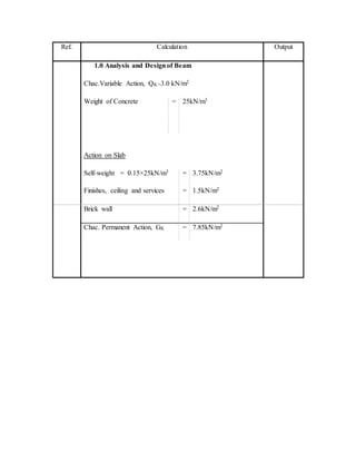
  • 1. Ref. Calculation Output 1.0 Analysis and Designof Beam Chac.Variable Action, QK =3.0 kN/m2 Weight of Concrete = 25kN/m3 Action on Slab Self-weight = 0.15×25kN/m3 = 3.75kN/m2 Finishes, ceiling and services = 1.5kN/m2 Brick wall = 2.6kN/m2 Chac. Permanent Action, GK = 7.85kN/m2
  • 2. Ref. Calculation Output Distribution of Actions from Slabs Slab1 : 𝐼 𝑦 𝐼𝑥 = 4.675𝑚 2.699𝑚 = 1.732 ˂ 2.0 Slab 2 : 𝐼 𝑦 𝐼𝑥 = 3.802𝑚 3.475𝑚 = 1.094˂ 2.0 Slab 3 : 𝐼 𝑦 𝐼𝑥 = 5.698𝑚 2.939𝑚 = 1.94˂ 2.0 Action from Slab Slab1 w1GK1 = 0.26×7.85kN/m2×0.803m = 1.639kN/m w1QK1 = 0.26×3.0kN/m2×0.803m = 0.626kN/m w2GK2 = 0.40×7.85kN/m2×1.896m = 5.953kN/m w2QK2 = 0.40 ×3.0kN/m2×1.896m = 2.275kN/m Slab2 w3GK3 = 0.36×7.85kN/m2×2.939m = 8.306kN/m w3QK3 = 0.36×3.00kN/m2×2.939m = 3.174kN/m Two Way Slab
  • 3. Ref. Calculation Output Action on Beam Beam Self-weight = 0.20m × (0.5-0.15)m × 25 kN/m3 = 1.75kN/m Span A – B Permanent Action, GK = 6.6825kN/m + kN/m + 1.75kN/m = 14.5892kN/m Variable Action, QK = 2.4300kN/m + 1.7843kN/m = 4.2143N/m Span B – C Permanent Action, GK = 6.1256kN/m + 8.4923kN/m + 3.00kN/m = 17.6179kN/m Variable Action, QK = 2.2275kN/m + 3.0881kN/m = 5.3156kN/m
  • 4.
  • 5. Ref. Calculation Output Span C – D Permanent Action, GK = 7.9819kN/m + 6.2370kN/m + 3.00kN/m = 17.2189kN/m Variable Action, QK = 2.9025kN/m + 2.2680kN/m = 5.1705kN/m Span D – E Permanent Action, GK = 4.6963kN/m + 7.4003kN/m + 3.00kN/m = 15.0966kN/m Variable Action, QK = 1.7078kN/m + 2.6910kN/m = 4.3988kN/m Span E – F Permanent Action, GK = 5.9214kN/m + 6.4598kN/m + 3.00kN/m = 15.3812kN/m Variable Action, QK = 2.1533kN/m + 2.3490kN/m = 4.5023kN/m
  • 6. Span F – G Permanent Action, GK = 4.9005kN/m + 5.3460kN/m + 3.00kN/m = 13.2465kN/m Variable Action, QK = 1.782kN/m + 1.9440kN/m = 3.7260kN/m
  • 7. Ref. Calculation Output Span G – H Permanent Action, GK = 8.1675kN/m + 9.9000kN/m + 3.00kN/m = 21.0675kN/m Variable Action, QK = 2.9700kN/m + 3.6000kN/m = 6.5700kN/m
  • 8. Ref. Calculation Output 6.1 Load Distribution of Beam Case 1: Maximum Loading FEM FEMAB = -FEMBA = − 𝑤𝐿2 12 = − [1.35 (14.5892 𝑘𝑁 𝑚⁄ )+1.50(4.2143𝑘𝑁 𝑚⁄ )](2.2875𝑚)2 12 = -11.3448 kNm FEMBC = -FEMCB = − 𝑤𝐿2 12 = − [1.35 (17.6179 𝑘𝑁 𝑚⁄ )+1.50(5.3156𝑘𝑁 𝑚⁄ )](2.2875𝑚)2 12 = -13.8480 kNm FEMCD = -FEMDC = − 𝑤𝐿2 12 = − [1.35 (17.2189 𝑘𝑁 𝑚⁄ )+1.50(5.1705𝑘𝑁 𝑚⁄ )](3.225𝑚)2 12 = -26.8694 kNm FEMDE = -FEMED = − 𝑤𝐿2 12 = − [1.35 (15.0966 𝑘𝑁 𝑚⁄ )+1.50(4.3988 𝑘𝑁 𝑚⁄ )](1.725𝑚)2 12 = -6.6899 kNm FEMEF = -FEMFE = − 𝑤𝐿2 12 = − [1.35 (15.3812 𝑘𝑁 𝑚⁄ )+1.50(4.5023𝑘𝑁 𝑚⁄ )](2.175𝑚)2 12 = -10.8481 kNm FEMFG = -FEMGF = − 𝑤𝐿2 12
  • 9. = − [1.35 (13.2465 𝑘𝑁 𝑚⁄ )+1.50(3.7260𝑘𝑁 𝑚⁄ )](1.8𝑚)2 12 = -6.3374 kNm FEMGH = -FEMHG = − 𝑤𝐿2 12 = − [1.35 (21.0675 𝑘𝑁 𝑚⁄ )+1.50(6.5700𝑘𝑁 𝑚⁄ )](3.0𝑚)2 12 = -28.7221 kNm
  • 10. Moment Distribution Mem AB BA BC CB CD DC DE ED EF FE FG GF GH HG CF 0 0.5 0.5 0.5 0.5 0.5 0.5 0.5 0.5 0.5 0.5 0.5 0.5 0 DF 1 0.5 0.5 0.585 0.415 0.3485 0.6515 0.5577 0.4423 0.4528 0.5472 0.625 0.375 1 FEM -11.3448 11.3448 -13.8480 13.8480 -26.8694 26.8694 -6.6899 6.6899 -10.8481 10.8481 -6.3374 6.3374 -28.7221 28.7221 Dist 11.3448 1.2516 1.2516 7.6175 5.4039 -7.0326 -13.1470 2.3191 1.8392 -2.0425 -2.4683 13.9904 8.3943 -28.7221 Co 0.6258 0 3.8087 0.6258 -3.5163 2.7019 1.1595 -6.5735 -1.0212 0.9196 6.9952 -1.2341 0 4.1971 Dist -0.6258 -1.9044 -1.9044 1.6909 1.1995 -1.3457 -2.5157 4.2356 3.3591 -3.5838 -4.3310 0.7713 0.4628 -4.1971 Co -0.9522 0 0.8455 -0.9522 -0.6729 0.5998 2.1178 -1.2579 -1.7919 1.6796 0.3857 -2.1655 0 0.2314 Dist 0.9522 -0.4227 -0.4227 0.9507 0.6744 -0.9471 -1.7705 1.7009 1.3489 -0.9351 -1.1301 1.3534 0.8121 -0.2314 Co -0.2114 0 0.4753 -0.2114 -0.4735 0.3372 0.8504 -0.8852 -0.4676 0.6745 0.6767 -0.5651 0 0.4060 Dist 0.2114 -0.2377 -0.2377 0.4007 0.2842 -0.4139 -0.7737 0.7545 0.5984 -0.6118 -0.7394 0.3532 0.2119 -0.4060 Co -0.1188 0 0.2003 -0.1188 -0.2069 0.1421 0.3772 -0.3869 -0.3059 0.2992 0.1766 -0.3697 0 0.1059 Dist 0.1188 -0.1002 -0.1002 0.1906 0.1352 -0.1810 -0.3384 0.3864 0.3064 -0.2154 -0.2603 0.2311 0.1386 -0.1059 Co -0.0501 0 0.0953 -0.0501 -0.0905 0.0676 0.1932 -0.1692 -0.1077 0.1532 0.1155 -0.1302 0 0.0693 Dist 0.0501 -0.0476 -0.0476 0.0822 0.0583 -0.0909 -0.1699 0.1544 0.1225 -0.1217 -0.1471 0.0814 0.0488 -0.0693 0 9.8838 -9.8838 24.0739 -24.0739 20.7069 -20.7069 6.9680 -6.9680 7.0638 -7.0638 18.6536 -18.6536 0
  • 11. Ref. Calculation Output Uniform Distribution Loading Loading at Span A – B = [1.35(14.5892kN/m) + 1.50(4.2143kN/m)] = 26.0169kN/m Loading at Span B – C = [1.35(17.6179kN/m) + 1.50(5.3156kN/m)] = 31.7575 kN/m Loading at Span C – D = [1.35(17.2189kN/m) + 1.50(5.1705kN/m)] = 31.0013 kN/m Loading at Span D – E = [1.35(15.0966kN/m) + 1.50(4.3988kN/m)] = 26.9786 kN/m Loading at Span E – F = [1.35(15.3812kN/m) + 1.50(4.5023kN/m)] = 26.9786 kN/m Loading at Span E – F = [1.35(15.3812kN/m) + 1.50(4.5023kN/m)] = 27.5181 kN/m Loading at Span F – G = [1.35(13.2465kN/m) + 1.50(3.7260kN/m)] = 23.4718 kN/m
  • 12. Loading at Span G – H = [1.35(21.0675kN/m) + 1.50(6.5700kN/m)] = 38.2961 kN/m
  • 13. Ref. Calculation Output Span A – B +↻ ∑ 𝑀 𝐵 = 0 = 2.2875𝑚 𝑅 𝐴 − (26.0169 𝑘𝑁 𝑚⁄ )(2.2875𝑚)( 2.2875𝑚 2 ) − 0𝑘𝑁𝑚 + 9.8838𝑘𝑁𝑚 RA = 25.436kN ↑ ∑ 𝐹𝑦 = ↓ ∑ 𝐹𝑦 RA - RB1 = 26.0169kN/m (2.2875m) RB1 = 34.078kN → ∑ 𝐻𝐴 = ← ∑ 𝐻 𝐵1 = 0
  • 14. Ref. Calculation Output Span B – C +↻ ∑ 𝑀 𝐶 = 0 = 2.2875𝑚𝑅 𝐵2 − (31.7575 𝑘𝑁 𝑚⁄ )(2.2875𝑚)( 2.2875𝑚 2 ) − 9.8838𝑘𝑁𝑚 + 24.0739𝑘𝑁𝑚 RB2 = 30.119kN ↑ ∑ 𝐹𝑦 = ↓ ∑ 𝐹𝑦 RB2 + RC1 = 31.7575 kN/m (2.2875m) RC1 = 42.526kN → ∑ 𝐻 𝐵2 = ← ∑ 𝐻 𝐶1 = 0
  • 15. Ref. Calculation Output Span C – D +↻ ∑ 𝑀 𝐷 = 0 = 3.225𝑚𝑅 𝐶2 − (31.0013 𝑘𝑁 𝑚⁄ )(3.225𝑚)( 3.225𝑚 2 ) − 24.0739𝑘𝑁𝑚 + 20.7069𝑘𝑁𝑚 RC2 = 51.034kN ↑ ∑ 𝐹𝑦 = ↓ ∑ 𝐹𝑦 RC2 + RD1 = 31.0013kN/m (3.225m) RD1 = 48.945kN → ∑ 𝐻 𝐶2 = ← ∑ 𝐻 𝐷1 = 0
  • 16. Ref. Calculation Output Span D - E +↻ ∑ 𝑀 𝐸 = 0 = 1.725𝑚𝑅 𝐷2 − (26.9786 𝑘𝑁 𝑚⁄ )(1.725𝑚)( 1.725𝑚 2 ) − 20.7069𝑘𝑁𝑚 + 6.9680𝑘𝑁𝑚 RD2 = 31.234kN ↑ ∑ 𝐹𝑦 = ↓ ∑ 𝐹𝑦 RD2 + RE1 = 26.9786 kN/m (1.725m) RE1 = 15.304kN → ∑ 𝐻 𝐷2 = ← ∑ 𝐻 𝐸1 = 0
  • 17. Ref. Calculation Output Span E – F +↻ ∑ 𝑀 𝐸 = 0 = 2.175𝑚𝑅 𝐸2 − (27.5181 𝑘𝑁 𝑚⁄ )(2.175𝑚)( 2.175𝑚 2 ) − 6.9680𝑘𝑁𝑚 + 7.0638𝑘𝑁𝑚 RE2 = 29.882kN ↑ ∑ 𝐹𝑦 = ↓ ∑ 𝐹𝑦 RE2 + RF1 = 27.5181kN/m (2.175m) RF1 = 29.970kN → ∑ 𝐻 𝐸2 = ← ∑ 𝐻 𝐹1 = 0
  • 18. Ref. Calculation Output Span F – G +↻ ∑ 𝑀 𝐹 = 0 = 1.8𝑚𝑅 𝐹2 − (23.4718𝑘𝑁 𝑚⁄ )(1.8𝑚)( 1.8𝑚 2 ) − 7.0638𝑘𝑁𝑚 + 18.6536𝑘𝑁𝑚 RF2 = 14.686kN ↑ ∑ 𝐹𝑦 = ↓ ∑ 𝐹𝑦 RF2 + RG1 = 23.4718kN/m (1.8m) RG1 = 27.563kN → ∑ 𝐻 𝐹2 = ← ∑ 𝐻 𝐺1 = 0
  • 19. Ref. Calculation Output Span G – H +↻ ∑ 𝑀 𝐺 = 0 = 3.0𝑚𝑅 𝐺2 − (38.2961 𝑘𝑁 𝑚⁄ )(3.0𝑚)( 3.0𝑚 2 ) − 18.6536𝑘𝑁𝑚 + 0𝑘𝑁𝑚 RG2 = 63.662kN ↑ ∑ 𝐹𝑦 = ↓ ∑ 𝐹𝑦 RG2 + RH = 38.2961kN/m (3.0m) RH = 1.226kN → ∑ 𝐻 𝐺2 = ← ∑ 𝐻 𝐻 = 0
  • 20. Ref. Calculation Output Summary At point A,𝑅 𝐴 = 25.436𝑘𝑁 ↺ 𝑀𝐴 = 0𝑘𝑁𝑚 At point B,𝑅 𝐵 = 64.197𝑘𝑁 ↺ 𝑀 𝐵 = −9.884𝑘𝑁𝑚 ↻ 𝑀 𝐵 = +9.884𝑘𝑁𝑚 At point C,𝑅 𝐶 = 93.560𝑘𝑁 ↺ 𝑀𝑐 = −24.074𝑘𝑁𝑚 ↻ 𝑀𝑐 = +24.074𝑘𝑁𝑚 At point D,𝑅 𝐷 = 80.179𝑘𝑁 ↺ 𝑀 𝐷 = −20.707𝑘𝑁𝑚 ↻ 𝑀 𝐷 = +20.707𝑘𝑁𝑚 At point E,𝑅 𝐸 = 45.186𝑘𝑁 ↺ 𝑀 𝐸 = −6.968𝑁𝑚 ↻ 𝑀 𝐸 = +6.968𝑁𝑚 At point F,𝑅 𝐹 = 44.656𝑘𝑁
  • 21. ↺ 𝑀 𝐹 = −7.064𝑘𝑁𝑚 ↻ 𝑀 𝐹 = +7.064𝑘𝑁𝑚 At point G,𝑅 𝐺 = 91.225𝑘𝑁 ↺ 𝑀 𝐺 = −18.654𝑘𝑁𝑚 ↻ 𝑀 𝐺 = +18.654𝑘𝑁𝑚 At point H,𝑅 𝐻 = 51.226𝑘𝑁 ↻ 𝑀 𝐻 = 0𝑘𝑁𝑚 Ref. Calculation Output 6.2 Load Distribution of Beam Case 2: Alternative Loading FEM FEMAB = -FEMBA = − 𝑤𝐿2 12 = − [1.35 (14.5892 𝑘𝑁 𝑚⁄ )+1.50(4.2143𝑘𝑁 𝑚⁄ )](2.2875𝑚)2 12 = -11.3448 kNm FEMBC = -FEMCB = − 𝑤𝐿2 12 = − [1.35 (17.6179 𝑘𝑁 𝑚⁄ )](2.2875𝑚)2 12 = -10.3712 kNm
  • 22. FEMCD = -FEMDC = − 𝑤𝐿2 12 = − [1.35 (17.2189 𝑘𝑁 𝑚⁄ )+1.50(5.1705𝑘𝑁 𝑚⁄ )](3.225𝑚)2 12 = -26.8694 kNm FEMDE = -FEMED = − 𝑤𝐿2 12 = =− [1.35(15.0966 𝑘𝑁 𝑚⁄ )](1.725𝑚)2 12 = -5.0537 kNm FEMEF = -FEMFE = − 𝑤𝐿2 12 = − [1.35 (15.3812 𝑘𝑁 𝑚⁄ )+1.50(4.5023𝑘𝑁 𝑚⁄ )](2.175𝑚)2 12 = -10.8481 kNm FEMFG = -FEMGF = − 𝑤𝐿2 12 = − [1.35 (13.2465 𝑘𝑁 𝑚⁄ )](1.8𝑚)2 12 = -4.8283 kNm FEMGH = -FEMHG = − 𝑤𝐿2 12 = − [1.35 (21.0675 𝑘𝑁 𝑚⁄ )+1.50(6.5700𝑘𝑁 𝑚⁄ )](3.0𝑚)2 12 = -28.7221 kNm
  • 23. Moment Distribution Mem AB BA BC CB CD DC DE ED EF FE FG GF GH HG CF 0.000 0.500 0.500 0.500 0.500 0.500 0.500 0.500 0.500 0.500 0.500 0.500 0.500 0.000 DF 1.000 0.500 0.500 0.585 0.415 0.349 0.652 0.558 0.442 0.453 0.547 0.625 0.375 1.000 FEM -11.3448 11.3448 -10.3712 10.3712 -26.8694 26.8694 -5.0537 5.0537 -10.8481 10.8481 -4.8283 4.8283 -28.7221 28.7221 Dist 11.3448 -0.4868 -0.4868 9.6514 6.8467 -7.6028 -14.2129 3.2316 2.5629 -2.7258 -3.2940 14.9336 8.9602 -28.7221 Co -0.2434 0.0000 4.8257 -0.2434 -3.8014 3.4234 1.6158 -7.1065 -1.3629 1.2814 7.4668 -1.6470 0.0000 4.4801 Dist 0.2434 -2.4129 -2.4129 2.3662 1.6786 -1.7561 -3.2830 4.7233 3.7460 -3.9612 -4.7870 1.0294 0.6176 -4.4801 Co -1.2064 0.0000 1.1831 -1.2064 -0.8781 0.8393 2.3617 -1.6415 -1.9806 1.8730 0.5147 -2.3935 0.0000 0.3088 Dist 1.2064 -0.5915 -0.5915 1.2194 0.8651 -1.1155 -2.0854 2.0200 1.6021 -1.0811 -1.3065 1.4959 0.8976 -0.3088 Co -0.2958 0.0000 0.6097 -0.2958 -0.5578 0.4325 1.0100 -1.0427 -0.5406 0.8010 0.7480 -0.6533 0.0000 0.4488 Dist 0.2958 -0.3049 -0.3049 0.4993 0.3542 -0.5027 -0.9398 0.8830 0.7003 -0.7014 -0.8476 0.4083 0.2450 -0.4488 Co -0.1524 0.0000 0.2497 -0.1524 -0.2514 0.1771 0.4415 -0.4699 -0.3507 0.3501 0.2041 -0.4238 0.0000 0.1225 Dist 0.1524 -0.1248 -0.1248 0.2362 0.1676 -0.2156 -0.4030 0.4577 0.3630 -0.2510 -0.3033 0.2649 0.1589 -0.1225 Co -0.0624 0.0000 0.1181 -0.0624 -0.1078 0.0838 0.2288 -0.2015 -0.1255 0.1815 0.1324 -0.1517 0.0000 0.0795 Dist 0.0624 -0.0591 -0.0591 0.0996 0.0706 -0.1089 -0.2037 0.1824 0.1446 -0.1421 -0.1718 0.0948 0.0569 -0.0795 0.0000 7.3648 -7.3648 22.4829 -22.4829 20.5238 -20.5238 6.0896 -6.0896 6.4726 -6.4726 17.7860 -17.7860 0.0000
  • 24. Ref. Calculation Output Uniform Distribution Loading Loading at Span A – B = [1.35(14.5892kN/m) + 1.50(4.2143kN/m)] = 26.0169kN/m Loading at Span B – C = [1.35(17.6179kN/m)] = 23.7842kN/m Loading at Span C – D = [1.35(17.2189kN/m) + 1.50(5.1705kN/m)] = 31.0013 kN/m Loading at Span D – E = [1.35(15.0966kN/m)] = 20.3804kN/m Loading at Span E – F = [1.35(15.3812kN/m) + 1.50(4.5023kN/m)] = 26.9786 kN/m Loading at Span E – F = [1.35(15.3812kN/m) + 1.50(4.5023kN/m)] = 27.5181 kN/m Loading at Span F – G = [1.35(13.2465kN/m)] = 17.8828kN/m
  • 25. Loading at Span G – H = [1.35(21.0675kN/m) + 1.50(6.5700kN/m)] = 38.2961 kN/m
  • 26. Ref. Calculation Output Span A – B +↻ ∑ 𝑀 𝐵 = 0 = 2.2875𝑚 𝑅 𝐴 − (26.0169 𝑘𝑁 𝑚⁄ )(2.2875𝑚)( 2.2875𝑚 2 ) + 7.3648𝑘𝑁𝑚 RA = 26.537kN ↑ ∑ 𝐹𝑦 = ↓ ∑ 𝐹𝑦 RA - RB1 = 26.0169kN/m (2.2875m) RB1 = 32.976kN → ∑ 𝐻𝐴 = ← ∑ 𝐻 𝐵1 = 0
  • 27. Ref. Calculation Output Span B – C +↻ ∑ 𝑀 𝐶 = 0 = 2.2875𝑚𝑅 𝐵2 − (23.7842𝑘𝑁 𝑚⁄ )(2.2875𝑚)( 2.2875𝑚 2 ) − 7.3648𝑘𝑁𝑚 + 22.4829𝑘𝑁𝑚 RB2 = 20.594kN ↑ ∑ 𝐹𝑦 = ↓ ∑ 𝐹𝑦 RB2 + RC1 = 23.7842kN/m (2.2875m) RC1 = 33.812kN → ∑ 𝐻 𝐵2 = ← ∑ 𝐻 𝐶1 = 0
  • 28. Ref. Calculation Output Span C – D +↻ ∑ 𝑀 𝐷 = 0 = 3.225𝑚𝑅 𝐶2 − (31.0013 𝑘𝑁 𝑚⁄ )(3.225𝑚)( 3.225𝑚 2 ) − 22.4829𝑘𝑁𝑚 + 20.5238𝑘𝑁𝑚 RC2 = 50.597kN ↑ ∑ 𝐹𝑦 = ↓ ∑ 𝐹𝑦 RC2 + RD1 = 31.0013kN/m (3.225m) RD1 = 49.382kN → ∑ 𝐻 𝐶2 = ← ∑ 𝐻 𝐷1 = 0
  • 29. Ref. Calculation Output Span D - E +↻ ∑ 𝑀 𝐸 = 0 = 1.725𝑚𝑅 𝐷2 − (20.3804 𝑘𝑁 𝑚⁄ )(1.725𝑚)( 1.725𝑚 2 ) − 20.5238𝑘𝑁𝑚 + 6.0896𝑘𝑁𝑚 RD2 = 25.946kN ↑ ∑ 𝐹𝑦 = ↓ ∑ 𝐹𝑦 RD2 + RE1 = 20.3804kN/m (1.725m) RE1 = 9.210kN → ∑ 𝐻 𝐷2 = ← ∑ 𝐻 𝐸1 = 0
  • 30. Ref. Calculation Output Span E – F +↻ ∑ 𝑀 𝐸 = 0 = 2.175𝑚𝑅 𝐸2 − (27.5181 𝑘𝑁 𝑚⁄ )(2.175𝑚)( 2.175𝑚 2 ) − 6.0896𝑘𝑁𝑚 + 6.4726𝑘𝑁𝑚 RE2 = 9.750kN ↑ ∑ 𝐹𝑦 = ↓ ∑ 𝐹𝑦 RE2 + RF1 = 27.5181kN/m (2.175m) RF1 = 30.102kN → ∑ 𝐻 𝐸2 = ← ∑ 𝐻 𝐹1 = 0
  • 31. Ref. Calculation Output Span F – G +↻ ∑ 𝑀 𝐹 = 0 = 1.8𝑚𝑅 𝐹2 − (17.8828𝑘𝑁 𝑚⁄ )(1.8𝑚)( 1.8𝑚 2 ) − 6.4726𝑘𝑁𝑚 + 17.7860𝑘𝑁𝑚 RF2 = 9.809kN ↑ ∑ 𝐹𝑦 = ↓ ∑ 𝐹𝑦 RF2 + RG1 = 17.8828kN/m (1.8m) RG1 = 22.380kN → ∑ 𝐻 𝐹2 = ← ∑ 𝐻 𝐺1 = 0
  • 32. Ref. Calculation Output Span G – H +↻ ∑ 𝑀 𝐺 = 0 = 3.0𝑚𝑅 𝐺2 − (38.2961 𝑘𝑁 𝑚⁄ )(3.0𝑚)( 3.0𝑚 2 ) − 17.7860𝑘𝑁𝑚 RG2 = 63.373kN ↑ ∑ 𝐹𝑦 = ↓ ∑ 𝐹𝑦 RG2 + RH = 38.2961kN/m (3.0m) RH = 51.516kN → ∑ 𝐻 𝐺2 = ← ∑ 𝐻 𝐻 = 0
  • 33. Ref. Calculation Output Summary At point A,𝑅 𝐴 = 26.537𝑘𝑁 ↺ 𝑀𝐴 = 0𝑘𝑁𝑚 At point B,𝑅 𝐵 = 53.571𝑘𝑁 ↺ 𝑀 𝐵 = −7.365𝑘𝑁𝑚 ↻ 𝑀 𝐵 = +7.365𝑘𝑁𝑚 At point C,𝑅 𝐶 = 84.409𝑘𝑁 ↺ 𝑀𝑐 = −22.483𝑘𝑁𝑚 ↻ 𝑀𝑐 = +22.483𝑘𝑁𝑚 At point D,𝑅 𝐷 = 75.328𝑘𝑁 ↺ 𝑀 𝐷 = −20.524𝑘𝑁𝑚 ↻ 𝑀 𝐷 = +20.524𝑘𝑁𝑚 At point E,𝑅 𝐸 = 38.960𝑘𝑁 ↺ 𝑀 𝐸 = −6.090𝑘𝑁𝑚 ↻ 𝑀 𝐸 = +6.090𝑁𝑚 At point F,𝑅 𝐹 = 39.911𝑘𝑁
  • 34. ↺ 𝑀 𝐹 = −6.473𝑘𝑁𝑚 ↻ 𝑀 𝐹 = +6.473𝑘𝑁𝑚 At point G,𝑅 𝐺 = 85.753𝑘𝑁 ↺ 𝑀 𝐺 = −17.786𝑘𝑁𝑚 ↻ 𝑀 𝐺 = +17.786𝑘𝑁𝑚 At point H,𝑅 𝐻 = 51.516𝑘𝑁 ↻ 𝑀 𝐻 = 0𝑘𝑁𝑚 Ref. Calculation Output 6.3 Load Distribution of Beam Case 3: Adjacent Loading FEM FEMAB = -FEMBA = − 𝑤𝐿2 12 = − [1.35 (14.5892 𝑘𝑁 𝑚⁄ )](2.2875𝑚)2 12 = -8.5883 kNm FEMBC = -FEMCB = − 𝑤𝐿2 12 = − [1.35 (17.6179 𝑘𝑁 𝑚⁄ )+1.50(5.3156𝑘𝑁 𝑚⁄ )](2.2875𝑚)2 12 = -13.8480 kNm
  • 35. FEMCD = -FEMDC = − 𝑤𝐿2 12 = − [1.35 (17.2189 𝑘𝑁 𝑚⁄ )+1.50(5.1705𝑘𝑁 𝑚⁄ )](3.225𝑚)2 12 = -26.8694 kNm FEMDE = -FEMED = − 𝑤𝐿2 12 = =− [1.35(15.0966 𝑘𝑁 𝑚⁄ )](1.725𝑚)2 12 = -5.0537 kNm FEMEF = -FEMFE = − 𝑤𝐿2 12 = − [1.35 (15.3812 𝑘𝑁 𝑚⁄ )+1.50(4.5023𝑘𝑁 𝑚⁄ )](2.175𝑚)2 12 = -10.8481 kNm FEMFG = -FEMGF = − 𝑤𝐿2 12 = − [1.35 (13.2465 𝑘𝑁 𝑚⁄ )+1.50(3.7260𝑘𝑁 𝑚⁄ )](1.8𝑚)2 12 = -6.3374 kNm FEMGH = -FEMHG = − 𝑤𝐿2 12 = − [1.35 (21.0675 𝑘𝑁 𝑚⁄ )](3.0𝑚)2 12 = -21.3308 kNm
  • 36. Moment Distribution Mem AB BA BC CB CD DC DE ED EF FE FG GF GH HG CF 0 0.5 0.5 0.5 0.5 0.5 0.5 0.5 0.5 0.5 0.5 0.5 0.5 0 DF 1 0.5 0.5 0.585 0.415 0.3485 0.6515 0.5577 0.4423 0.4528 0.5472 0.625 0.375 1 FEM -8.5883 8.5883 -13.8480 13.8480 -26.8694 26.8694 -5.0537 5.0537 -10.8481 10.8481 -6.3374 6.3374 -21.3308 21.3308 Dist 8.5883 2.6299 2.6299 7.6175 5.4039 -7.6028 -14.2129 3.2316 2.5629 -2.0425 -2.4683 9.3709 5.6225 -21.3308 Co 1.3149 0.0000 3.8087 1.3149 -3.8014 2.7019 1.6158 -7.1065 -1.0212 1.2814 4.6855 -1.2341 0.0000 2.8113 Dist -1.3149 -1.9044 -1.9044 1.4546 1.0319 -1.5047 -2.8130 4.5328 3.5949 -2.7018 -3.2651 0.7713 0.4628 -2.8113 Co -0.9522 0.0000 0.7273 -0.9522 -0.7524 0.5159 2.2664 -1.4065 -1.3509 1.7974 0.3857 -1.6325 0.0000 0.2314 Dist 0.9522 -0.3636 -0.3636 0.9972 0.7074 -0.9696 -1.8127 1.5378 1.2196 -0.9885 -1.1946 1.0203 0.6122 -0.2314 Co -0.1818 0.0000 0.4986 -0.1818 -0.4848 0.3537 0.7689 -0.9063 -0.4943 0.6098 0.5102 -0.5973 0.0000 0.3061 Dist 0.1818 -0.2493 -0.2493 0.3900 0.2767 -0.3912 -0.7314 0.7811 0.6195 -0.5071 -0.6128 0.3733 0.2240 -0.3061 Co -0.1246 0.0000 0.1950 -0.1246 -0.1956 0.1383 0.3906 -0.3657 -0.2536 0.3097 0.1867 -0.3064 0.0000 0.1120 Dist 0.1246 -0.0975 -0.0975 0.1874 0.1329 -0.1843 -0.3446 0.3454 0.2739 -0.2248 -0.2716 0.1915 0.1149 -0.1120 Co -0.0487 0.0000 0.0937 -0.0487 -0.0922 0.0665 0.1727 -0.1723 -0.1124 0.1369 0.0958 -0.1358 0.0000 0.0575 Dist 0.0487 -0.0468 -0.0468 0.0824 0.0585 -0.0833 -0.1558 0.1588 0.1259 -0.1054 -0.1273 0.0849 0.0509 -0.0575 0.0000 8.5565 -8.5565 24.5846 -24.5846 19.9097 -19.9097 5.6838 -5.6838 8.4135 -8.4135 14.2435 -14.2435 0.0000
  • 37. 37 Ref. Calculation Output Uniform Distribution Loading Loading at Span A – B = [1.35(14.5892kN/m)] = 19.6954kN/m Loading at Span B – C = [1.35(17.6179kN/m) + 1.50(5.3156kN/m)] = 31.7576kN/m Loading at Span C – D = [1.35(17.2189kN/m) + 1.50(5.1705kN/m)] = 31.0013 kN/m Loading at Span D – E = [1.35(15.0966kN/m)] = 20.3804kN/m Loading at Span E – F = [1.35(15.3812kN/m) + 1.50(4.5023kN/m)] = 27.5181kN/m Loading at Span E – F = [1.35(15.3812kN/m) + 1.50(4.5023kN/m)] = 27.5181 kN/m Loading at Span F – G = [1.35(13.2465kN/m) + 1.50(3.7260kN/m)] = 23.4718kN/m
  • 38. 38 Loading at Span G – H = [1.35(21.0675kN/m)] = 28.4411kN/m
  • 39. 39 Ref. Calculation Output Span A – B +↻ ∑ 𝑀 𝐵 = 0 = 2.2875𝑚 𝑅 𝐴 − (19.6954 𝑘𝑁 𝑚⁄ )(2.2875𝑚)( 2.2875𝑚 2 ) − 0𝑘𝑁𝑚 + 8.5565𝑘𝑁𝑚 RA = 18.786kNm ↑ ∑ 𝐹𝑦 = ↓ ∑ 𝐹𝑦 RA - RB1 = 19.6954kN/m (2.2875m) RB1 = 26.267kN → ∑ 𝐻𝐴 = ← ∑ 𝐻 𝐵1 = 0
  • 40. 40 Ref. Calculation Output Span B – C +↻ ∑ 𝑀 𝐶 = 0 = 2.2875𝑚𝑅 𝐵2 − (31.7576𝑘𝑁 𝑚⁄ )(2.2875𝑚)( 2.2875𝑚 2 ) − 8.5565𝑘𝑁𝑚 + 24.5846𝑘𝑁𝑚 RB2 = 29.316kN ↑ ∑ 𝐹𝑦 = ↓ ∑ 𝐹𝑦 RB2 + RC1 = 31.7576kN/m (2.2875m) RC1 = 43.330kN → ∑ 𝐻 𝐵2 = ← ∑ 𝐻 𝐶1 = 0
  • 41. 41 Ref. Calculation Output Span C – D +↻ ∑ 𝑀 𝐷 = 0 = 3.225𝑚𝑅 𝐶2 − (31.0013 𝑘𝑁 𝑚⁄ )(3.225𝑚)( 3.225𝑚 2 ) − 24.5846𝑘𝑁𝑚 + 19.9097𝑘𝑁𝑚 RC2 = 51.439kN ↑ ∑ 𝐹𝑦 = ↓ ∑ 𝐹𝑦 RC2 + RD1 = 31.0013kN/m (3.225m) RD1 = 48.540kN → ∑ 𝐻 𝐶2 = ← ∑ 𝐻 𝐷1 = 0
  • 42. 42 Ref. Calculation Output Span D - E +↻ ∑ 𝑀 𝐸 = 0 = 1.725𝑚𝑅 𝐷2 − (20.3804 𝑘𝑁 𝑚⁄ )(1.725𝑚)( 1.725𝑚 2 ) − 19.9097𝑘𝑁𝑚 + 5.6838𝑘𝑁𝑚 RD2 = 25.825kN ↑ ∑ 𝐹𝑦 = ↓ ∑ 𝐹𝑦 RD2 + RE1 = 20.3804kN/m (1.725m) RE1 = 9.331kN → ∑ 𝐻 𝐷2 = ← ∑ 𝐻 𝐸1 = 0
  • 43. 43 Ref. Calculation Output Span E – F +↻ ∑ 𝑀 𝐸 = 0 = 2.175𝑚𝑅 𝐸2 − (27.5181 𝑘𝑁 𝑚⁄ )(2.175𝑚)( 2.175𝑚 2 ) − 5.6838𝑘𝑁𝑚 + 8.4135𝑘𝑁𝑚 RE2 = 28.671kN ↑ ∑ 𝐹𝑦 = ↓ ∑ 𝐹𝑦 RE2 + RF1 = 27.5181kN/m (2.175m) RF1 = 31.181kN → ∑ 𝐻 𝐸2 = ← ∑ 𝐻 𝐹1 = 0
  • 44. 44 Ref. Calculation Output Span F – G +↻ ∑ 𝑀 𝐹 = 0 = 1.8𝑚𝑅 𝐹2 − (23.4718𝑘𝑁 𝑚⁄ )(1.8𝑚)( 1.8𝑚 2 ) − 8.4135𝑘𝑁𝑚 + 14.2435𝑘𝑁𝑚 RF2 = 17.886kN ↑ ∑ 𝐹𝑦 = ↓ ∑ 𝐹𝑦 RF2 + RG1 = 23.4718kN/m (1.8m) RG1 = 24.363kN → ∑ 𝐻 𝐹2 = ← ∑ 𝐻 𝐺1 = 0
  • 45. 45 Ref. Calculation Output Span G – H +↻ ∑ 𝑀 𝐺 = 0 = 3.0𝑚𝑅 𝐺2 − (28.4411 𝑘𝑁 𝑚⁄ )(3.0𝑚)( 3.0𝑚 2 ) − 14.2435𝑘𝑁𝑚 + 0𝑘𝑁𝑚 RG2 = 47.410kN ↑ ∑ 𝐹𝑦 = ↓ ∑ 𝐹𝑦 RG2 + RH = 28.4411kN/m (3.0m) RH = 37.914kN → ∑ 𝐻 𝐺2 = ← ∑ 𝐻 𝐻 = 0
  • 46. 46 Ref. Calculation Output Summary At point A,𝑅 𝐴 = 18.786𝑘𝑁 ↺ 𝑀𝐴 = 0𝑘𝑁𝑚 At point B,𝑅 𝐵 = 55.583𝑘𝑁 ↺ 𝑀 𝐵 = −8.557𝑘𝑁𝑚 ↻ 𝑀 𝐵 = +8.557𝑘𝑁𝑚 At point C,𝑅 𝐶 = 94.769𝑘𝑁 ↺ 𝑀𝑐 = −24.585𝑘𝑁𝑚 ↻ 𝑀𝑐 = +24.585𝑘𝑁𝑚 At point D,𝑅 𝐷 = 74.365𝑘𝑁 ↺ 𝑀 𝐷 = −19.910𝑘𝑁𝑚 ↻ 𝑀 𝐷 = +19.910𝑘𝑁𝑚 At point E,𝑅 𝐸 = 38.002𝑘𝑁 ↺ 𝑀 𝐸 = −5.684𝑘𝑁𝑚 ↻ 𝑀 𝐸 = +5.684𝑘𝑁𝑚 At point F,𝑅 𝐹 = 49.067𝑘𝑁 ↺ 𝑀 𝐹 = −8.413𝑘𝑁𝑚
  • 47. 47 ↻ 𝑀 𝐹 = +8.413𝑘𝑁𝑚 At point G,𝑅 𝐺 = 71.773𝑘𝑁 ↺ 𝑀 𝐺 = −14.243𝑘𝑁𝑚 ↻ 𝑀 𝐺 = +14.243𝑘𝑁𝑚 At point H,𝑅 𝐻 = 37.914𝑘𝑁 ↻ 𝑀 𝐻 = 0𝑘𝑁𝑚
  • 48. 48 Ref. Calculation Output Distribution Factor, DF KAB = KBA = 4𝐸𝐼 𝐿 = 4𝐸𝐼 2.2875 = 1.7486 EI KBC = KCB = 4𝐸𝐼 𝐿 = 4𝐸𝐼 2.2875 = 1.7486 EI KCD = KDC = 4𝐸𝐼 𝐿 = 4𝐸𝐼 3.225 = 1.2403 EI KDE = KDE = 4𝐸𝐼 𝐿 = 4𝐸𝐼 1.725 = 2.3188 EI KEF = KF = 4𝐸𝐼 𝐿
  • 49. 49 = 4𝐸𝐼 2.175 = 1.8391 EI KFG = KGF = 4𝐸𝐼 𝐿 = 4𝐸𝐼 1.8 = 2.2222 EI KGH = KHG = 4𝐸𝐼 𝐿 = 4𝐸𝐼 3.0 = 1.3333 EI Ref. Calculation Output DFAB = 𝐾 𝐴𝐵 𝐾 𝐴𝐵 +0 = 1.7468 𝐸𝐼 1.7468 𝐸𝐼+0 = 1 DFBA = 𝐾 𝐵𝐴 𝐾 𝐵𝐴 + 𝐾 𝐵𝐶 = 1.7468𝐸𝐼 1.7468 𝐸𝐼+1.7468 𝐸𝐼 = 0.5 DFBC = 𝐾 𝐵𝐶 𝐾 𝐵𝐴 + 𝐾 𝐵𝐶 = 1.7468 𝐸𝐼 1.7468 𝐸𝐼+1.7468 𝐸𝐼 = 0.5 DFCB = 𝐾 𝐶𝐵 𝐾 𝐶𝐵 + 𝐾 𝐶𝐷 = 1.7468 𝐸𝐼 1.7468 𝐸𝐼+1.2403 𝐸𝐼 = 0.585 DFCD = 𝐾 𝐶𝐷 𝐾 𝐶𝐵 +𝐾 𝐶𝐷 = 1.2403 𝐸𝐼 1.7468 𝐸𝐼+1.2403 𝐸𝐼 = 0.415 DFDC = 𝐾 𝐷𝐶 𝐾 𝐷𝐶+ 𝐾 𝐷𝐸 = 1.2403 𝐸𝐼 1.2403 𝐸𝐼+2.3188 𝐸𝐼 = 0.348 5 DFDE = 𝐾 𝐷𝐸 𝐾 𝐷𝐶+ 𝐾 𝐷𝐸 = 2.3188 𝐸𝐼 1.2403 𝐸𝐼+2.3188 𝐸𝐼 = 0.651 5 DFED = 𝐾 𝐸𝐷 𝐾 𝐸𝐷 + 𝐾 𝐸𝐹 = 2.3188 𝐸𝐼 2.3188 𝐸𝐼+1.8391 𝐸𝐼 = 0.557 7 DFEF = 𝐾 𝐸𝐹 𝐾 𝐸𝐷 + 𝐾 𝐸𝐹 = 1.8391 𝐸𝐼 2.3188 𝐸𝐼+1.8391 𝐸𝐼 = 0.442 3 DFFE = 𝐾 𝐹𝐸 𝐾 𝐹𝐸+ 𝐾 𝐹𝐺 = 1.8391 𝐸𝐼 1.8391 𝐸𝐼+2.2222 𝐸𝐼 = 0.452 8 DFFG = 𝐾 𝐹𝐺 𝐾 𝐹𝐸+ 𝐾 𝐹𝐺 = 2.2222 𝐸𝐼 1.8391 𝐸𝐼+2.2222 𝐸𝐼 = 0.547 2
  • 50. 50 DFGF = 𝐾 𝐺𝐹 𝐾 𝐺𝐹 + 𝐾 𝐺𝐻 = 2.2222 𝐸𝐼 2.2222 𝐸𝐼+1.3333 𝐸𝐼 = 0.625 DFGH = 𝐾 𝐺𝐻 𝐾 𝐺𝐹 + 𝐾 𝐺𝐻 = 1.3333 𝐸𝐼 2.2222 𝐸𝐼+1.3333 𝐸𝐼 = 0.375 DFHG = 𝐾 𝐻𝐺 𝐾 𝐻𝐺 + 0 = 1.3333 𝐸𝐼 1.3333 𝐸𝐼+0 = 1
  • 51. 51 Ref. Calculation Output 6.3.1 Simply Supported Beam 1. Specification Effective Span, L = 1.8m Characteristic Action : Finishes, gk = 1.5kN/m Variable, qk = 3.0kN/m Design life = 50 Years Fire Resistance = R90 Exposure Classes = XS3 Materials : Characteristic Strength of Concrete, fck = 30N/mm2 Characteristic Strength of Steel, fyk = 500N/mm2 Characteristic Strength of Link, fyk = 500N/mm2
  • 52. 52 Unit Weight of Reinforced Concrete = 25kN/mm2 Assumed : Øbar = 16mm Ølink = 8mm
  • 53. 53 Ref. Calculation Output 2. Size Overall depth, h = L/13 = 1.8/13 = 0.138462m = 138.462mm Width, b = 0.4h = 0.4(138.4615mm) = 55.385mm Use b x h = 200mm x 350mm 200mm = 70000mm2 350mm
  • 54. 54 Ref. Calculation Output 3. Durability, Fire and Bond Requirements Min. concrete cover regard to bond, Cmin,b = 20mm Min. concrete cover regard to durability, Cmin,dur = 45mm Min. required axis distance for R90 fire resistance, asd = 45mm asd = a + 10 = 55mm Min. concrete cover regard to fire Cmin = 𝑎 𝑠𝑑 − ∅𝑙𝑖𝑛𝑘 − ∅ 𝑏𝑎𝑟 2⁄ = 39mm Allowance in design for deviation, Δ Cdev = 10mm Nominal cover, Cnom = Cmin + Δ Cdev = 49mm Cnom ∴ Cnom = 51mm 51mm 4. Loading and Analysis Loading on Slab 15: Slab Thickness = 0.16m Concrete Unit Weight = 25kN/m3 Self-weight = 25kN/m3 × 0.16m = 4.0kN/m Finishing, ceiling and Services = 1.5kN/m
  • 55. 55 Permanent Action, gk = 5.5kN/m Variable Action, qk = 3.0kN/m FS15 ly = 2.4m lx = 1.8m 𝑙 𝑦 𝑙 𝑥 = 1.33 ˂ 2.0 (2 way slab)
  • 56. 56 Ref. Calculation Output Loading on Slab 16: Slab Thickness = 0.21m Concrete Unit Weight = 25kN/m3 Self-weight = 25kN/m3 × 0.21m = 5.25kN/m Finishing, ceiling and Services = 1.5kN/m Permanent Action, gk = 6.75kN/m Variable Action, qk = 3.0kN/m FS16 ly = 2.4m lx = 1.8m 𝑙 𝑦 𝑙 𝑥 = 1.33 ˂ 2.0 (2 way slab) Load on beam 2-3/D-F
  • 57. 57
  • 58. 58 Ref. Calculation Output Characteristic permanent load, Gk Beam self-weight, βvy = 0.36 and 0.33 Beam self-weight w0 = 0.2m × 0.35m × 25kN/m3 = 1.75 kN/m w15 = βvynlx = 0.36 x 5.5kN/m2 x 1.8m = 3.564kN/m w16 = βvynlx = 0.33 x 6.75kN/m2 x 1.2m = 2.673kN/m = Brickwall w1 = 2.6kN/m2 × 3.0m = 7.8 Total GK = 15.787kN/m Characteristic variable load, Qk w15 = βvynlx = 0.36 x 3.0kN/m2 x 1.8m = 1.944kN/m w16 = βvynlx = 0.33 x 3.0kN/m2 x 1.2m = 1.188kN/m
  • 59. 59 Total QK = 3.132kNm
  • 60. 60 Ref. Calculation Output Design action, Wd = 1.35Gk + 1.5Qk Wd = 1.35(15.787kN/m) + 1.5(3.132kN/m) 26.01 = 26.01 kN/m kN/m Shear Force, V = 𝑊 𝑑 𝐿 2 V = 26.01 𝑘𝑁 𝑚⁄ ×1.8𝑚 2 23.410 = 23.410kN kN Bending Moment, 𝑀 = 𝑊 𝑑 𝐿2 8 M = (26.01𝑘𝑁 𝑚⁄ )(1.8𝑚)2 8 10.534 = 10.534kNm kNm
  • 61. 61 Ref. Calculation Output Effective depth d = h - Cnom - Ølink - Øbar = 350mm-50mm-8mm-16mm d = 278mm 278mm d' = Cnom + Ølink + ∅ 𝑏𝑎𝑟 2 = 36mm Design bending moment, Med = 7.153kNm 𝐾 = 𝑀 𝑏𝑑2 𝑓 𝑐𝑘 = 10 .534 ×106 𝑁𝑚𝑚2 (200𝑚𝑚 )(278𝑚𝑚)2(30𝑁/𝑚𝑚2 ) = 0.0227 Kbal = 0.167 K < Kbal ; Compression reinforcement is not required z = 𝑑[0.5 + √0.25 − 𝐾 𝑏𝑎𝑙 1.134 ] z = 0.82𝑑 z = 227.96mm Area of Tension steel, As 𝐴 𝑠 = 𝐾 𝑏𝑎𝑙 𝑓 𝑐𝑘 𝑏𝑑2 0.87𝑓 𝑦𝑘 𝑧 + 𝐴 𝑠′ = (0.167)(30𝑁 𝑚𝑚2⁄ )(200𝑚𝑚)(278𝑚𝑚 )2 0.87 (500𝑁 𝑚𝑚2⁄ )(226.32𝑚𝑚) + 𝐴 𝑠′ = 780.925mm2
  • 62. 62 Min and max reinforcement area, As,min 𝐴 𝑠,𝑚𝑖𝑛 = 0.26 𝑓𝑐𝑡𝑚 𝑓𝑦𝑘 𝑏𝑑 = 0.26 2.90𝑁 𝑚𝑚2⁄ 500𝑁 𝑚𝑚2⁄ 𝑏𝑑 = 0.001508 bd Exceed 0.0013bd; use 0.0015bd = 83.844mm2 Ref. Calculation Output As,max = 0.04Ac = 0.04 × 200mm × 350mm = 2800mm2 5. Shear Reinforcement Design shear force, Ved = 23.410kN Concrete strut capacity 𝑉𝑅𝑑,𝑚𝑎𝑥 = 0.3𝑏 𝑤 𝑑𝑓𝑐𝑘(1− 𝑓 𝑐𝑘 250 ) (𝑐𝑜𝑡𝜃+𝑡𝑎𝑛𝜃) = 0.3(200𝑚𝑚)(278𝑚𝑚)(30𝑁 𝑚𝑚2⁄ )(1− 30𝑁 𝑚𝑚2⁄ 250 ) (𝑐𝑜𝑡𝜃+𝑡𝑎𝑛𝜃) = 181.962𝑘𝑁 (𝜃 = 22°, 𝑐𝑜𝑡𝜃 = 2.5) = 264.211𝑘𝑁 (𝜃 = 45°, 𝑐𝑜𝑡𝜃 = 1.0) Ved < VRd,maxcot 𝜃= 2.5 Ved < VRd,maxcot 𝜃= 1.0
  • 63. 63 ∴ 𝜽 < 𝟐𝟐° 𝜃 = 0.5 sin−1 [ 𝑉 𝐸𝑑 0.18𝑏 𝑤 𝑑𝑓𝑐𝑘(1− 𝑓 𝑐𝑘 250 ) ] = 0.5 sin−1 [ 18.558×10³ 𝑁 0.18(200𝑚𝑚)(278𝑚𝑚)(30𝑁 𝑚𝑚2⁄ )(1− 30𝑁 𝑚𝑚2⁄ 250 ) ] = 2.01° Use 𝜃 = 22° 𝑡𝑎𝑛𝜃 = 0.40, 𝑐𝑜𝑡𝜃 = 2.5 Shear Link, 𝐴 𝑠𝑤 𝑠 = 𝑉 𝐸𝑑 (0.78𝑓𝑦𝑘 𝑑𝑐𝑜𝑡𝜃) = 23.410×10³ 𝑁 (0.78)(500𝑁 𝑚𝑚2⁄ )(278𝑚𝑚)(2.5) = 0.0864mm Try link: H6 𝐴 𝑠𝑤=28.3mm2 Spacing, s = 28.3 𝑚𝑚2 0.0864 𝑚𝑚 = 327.67mm
  • 64. 64 Ref. Calculation Output Maximum spacing, = 0.75d Smax = 0.75(278mm) = 208.5mm Use: H6 - 200 H6 - 200 Minimum links, 𝐴 𝑠𝑤 𝑠 = 0.08√ 𝑓𝑐𝑘 𝑏 𝑤 𝑓 𝑦𝑘 = 0.08√30 𝑁 𝑚𝑚2⁄ 200𝑚𝑚 500𝑁 𝑚𝑚2⁄ = 0.175 mm Spacing, s = 28.3 𝑚𝑚2 0.175 𝑚𝑚 = 161.454mm < 0.75d Use: H6 - 175 H6 - 175 Minimum Links, 𝐴 𝑠𝑤 𝑠 = 0.08√ 𝑓𝑐𝑘 𝑏 𝑤 𝑓 𝑦𝑘 = 0.08√30 𝑁 𝑚𝑚2⁄ 200𝑚𝑚 500𝑁 𝑚𝑚2⁄ = 0.175mm Spacing, s = 28.3mm2/0.175mm = 161.464mm ˂ 0.75d Use: H6 - 175 Shear resistance of minimum links
  • 65. 65 𝑉 𝑚𝑖𝑛 = 𝐴 𝑠𝑤 𝑠 (0.78𝑓𝑦𝑘 𝑑𝑐𝑜𝑡𝜃) = 28.3𝑚𝑚2 200 𝑚𝑚 (0.78)(500𝑁 𝑚𝑚2⁄ )(278𝑚𝑚)(2.5) = 43.833kN
  • 67. 67 Ref. Calculation Output 6. Deflection Percentage of required tension reinforcement, 𝜌 = 𝐴 𝑠,𝑟𝑒𝑞 𝑏𝑑 = 775.307𝑚𝑚2 (200𝑚𝑚)(278𝑚𝑚) = 0.01405 Reference reinforcement ratio, 𝜌° = √ 𝑓𝑐𝑘 × 10−3 = √30 𝑁 𝑚𝑚2⁄ × 10−3 = 0.00548 Percentage of required compression reinforcement, 𝜌′ = 0 𝜌 > 𝜌° ; Use equation: 𝑙 𝑑 = 𝐾[11 + 1.5√ 𝑓𝑐𝑘 𝜌° 𝜌−𝜌′ + 1 12 √ 𝑓𝑐𝑘√ 𝜌′ 𝜌° 𝑙 𝑑 = 1.0[11+ 1.5√30 𝑁 𝑚𝑚2⁄ 0.00548 0.01405−0 + 1 12 √30 𝑁 𝑚𝑚2⁄ √ 0 0.00548 ] 𝑙 𝑑 = 1.0[11+ 0.5549+ 0] 𝑙 𝑑 = 11.555 Modification factor less than 7m = 1.00 Modification factor for steel area provided, = 𝐴 𝑠,𝑝𝑟𝑜𝑣 𝐴 𝑠,𝑟𝑒𝑞 = 943𝑚𝑚2 780.925𝑚𝑚2
  • 68. 68 = 1.208 <1.5 OK! Allowable span effective depth ratio = (l/d) allowable = 11.555 × 1.208 × 1.00 = 13.954 Actual Span-effective depth, (l/d) actual = 1800 𝑚𝑚 278 𝑚𝑚 = 6.475 < (l/d) allowable OK! Ref. Calculation Output 7. Cracking Limiting crack width, wmax = 0.3mm Steel stress, 𝑓𝑠 = 𝑓𝑦𝑘 1.15 [ 𝐺 𝑘+0.3𝑄 𝑘 1.35𝐺 𝑘+1.5𝑄 𝑘 ] 1 𝛿 = 500 1.15 [ 9.75+0.3(3.0) 1.35(9.75)+1.5(3.0) ]1.0 = 288.813N/mm2 EC2: Max allowable bar spacing = 100mm Table 4.2
  • 69. 69 Bar spacing, S = 200mm- 2(50mm) -2(6mm)-16mm = 72mm < 100mm OK! 8. Detailing
  • 70. 70 Ref. Calculation Output 5.4.2 Continuous Beam 1. Specification Span AB Effective Span, L = 2.2875m Dimension Width = 300mm Depth = 400mm Characteristic Load Permanent Loading, GK = 14.5892kN/m Variable Loading, QK = 4.2143kN/m Design life = 50 Years Fire Resistance = R120 Exposure Cement = XS3 Materials: Unit Weight of Concrete = 25kN/m3 Characteristic strength of concrete, fck = 30N/mm2 Characteristic strength of steel, fyk = 500N/mm2 Characteristic strength of link, fyk = 500Nmm2 Assumed ∅ 𝑏𝑎𝑟 1 = 12mm ∅ 𝑏𝑎𝑟 2 = 8mm
  • 72. 72 Ref. Calculation Output Span BC Effective Span, L = 2.2875m Dimension Width = 300mm Depth = 400mm Characteristic Load Permanent Loading, GK = 17.6179kN/m Variable Loading, QK = 5.3156kN/m Design life = 50 Years Fire Resistance = R120 Exposure Cement = XS3 Materials: Unit Weight of Concrete = 25kN/m3 Characteristic strength of concrete, fck = 30N/mm2 Characteristic strength of steel, fyk = 500N/mm2 Characteristic strength of link, fyk = 500Nmm2 Assumed ∅ 𝑏𝑎𝑟 1 = 12mm ∅ 𝑏𝑎𝑟 2 = 8mm ∅𝑙𝑖𝑛𝑘 = 6mm
  • 73. 73
  • 74. 74 Ref. Calculation Output Span CD Effective Span, L = 3.225m Dimension Width = 300mm Depth = 400mm Characteristic Load Permanent Loading, GK = 17.2189kN/m Variable Loading, QK = 5.1705kN/m Design life = 50 Years Fire Resistance = R120 Exposure Cement = XS3 Materials: Unit Weight of Concrete = 25kN/m3 Characteristic strength of concrete, fck = 30N/mm2 Characteristic strength of steel, fyk = 500N/mm2 Characteristic strength of link, fyk = 500Nmm2 Assumed ∅ 𝑏𝑎𝑟 1 = 12mm ∅ 𝑏𝑎𝑟 2 = 8mm ∅𝑙𝑖𝑛𝑘 = 6mm
  • 75. 75
  • 76. 76 Ref. Calculation Output Span DE Effective Span, L = 1.725m Dimension Width = 300mm Depth = 400mm Characteristic Load Permanent Loading, GK = 15.0966kN/m Variable Loading, QK = 4.3988kN/m Design life = 50 Years Fire Resistance = R120 Exposure Cement = XS3 Materials: Unit Weight of Concrete = 25kN/m3 Characteristic strength of concrete, fck = 30N/mm2 Characteristic strength of steel, fyk = 500N/mm2 Characteristic strength of link, fyk = 500Nmm2 Assumed ∅ 𝑏𝑎𝑟 1 = 12mm ∅ 𝑏𝑎𝑟 2 = 8mm ∅𝑙𝑖𝑛𝑘 = 6mm
  • 77. 77
  • 78. 78 Ref. Calculation Output Span EF Effective Span, L = 2.175m Dimension Width = 300mm Depth = 400mm Characteristic Load Permanent Loading, GK = 15.3812kN/m Variable Loading, QK = 4.5023kN/m Design life = 50 Years Fire Resistance = R120 Exposure Cement = XS3 Materials: Unit Weight of Concrete = 25kN/m3 Characteristic strength of concrete, fck = 30N/mm2 Characteristic strength of steel, fyk = 500N/mm2 Characteristic strength of link, fyk = 500Nmm2 Assumed ∅ 𝑏𝑎𝑟 1 = 12mm ∅ 𝑏𝑎𝑟 2 = 8mm ∅𝑙𝑖𝑛𝑘 = 6mm
  • 79. 79
  • 80. 80 Ref. Calculation Output Span FG Effective Span, L = 1.8m Dimension Width = 300mm Depth = 400mm Characteristic Load Permanent Loading, GK = 13.2465kN/m Variable Loading, QK = 3.7260kN/m Design life = 50 Years Fire Resistance = R120 Exposure Cement = XS3 Materials: Unit Weight of Concrete = 25kN/m3 Characteristic strength of concrete, fck = 30N/mm2 Characteristic strength of steel, fyk = 500N/mm2 Characteristic strength of link, fyk = 500Nmm2 Assumed ∅ 𝑏𝑎𝑟 1 = 12mm ∅ 𝑏𝑎𝑟 2 = 8mm ∅𝑙𝑖𝑛𝑘 = 6mm
  • 81. 81
  • 82. 82 Ref. Calculation Output Span GH Effective Span, L = 3.0m Dimension Width = 300mm Depth = 400mm Characteristic Load Permanent Loading, GK = 21.0675kN/m Variable Loading, QK = 6.570kN/m Design life = 50 Years Fire Resistance = R120 Exposure Cement = XS3 Materials: Unit Weight of Concrete = 25kN/m3 Characteristic strength of concrete, fck = 30N/mm2 Characteristic strength of steel, fyk = 500N/mm2 Characteristic strength of link, fyk = 500Nmm2 Assumed ∅ 𝑏𝑎𝑟 1 = 12mm ∅ 𝑏𝑎𝑟 2 = 8mm ∅𝑙𝑖𝑛𝑘 = 6mm
  • 83. 83
  • 84. 84 Ref. Calculation Output 2. Durability, Fire and Bond Requirement Min. Conc. Cover regard to bond, Cmin,b = 12mm Min. conc. Cover regard to durability, Cmin,dur = 50mm Min. required axis distance for R120 fire resistance asd = 35mm + 10mm = 45mm Min. concrete cover regard to fire, Cmin = 𝑎 𝑠𝑑 − ∅𝑙𝑖𝑛𝑘 − ∅ 𝑏𝑎𝑟 2 = 45mm – 6mm – 0.5(12mm) = 33mm Allowance in design for deviation, ∆Cdev = 10mm Nominal cover Cnom = Cmin + ∆Cdev = 50mm + 10mm = 60mm
  • 85. 85 Ref. Calculation Output 3. Loading and Analysis Span AB Design Load, wd = 1.35GK + 1.50QK = 1.35(14.5892kN/m) + 1.50(4.2143kN/m) = 26.0468kN/m Design Moment Span, MED = (0.09GK + 0.10QK)L2 = [0.09(14.5892𝑘𝑁 𝑚⁄ ) + 0.10(4.2143 𝑘𝑁 𝑚⁄ )](2.2875𝑚)2 = 12.583kNm Support, MED = (0.106GK + 0.106QK)L2 = [0.106(14.5892𝑘𝑁 𝑚⁄ ) + 0.106(4.2143 𝑘𝑁 𝑚⁄ )](2.2875𝑚)2 = 14.4306kNm Shear Force Outer Support, VED = 0.45 × wd × L = 0.45 × 26.0468 𝑘𝑁 𝑚⁄ × 2.2875𝑚 = 26.78kN Inner Support, VED = 0.63 × wd × L = 0.63 × 26.0468 𝑘𝑁 𝑚⁄ × 2.2875𝑚
  • 87. 87 Ref. Calculation Output Span BC Design Load, wd = 1.35GK + 1.50QK = 1.35(17.6179kN/m) + 1.50(5.3156kN/m) = 31.7576kN/m Design Moment Span, MED = (0.09GK + 0.10QK)L2 = [0.09(17.6179𝑘𝑁 𝑚⁄ ) + 0.10(5.3156 𝑘𝑁 𝑚⁄ )](2.2875𝑚)2 = 15.373kNm Support, MED = (0.106GK + 0.106QK)L2 = [0.106(17.6179𝑘𝑁 𝑚⁄ ) + 0.106(5.3156 𝑘𝑁 𝑚⁄ )](2.2875𝑚)2 = 17.6147kNm Shear Force Outer Support, VED = 0.45 × wd × L = 0.45 × 31.7576 𝑘𝑁 𝑚⁄ × 2.2875𝑚 = 32.6904kN Inner Support, VED = 0.63 × wd × L = 0.63 × 31.7576 𝑘𝑁 𝑚⁄ × 2.2875𝑚 = 45.7666kN
  • 88. 88
  • 89. 89 Ref. Calculation Output Span CD Design Load, wd = 1.35GK + 1.50QK = 1.35(17.2189kN/m) + 1.50(5.1705kN/m) = 31.0013kN/m Design Moment Span, MED = (0.09GK + 0.10QK)L2 = [0.09(17.2189𝑘𝑁 𝑚⁄ ) + 0.10(5.1705 𝑘𝑁 𝑚⁄ )](3.225𝑚)2 = 29.8260kNm Support, MED = (0.106GK + 0.106QK)L2 = [0.106(17.2189𝑘𝑁 𝑚⁄ ) + 0.106(5.1705 𝑘𝑁 𝑚⁄ )](3.225𝑚)2 = 34.1779kNm Shear Force Outer Support, VED = 0.45 × wd × L = 0.45 × 31.0013 𝑘𝑁 𝑚⁄ × 3.225𝑚 = 44.9906kN Inner Support, VED = 0.63 × wd × L = 0.63 × 31.0013 𝑘𝑁 𝑚⁄ × 3.225𝑚 = 62.9868kN
  • 90. 90
  • 91. 91 Ref. Calculation Output Span DE Design Load, wd = 1.35GK + 1.50QK = 1.35(15.0966kN/m) + 1.50(4.3988kN/m) = 26.9786kN/m Design Moment Span, MED = (0.09GK + 0.10QK)L2 = [0.09(15.0966𝑘𝑁 𝑚⁄ ) + 0.10(4.3988 𝑘𝑁 𝑚⁄ )](1.725𝑚)2 = 7.421kNm Support, MED = (0.106GK + 0.106QK)L2 = [0.106(15.0966𝑘𝑁 𝑚⁄ ) + 0.106(4.3988 𝑘𝑁 𝑚⁄ )](1.725𝑚)2 = 8.5095kNm Shear Force Outer Support, VED = 0.45 × wd × L = 0.45 × 26.9786 𝑘𝑁 𝑚⁄ × 1.725𝑚 = 20.9422kN Inner Support, VED = 0.63 × wd × L = 0.63 × 26.9786 𝑘𝑁 𝑚⁄ × 1.725𝑚 = 29.319kN
  • 92. 92
  • 93. 93 Ref. Calculation Output Span EF Design Load, wd = 1.35GK + 1.50QK = 1.35(15.3812kN/m) + 1.50(4.5023kN/m) = 27.5181kN/m Design Moment Span, MED = (0.09GK + 0.10QK)L2 = [0.09(15.3812𝑘𝑁 𝑚⁄ ) + 0.10(4.5023 𝑘𝑁 𝑚⁄ )](2.715𝑚)2 = 12.035kNm Support, MED = (0.106GK + 0.106QK)L2 = [0.106(15.3812𝑘𝑁 𝑚⁄ ) + 0.106(4.5023 𝑘𝑁 𝑚⁄ )](2.715𝑚)2 = 13.7988kNm Shear Force Outer Support, VED = 0.45 × wd × L = 0.45 × 27.5181 𝑘𝑁 𝑚⁄ × 2.715𝑚 = 26.9333kN Inner Support, VED = 0.63 × wd × L = 0.63 × 27.5181 𝑘𝑁 𝑚⁄ × 2.715𝑚 = 37.7066kN
  • 94. 94
  • 95. 95 Ref. Calculation Output Span FG Design Load, wd = 1.35GK + 1.50QK = 1.35(13.2465kN/m) + 1.50(3.726kN/m) = 23.4718kN/m Design Moment Span, MED = (0.09GK + 0.10QK)L2 = [0.09(13.2465𝑘𝑁 𝑚⁄ ) + 0.10(3.726 𝑘𝑁 𝑚⁄ )](1.8𝑚)2 = 7.025kNm Support, MED = (0.106GK + 0.106QK)L2 = [0.106(13.2465𝑘𝑁 𝑚⁄ ) + 0.106(3.726 𝑘𝑁 𝑚⁄ )](1.8𝑚)2 = 8.0611kNm Shear Force Outer Support, VED = 0.45 × wd × L = 0.45 × 23.4718 𝑘𝑁 𝑚⁄ × 1.8𝑚 = 19.0121kN Inner Support, VED = 0.63 × wd × L = 0.63 × 23.4718 𝑘𝑁 𝑚⁄ × 1.8𝑚 = 26.6170kN
  • 96. 96
  • 97. 97 Ref. Calculation Output Span GH Design Load, wd = 1.35GK + 1.50QK = 1.35(21.0675kN/m) + 1.50(6.57kN/m) = 38.2961kN/m Design Moment Span, MED = (0.09GK + 0.10QK)L2 = [0.09(21.0675𝑘𝑁 𝑚⁄ ) + 0.10(6.57 𝑘𝑁 𝑚⁄ )](3.0𝑚)2 = 31.907kNm Support, MED = (0.106GK + 0.106QK)L2 = [0.106(21.0675𝑘𝑁 𝑚⁄ ) + 0.106(6.57 𝑘𝑁 𝑚⁄ )](2.2875𝑚)2 = 36.5345kNm Shear Force Outer Support, VED = 0.45 × wd × L = 0.45 × 38.2961 𝑘𝑁 𝑚⁄ × 3.0𝑚 = 51.6998kN Inner Support, VED = 0.63 × wd × L = 0.63 × 38.2961 𝑘𝑁 𝑚⁄ × 3.0𝑚 = 72.3787kN
  • 98. 98
  • 99. 99 Ref. Calculation Output 4. Main Reinforcement Effective Depth, d = ℎ − 𝐶 𝑛𝑜𝑚 − ∅𝑙𝑖𝑛𝑘 − 0.5∅ 𝑏𝑎𝑟 = 400mm – 60mm – 6mm – 0.5(12mm) = 328mm d’ = 𝐶 𝑛𝑜𝑚 + ∅𝑙𝑖𝑛𝑘 + 0.5∅ 𝑏𝑎𝑟 = 72mm
  • 100. 100 Ref. Calculation Output Span AB Bending Moment = 12.583kNm K = 𝑀 𝐸𝐷 𝑓 𝑐𝑘 𝑏𝑑2 = 12.583 × 10⁶ 𝑁𝑚𝑚 30𝑁 𝑚𝑚2⁄ ×300𝑚 × (328𝑚𝑚)2 = 0.013 ˂ Kbal(0.167) z = 𝑑 [0.5 + √0.25 − 𝐾 1.134⁄ ] = 𝑑 [0.5 + √0.25 − 0.013 1.134⁄ ] = 0.9884d = 0.9884 × 328mm = 324.20mm Area of Tension Reinforcement As = 𝑀 𝐸𝐷 0.87 × 𝑓 𝑦𝑘 ×𝑧 = 12.583 × 10⁶ 𝑁𝑚𝑚 0.87 ×500𝑁 𝑚𝑚2⁄ ×0.9884 ×328𝑚𝑚 2H10 = 89.23mm2 157mm2 Minimum and maximum reinforcement area As,min = 0.26 ( 𝑓𝑐𝑡𝑚 𝑓𝑦𝑘 ) 𝑏𝑑 = 0.26 × ( 2.9 𝑁 𝑚𝑚2⁄ 500 𝑁 𝑚𝑚2⁄ ) 𝑏𝑑 = 0.0015bd
  • 101. 101 = 0.0015 × 300mm × 328mm = 148.39mm2 As,max = 0.04Ac = 0.04bh = 0.04 × 300mm × 400mm = 4800mm2
  • 102. 102 Ref. Calculation Output Span BC Bending Moment = 15.373kNm K = 𝑀 𝐸𝐷 𝑓 𝑐𝑘 𝑏𝑑2 = 15.373 × 10⁶ 𝑁𝑚𝑚 30𝑁 𝑚𝑚2⁄ ×300𝑚 × (328𝑚𝑚)2 = 0.016 ˂ Kbal(0.167) z = 𝑑 [0.5 + √0.25 − 𝐾 1.134⁄ ] = 𝑑 [0.5 + √0.25 − 0.016 1.134⁄ ] = 0.9857d = 0.9857 × 328mm = 324.20mm Area of Tension Reinforcement As = 𝑀 𝐸𝐷 0.87 × 𝑓 𝑦𝑘 ×𝑧 = 15.373 × 10⁶ 𝑁𝑚𝑚 0.87 ×500𝑁 𝑚𝑚2⁄ ×0.9857 ×328𝑚𝑚 2H10 = 109.31mm2 157mm2 Minimum and maximum reinforcement area As,min = 0.26 ( 𝑓𝑐𝑡𝑚 𝑓𝑦𝑘 ) 𝑏𝑑 = 0.26 × ( 2.9 𝑁 𝑚𝑚2⁄ 500 𝑁 𝑚𝑚2⁄ ) 𝑏𝑑 = 0.0015bd
  • 103. 103 = 0.0015 × 300mm × 328mm = 148.39mm2 As,max = 0.04Ac = 0.04bh = 0.04 × 300mm × 400mm = 4800mm2
  • 104. 104 Ref. Calculation Output Span CD Bending Moment = 29.826kNm K = 𝑀 𝐸𝐷 𝑓 𝑐𝑘 𝑏𝑑2 = 29.826 × 10⁶ 𝑁𝑚𝑚 30𝑁 𝑚𝑚2⁄ ×300𝑚 × (328𝑚𝑚)2 = 0.031 ˂ Kbal(0.167) z = 𝑑 [0.5 + √0.25 − 𝐾 1.134⁄ ] = 𝑑 [0.5 + √0.25 − 0.031 1.134⁄ ] = 0.9719d = 0.9719 × 328mm = 318.77mm Area of Tension Reinforcement As = 𝑀 𝐸𝐷 0.87 × 𝑓 𝑦𝑘 ×𝑧 = 29.826 × 10⁶ 𝑁𝑚𝑚 0.87 ×500𝑁 𝑚𝑚2⁄ ×0.9719 ×328𝑚𝑚 3H10 = 215.09mm2 236mm2 Minimum and maximum reinforcement area As,min = 0.26 ( 𝑓𝑐𝑡𝑚 𝑓𝑦𝑘 ) 𝑏𝑑 = 0.26 × ( 2.9 𝑁 𝑚𝑚2⁄ 500 𝑁 𝑚𝑚2⁄ ) 𝑏𝑑 = 0.0015bd
  • 105. 105 = 0.0015 × 300mm × 328mm = 148.39mm2 As,max = 0.04Ac = 0.04bh = 0.04 × 300mm × 400mm = 4800mm2
  • 106. 106 Ref. Calculation Output Span DE Bending Moment = 7.421kNm K = 𝑀 𝐸𝐷 𝑓 𝑐𝑘 𝑏𝑑2 = 7.421 × 10⁶ 𝑁𝑚𝑚 30𝑁 𝑚𝑚2⁄ ×300𝑚 × (328𝑚𝑚)2 = 0.008 ˂ Kbal(0.167) z = 𝑑 [0.5 + √0.25 − 𝐾 1.134⁄ ] = 𝑑 [0.5 + √0.25 − 0.008 1.134⁄ ] = 0.9929d = 0.9929 × 328mm = 325.67mm Area of Tension Reinforcement As = 𝑀 𝐸𝐷 0.87 × 𝑓 𝑦𝑘 ×𝑧 = 7.421 × 10⁶ 𝑁𝑚𝑚 0.87 ×500𝑁 𝑚𝑚2⁄ ×0.9929 ×328𝑚𝑚 2H10 = 52.38mm2 157mm2 Minimum and maximum reinforcement area As,min = 0.26 ( 𝑓𝑐𝑡𝑚 𝑓𝑦𝑘 ) 𝑏𝑑 = 0.26 × ( 2.9 𝑁 𝑚𝑚2⁄ 500 𝑁 𝑚𝑚2⁄ ) 𝑏𝑑 = 0.0015bd = 0.0015 × 300mm × 328mm
  • 107. 107 = 148.39mm2 As,max = 0.04Ac = 0.04bh = 0.04 × 300mm × 400mm = 4800mm2
  • 108. 108 Ref. Calculation Output Span EF Bending Moment = 12.035kNm K = 𝑀 𝐸𝐷 𝑓 𝑐𝑘 𝑏𝑑2 = 12.035 × 10⁶ 𝑁𝑚𝑚 30𝑁 𝑚𝑚2⁄ ×300𝑚 × (328𝑚𝑚)2 = 0.012 ˂ Kbal(0.167) z = 𝑑 [0.5 + √0.25 − 𝐾 1.134⁄ ] = 𝑑 [0.5 + √0.25 − 0.012 1.134⁄ ] = 0.9893d = 0.9893 × 328mm = 324.49mm Area of Tension Reinforcement As = 𝑀 𝐸𝐷 0.87 × 𝑓 𝑦𝑘 ×𝑧 = 12.035 × 10⁶ 𝑁𝑚𝑚 0.87 ×500𝑁 𝑚𝑚2⁄ ×0.9893 ×328𝑚𝑚 2H10 = 85.26mm2 157mm2 Minimum and maximum reinforcement area As,min = 0.26 ( 𝑓𝑐𝑡𝑚 𝑓𝑦𝑘 ) 𝑏𝑑 = 0.26 × ( 2.9 𝑁 𝑚𝑚2⁄ 500 𝑁 𝑚𝑚2⁄ ) 𝑏𝑑 = 0.0015bd = 0.0015 × 300mm × 328mm
  • 109. 109 = 148.39mm2 As,max = 0.04Ac = 0.04bh = 0.04 × 300mm × 400mm = 4800mm2
  • 110. 110 Ref. Calculation Output Span FG Bending Moment = 7.025kNm K = 𝑀 𝐸𝐷 𝑓 𝑐𝑘 𝑏𝑑2 = 7.025 × 10⁶ 𝑁𝑚𝑚 30𝑁 𝑚𝑚2⁄ ×300𝑚 × (328𝑚𝑚)2 = 0.007 ˂ Kbal(0.167) z = 𝑑 [0.5 + √0.25 − 𝐾 1.134⁄ ] = 𝑑 [0.5 + √0.25 − 0.007 1.134⁄ ] = 0.9938d = 0.9938 × 328mm = 325.96mm Area of Tension Reinforcement As = 𝑀 𝐸𝐷 0.87 × 𝑓 𝑦𝑘 ×𝑧 = 7.025 × 10⁶ 𝑁𝑚𝑚 0.87 ×500𝑁 𝑚𝑚2⁄ ×0.9938 ×328𝑚𝑚 2H10 = 49.54mm2 157mm2 Minimum and maximum reinforcement area As,min = 0.26 ( 𝑓𝑐𝑡𝑚 𝑓𝑦𝑘 ) 𝑏𝑑 = 0.26 × ( 2.9 𝑁 𝑚𝑚2⁄ 500 𝑁 𝑚𝑚2⁄ ) 𝑏𝑑 = 0.0015bd = 0.0015 × 300mm × 328mm
  • 111. 111 = 148.39mm2 As,max = 0.04Ac = 0.04bh = 0.04 × 300mm × 400mm = 4800mm2
  • 112. 112 Ref. Calculation Output Span GH Bending Moment = 31.907kNm K = 𝑀 𝐸𝐷 𝑓 𝑐𝑘 𝑏𝑑2 = 31.907 × 10⁶ 𝑁𝑚𝑚 30𝑁 𝑚𝑚2⁄ ×300𝑚 × (328𝑚𝑚)2 = 0.033 ˂ Kbal(0.167) z = 𝑑 [0.5 + √0.25 − 𝐾 1.134⁄ ] = 𝑑 [0.5 + √0.25 − 0.033 1.134⁄ ] = 0.9700d = 0.9700 × 328mm = 318.16mm Area of Tension Reinforcement As = 𝑀 𝐸𝐷 0.87 × 𝑓 𝑦𝑘 ×𝑧 = 31.907 × 10⁶ 𝑁𝑚𝑚 0.87 ×500𝑁 𝑚𝑚2⁄ ×0.9700 ×328𝑚𝑚 3H10 = 230.54mm2 236mm2 Minimum and maximum reinforcement area As,min = 0.26 ( 𝑓𝑐𝑡𝑚 𝑓𝑦𝑘 ) 𝑏𝑑 = 0.26 × ( 2.9 𝑁 𝑚𝑚2⁄ 500 𝑁 𝑚𝑚2⁄ ) 𝑏𝑑 = 0.0015bd = 0.0015 × 300mm × 328mm
  • 113. 113 = 148.39mm2 As,max = 0.04Ac = 0.04bh = 0.04 × 300mm × 400mm = 4800mm2
  • 114. 114 Ref. Calculation Output Support B Bending Moment = 17.6147kNm K = 𝑀 𝐸𝐷 𝑓 𝑐𝑘 𝑏𝑑2 = 17.6147 × 10⁶ 𝑁𝑚𝑚 30𝑁 𝑚𝑚2⁄ ×300𝑚 × (328𝑚𝑚)2 = 0.018 ˂ Kbal(0.167) z = 𝑑 [0.5 + √0.25 − 𝐾 1.134⁄ ] = 𝑑 [0.5 + √0.25 − 0.018 1.134⁄ ] = 0.9839d = 0.9839 × 328mm = 322.71mm Area of Tension Reinforcement As = 𝑀 𝐸𝐷 0.87 × 𝑓 𝑦𝑘 ×𝑧 = 17.6147 × 10⁶ 𝑁𝑚𝑚 0.87 ×500𝑁 𝑚𝑚2⁄ ×0.9839 ×328𝑚𝑚 2H10 = 125.48mm2 157mm2 Minimum and maximum reinforcement area As,min = 0.26 ( 𝑓𝑐𝑡𝑚 𝑓𝑦𝑘 ) 𝑏𝑑 = 0.26 × ( 2.9 𝑁 𝑚𝑚2⁄ 500 𝑁 𝑚𝑚2⁄ ) 𝑏𝑑 = 0.0015bd = 0.0015 × 300mm × 328mm
  • 115. 115 = 148.39mm2 As,max = 0.04Ac = 0.04bh = 0.04 × 300mm × 400mm = 4800mm2
  • 116. 116 Ref. Calculation Output Support C Bending Moment = 34.1779kNm K = 𝑀 𝐸𝐷 𝑓 𝑐𝑘 𝑏𝑑2 = 34.1779 × 10⁶ 𝑁𝑚𝑚 30𝑁 𝑚𝑚2⁄ ×300𝑚 × (328𝑚𝑚)2 = 0.035 ˂ Kbal(0.167) z = 𝑑 [0.5 + √0.25 − 𝐾 1.134⁄ ] = 𝑑 [0.5 + √0.25 − 0.035 1.134⁄ ] = 0.9681d = 0.9681 × 328mm = 322.71mm Area of Tension Reinforcement As = 𝑀 𝐸𝐷 0.87 × 𝑓 𝑦𝑘 ×𝑧 = 34.1779 × 10⁶ 𝑁𝑚𝑚 0.87 ×500𝑁 𝑚𝑚2⁄ ×0.9681 ×328𝑚𝑚 4H10 = 247.44mm2 314mm2 Minimum and maximum reinforcement area As,min = 0.26 ( 𝑓𝑐𝑡𝑚 𝑓𝑦𝑘 ) 𝑏𝑑 = 0.26 × ( 2.9 𝑁 𝑚𝑚2⁄ 500 𝑁 𝑚𝑚2⁄ ) 𝑏𝑑 = 0.0015bd = 0.0015 × 300mm × 328mm
  • 117. 117 = 148.39mm2 As,max = 0.04Ac = 0.04bh = 0.04 × 300mm × 400mm = 4800mm2
  • 118. 118 Ref. Calculation Output Support D Bending Moment = 34.1779kNm K = 𝑀 𝐸𝐷 𝑓 𝑐𝑘 𝑏𝑑2 = 34.1779 × 10⁶ 𝑁𝑚𝑚 30𝑁 𝑚𝑚2⁄ ×300𝑚 × (328𝑚𝑚)2 = 0.035 ˂ Kbal(0.167) z = 𝑑 [0.5 + √0.25 − 𝐾 1.134⁄ ] = 𝑑 [0.5 + √0.25 − 0.035 1.134⁄ ] = 0.9681d = 0.9681 × 328mm = 322.71mm Area of Tension Reinforcement As = 𝑀 𝐸𝐷 0.87 × 𝑓 𝑦𝑘 ×𝑧 = 34.1779 × 10⁶ 𝑁𝑚𝑚 0.87 ×500𝑁 𝑚𝑚2⁄ ×0.9681 ×328𝑚𝑚 4H10 = 247.44mm2 314mm2 Minimum and maximum reinforcement area As,min = 0.26 ( 𝑓𝑐𝑡𝑚 𝑓𝑦𝑘 ) 𝑏𝑑 = 0.26 × ( 2.9 𝑁 𝑚𝑚2⁄ 500 𝑁 𝑚𝑚2⁄ ) 𝑏𝑑 = 0.0015bd = 0.0015 × 300mm × 328mm
  • 119. 119 = 148.39mm2 As,max = 0.04Ac = 0.04bh = 0.04 × 300mm × 400mm = 4800mm2
  • 120. 120 Ref. Calculation Output Support E Bending Moment = 13.7988kNm K = 𝑀 𝐸𝐷 𝑓 𝑐𝑘 𝑏𝑑2 = 13.7988 × 10⁶ 𝑁𝑚𝑚 30𝑁 𝑚𝑚2⁄ ×300𝑚 × (328𝑚𝑚)2 = 0.014 ˂ Kbal(0.167) z = 𝑑 [0.5 + √0.25 − 𝐾 1.134⁄ ] = 𝑑 [0.5 + √0.25 − 0.014 1.134⁄ ] = 0.9875d = 0.9875 × 328mm = 322.71mm Area of Tension Reinforcement As = 𝑀 𝐸𝐷 0.87 × 𝑓 𝑦𝑘 ×𝑧 = 13.7988 × 10⁶ 𝑁𝑚𝑚 0.87 ×500𝑁 𝑚𝑚2⁄ ×0.9875 ×328𝑚𝑚 2H10 = 97.94mm2 157mm2 Minimum and maximum reinforcement area As,min = 0.26 ( 𝑓𝑐𝑡𝑚 𝑓𝑦𝑘 ) 𝑏𝑑 = 0.26 × ( 2.9 𝑁 𝑚𝑚2⁄ 500 𝑁 𝑚𝑚2⁄ ) 𝑏𝑑 = 0.0015bd = 0.0015 × 300mm × 328mm
  • 121. 121 = 148.39mm2 As,max = 0.04Ac = 0.04bh = 0.04 × 300mm × 400mm = 4800mm2
  • 122. 122 Ref. Calculation Output Support F Bending Moment = 13.7988kNm K = 𝑀 𝐸𝐷 𝑓 𝑐𝑘 𝑏𝑑2 = 13.7988 × 10⁶ 𝑁𝑚𝑚 30𝑁 𝑚𝑚2⁄ ×300𝑚 × (328𝑚𝑚)2 = 0.014 ˂ Kbal(0.167) z = 𝑑 [0.5 + √0.25 − 𝐾 1.134⁄ ] = 𝑑 [0.5 + √0.25 − 0.014 1.134⁄ ] = 0.9875d = 0.9875 × 328mm = 322.71mm Area of Tension Reinforcement As = 𝑀 𝐸𝐷 0.87 × 𝑓 𝑦𝑘 ×𝑧 = 13.7988 × 10⁶ 𝑁𝑚𝑚 0.87 ×500𝑁 𝑚𝑚2⁄ ×0.9875 ×328𝑚𝑚 2H10 = 97.94mm2 157mm2 Minimum and maximum reinforcement area As,min = 0.26 ( 𝑓𝑐𝑡𝑚 𝑓𝑦𝑘 ) 𝑏𝑑 = 0.26 × ( 2.9 𝑁 𝑚𝑚2⁄ 500 𝑁 𝑚𝑚2⁄ ) 𝑏𝑑 = 0.0015bd = 0.0015 × 300mm × 328mm
  • 123. 123 = 148.39mm2 As,max = 0.04Ac = 0.04bh = 0.04 × 300mm × 400mm = 4800mm2
  • 124. 124 Ref. Calculation Output Support G Bending Moment = 36.5345kNm K = 𝑀 𝐸𝐷 𝑓 𝑐𝑘 𝑏𝑑2 = 36.5345 × 10⁶ 𝑁𝑚𝑚 30𝑁 𝑚𝑚2⁄ ×300𝑚 × (328𝑚𝑚)2 = 0.038 ˂ Kbal(0.167) z = 𝑑 [0.5 + √0.25 − 𝐾 1.134⁄ ] = 𝑑 [0.5 + √0.25 − 0.038 1.134⁄ ] = 0.9653d = 0.9653 × 328mm = 316.61mm Area of Tension Reinforcement As = 𝑀 𝐸𝐷 0.87 × 𝑓 𝑦𝑘 ×𝑧 = 36.5345 × 10⁶ 𝑁𝑚𝑚 0.87 ×500𝑁 𝑚𝑚2⁄ ×0.9653 ×328𝑚𝑚 4H10 = 265.26mm2 314mm2 Minimum and maximum reinforcement area As,min = 0.26 ( 𝑓𝑐𝑡𝑚 𝑓𝑦𝑘 ) 𝑏𝑑 = 0.26 × ( 2.9 𝑁 𝑚𝑚2⁄ 500 𝑁 𝑚𝑚2⁄ ) 𝑏𝑑 = 0.0015bd = 0.0015 × 300mm × 328mm
  • 125. 125 = 148.39mm2 As,max = 0.04Ac = 0.04bh = 0.04 × 300mm × 400mm = 4800mm2
  • 126. 126 Ref. Calculation Output 5. Shear Reinforcement Concrete strut capacity VRd,max = 0.36𝑏 𝑤 𝑑𝑓𝑐𝑘 (1− 𝑓𝑐𝑘 250⁄ ) cot𝜃+ tan 𝜃 = 322.48kN ( 𝜃 = 22° ,cot 𝜃 = 2.5 ) = 467.60kN( 𝜃 = 45° , cot 𝜃 = 1.0) Support A and H VED at A = 26.537kN VED at H = 51.516kN Shear links 𝐴 𝑠𝑤 𝑠 = 𝑉 𝐸𝐷 0.78𝑓 𝑦𝑘 𝑑 cot 𝜃 For Support A = 26 .537 × 103 𝑁 0.78 ×500𝑁 𝑚𝑚2⁄ ×328𝑚𝑚 ×2.5 = 0.083mm For Support H = 51 .516 × 103 𝑁 0.78 ×500𝑁 𝑚𝑚2⁄ ×328𝑚𝑚 ×2.5 = 0.161mm Try link H6 (Asw = 28.3mm2) For Support A, s = 28.3𝑚𝑚2 0.083𝑚𝑚 = 341.05mm H6 - 250 For Support H, s = 28.3𝑚𝑚2 0.161𝑚𝑚 = 175mm H6 - 175
  • 127. 127 Maximum Spacing = 0.75d = 0.75 × 328mm = 246mm H6 - 250
  • 128. 128 Ref. Calculation Output For highest shear using at the support Support B = 34.078kN Support C = 51.439kN Support D = 49.382kN Support E = 29.882kN Support F = 31.181kN Support G = 63.662kN For lowest shear using at support Support B = 30.119kN Support C = 43.330kN Support D = 31.234kN Support E = 15.304kN Support F = 17.886kN Support G = 27.563kN Shear links for highest shear using For Support B = 34.078 × 10³ 𝑁 0.78 ×500𝑁 𝑚𝑚2⁄ ×328𝑚𝑚 ×2.5 = 0.107mm For Support C = 51 .439 × 103 𝑁 0.78 ×500𝑁 𝑚𝑚2⁄ ×328𝑚𝑚 ×2.5 = 0.107mm For Support D = 49.382 × 10³ 𝑁 0.78 ×500𝑁 𝑚𝑚2⁄ ×328𝑚𝑚 ×2.5 = 0.154mm
  • 129. 129 For Support E = 29.882 × 10³ 𝑁 0.78 ×500𝑁 𝑚𝑚2⁄ ×328𝑚𝑚 ×2.5 = 0.093mm For Support F = 31.181 × 10³ 𝑁 0.78 ×500𝑁 𝑚𝑚2⁄ ×328𝑚𝑚 ×2.5 = 0.098mm For Support G = 63.662 × 10³ 𝑁 0.78 ×500𝑁 𝑚𝑚2⁄ ×328𝑚𝑚 ×2.5 = 0.199mm
  • 130. 130 Ref. Calculation Output Shear link for lowest shear using For Support B = 30 .119 × 103 𝑁 0.78 ×500𝑁 𝑚𝑚2⁄ ×328𝑚𝑚 ×2.5 = 0.094mm For Support C = 43.330 × 10³ 𝑁 0.78 ×500𝑁 𝑚𝑚2⁄ ×328𝑚𝑚 ×2.5 = 0.135mm For Support D = 31.234 × 10³ 𝑁 0.78 ×500𝑁 𝑚𝑚2⁄ ×328𝑚𝑚 ×2.5 = 0.098mm For Support E = 15.304 × 10³ 𝑁 0.78 ×500𝑁 𝑚𝑚2⁄ ×328𝑚𝑚 ×2.5 = 0.048mm For Support F = 17.886 × 10³ 𝑁 0.78 ×500𝑁 𝑚𝑚2⁄ ×328𝑚𝑚 ×2.5 = 0.056mm For Support G = 27.563 × 10³ 𝑁 0.78 ×500𝑁 𝑚𝑚2⁄ ×328𝑚𝑚 ×2.5 = 0.086mm Try links H6 (Asw = 28.3mm2) For highest shear using, spacing For Support B, s = 28.3𝑚𝑚2 0.107𝑚𝑚 = 265.58mm H6 – 250 For Support C, s = 28.3𝑚𝑚2 0.161𝑚𝑚 = 175.94mm H6 – 150 For Support D, s = 28.3𝑚𝑚2 0.154𝑚𝑚 = 183.27mm H6 – 175
  • 131. 131 For Support E, s = 28.3𝑚𝑚2 0.093𝑚𝑚 = 302.87mm H6 – 250 For Support F, s = 28.3𝑚𝑚2 0.098𝑚𝑚 = 290.25mm H6 – 250 For Support G, s = 28.3𝑚𝑚2 0.199𝑚𝑚 = 142.16mm H6 - 100
  • 132. 132 Ref. Calculation Output For lowest shear using, spacing For Support B, s = 28.3𝑚𝑚2 0.094𝑚𝑚 = 300.49mm H6 – 250 For Support C, s = 28.3𝑚𝑚2 0.135𝑚𝑚 = 208.87mm H6 - 200 For Support D, s = 28.3𝑚𝑚2 0.098𝑚𝑚 = 289.76mm H6 – 250 For Support E, s = 28.3𝑚𝑚2 0.048𝑚𝑚 = 591.37mm H6 - 250 For Support F, s = 28.3𝑚𝑚2 0.056𝑚𝑚 = 506.00mm H6 - 250 For Support G, s = 28.3𝑚𝑚2 0.086𝑚𝑚 = 328.35mm H6 - 250 Minimum links 𝐴 𝑠𝑤 𝑠 = 0.08𝑓𝑐𝑘 1 2 𝑏 𝑤 𝑓𝑦𝑘 = 0.08 × (30 𝑁 𝑚𝑚2⁄ ) 1 2 ×300𝑚𝑚 500𝑁 𝑚𝑚2⁄ = 0.262mm Try link H6 (Asw = 28.3mm2) Spacing, s = 28.3 𝑚𝑚2 0.262𝑚𝑚 = 108.02mm H6 - 100
  • 133. 133 Shear resistance of minimum links Vmin = ( 𝐴 𝑠𝑤 𝑠 ) (0.78𝑑𝑓𝑦𝑘 cot 𝜃) = (28.3𝑚𝑚2 100 𝑚𝑚 )(0.78 × 328𝑚𝑚 × 500𝑁 𝑚𝑚2⁄ × 2.5) = 90.50kN Since the min. shear resistance is higher than every shear force calculated, ∴ 𝑼𝒔𝒆 𝑯𝟔 − 𝟏𝟎𝟎 𝒕𝒉𝒓𝒐𝒖𝒈𝒉 𝒂𝒍𝒍 𝒔𝒑𝒂𝒏
  • 134. 134 Ref. Calculation Output 6. Deflection Check at Span AB Percentage of required tension reinforcement 𝜌 = 𝐴 𝑠,𝑟𝑒𝑞 𝑏𝑑 = 89.23𝑚𝑚2 300𝑚𝑚 ×328𝑚𝑚 = 0.0009 Reference reinforcement ratio 𝜌0 = ( 𝑓𝑐𝑘 ) 1 2 × 10−3 = (30 𝑁 𝑚𝑚2⁄ ) 1 2 × 10−3 = 0.0055 Percentage of required compression reinforcement 𝜌′ = 𝐴 𝑠,𝑟𝑒𝑞 ′ 𝑏𝑑 = 0𝑚𝑚2 300𝑚𝑚 ×328𝑚𝑚 = 0 Factor for structural system, K = 1.3 𝜌 < 𝜌0 𝑙 𝑑 = 𝐾 [11 + 1.5 √ 𝑓𝑐 𝑘 𝜌0 𝜌 + 3.2 √ 𝑓𝑐 𝑘 ( 𝜌0 𝜌 − 1) 3 2 ] = 1.3 [11 + 1.5 √30𝑁 𝑚𝑚2⁄ × 10−3 0.0055 0.0009 + 3.2 √30𝑁 𝑚𝑚2⁄ × 10−3 (0.0055 0.0009 − 1) 3 2 ] = 1.3[11 + 0.0504 + 0.1034] = 14.4999 Modification factor for span greater than 7m = 1.0 Modification factor for steel area provided,
  • 135. 135 = 𝐴 𝑠,𝑝𝑟𝑜𝑣 𝐴 𝑠,𝑟𝑒𝑞 = 157𝑚𝑚2 89.23𝑚𝑚2 = 1.75 Therefore allowable span-effective depth ratio ( 𝑙 𝑑 ) 𝑎𝑙𝑙𝑜𝑤𝑎𝑏𝑙𝑒 = 14.4999 × 1.0 × 1.5 = 21.7499 Actual span-effective depth ( 𝑙 𝑑 ) 𝑎𝑐𝑡𝑢𝑎𝑙 = 2287.5𝑚𝑚 328𝑚𝑚 = 6.9741 OK Ref. Calculation Output Check at Span BC Percentage of required tension reinforcement 𝜌 = 𝐴 𝑠,𝑟𝑒𝑞 𝑏𝑑 = 109.31𝑚𝑚2 300𝑚𝑚 ×328𝑚𝑚 = 0.0011 Reference reinforcement ratio 𝜌0 = ( 𝑓𝑐𝑘 ) 1 2 × 10−3 = (30 𝑁 𝑚𝑚2⁄ ) 1 2 × 10−3 = 0.0055 Percentage of required compression reinforcement 𝜌′ = 𝐴 𝑠,𝑟𝑒𝑞 ′ 𝑏𝑑 = 0𝑚𝑚2 300𝑚𝑚 ×328𝑚𝑚 = 0
  • 136. 136 Factor for structural system, K = 1.3 𝜌 < 𝜌0 𝑙 𝑑 = 𝐾 [11 + 1.5 √ 𝑓𝑐 𝑘 𝜌0 𝜌 + 3.2 √ 𝑓𝑐 𝑘 ( 𝜌0 𝜌 − 1) 3 2 ] = 1.3 [11 + 1.5 √30𝑁 𝑚𝑚2⁄ × 10−3 0.0055 0.0011 + 3.2 √30𝑁 𝑚𝑚2⁄ × 10−3 (0.0055 0.0011 − 1) 3 2 ] = 1.3[11 + 0.0375 + 0.1408] = 14.5318 Modification factor for span greater than 7m = 1.0 Modification factor for steel area provided, = 𝐴 𝑠,𝑝𝑟𝑜𝑣 𝐴 𝑠,𝑟𝑒𝑞 = 157𝑚𝑚2 109.31𝑚𝑚2 = 1.44 Therefore allowable span-effective depth ratio ( 𝑙 𝑑 ) 𝑎𝑙𝑙𝑜𝑤𝑎𝑏𝑙𝑒 = 14.5318 × 1.0 × 1.44 = 20.9258 Actual span-effective depth ( 𝑙 𝑑 ) 𝑎𝑐𝑡𝑢𝑎𝑙 = 2287.5𝑚𝑚 328𝑚𝑚 = 6.9741 OK
  • 137. 137 Ref. Calculation Output Check at Span CD Percentage of required tension reinforcement 𝜌 = 𝐴 𝑠,𝑟𝑒𝑞 𝑏𝑑 = 215.09𝑚𝑚2 300𝑚𝑚 ×328𝑚𝑚 = 0.0022 Reference reinforcement ratio 𝜌0 = ( 𝑓𝑐𝑘 ) 1 2 × 10−3 = (30 𝑁 𝑚𝑚2⁄ ) 1 2 × 10−3 = 0.0055 Percentage of required compression reinforcement 𝜌′ = 𝐴 𝑠,𝑟𝑒𝑞 ′ 𝑏𝑑 = 0𝑚𝑚2 300𝑚𝑚 ×328𝑚𝑚 = 0 Factor for structural system, K = 1.3 𝜌 < 𝜌0 𝑙 𝑑 = 𝐾 [11 + 1.5 √ 𝑓𝑐 𝑘 𝜌0 𝜌 + 3.2 √ 𝑓𝑐 𝑘 ( 𝜌0 𝜌 − 1) 3 2 ] = 1.3 [11 + 1.5 √30𝑁 𝑚𝑚2⁄ × 10−3 0.0055 0.0022 + 3.2 √30𝑁 𝑚𝑚2⁄ × 10−3 (0.0055 0.0022 − 1) 3 2 ] = 1.3[11 + 0.0206 + 0.0323] = 14.3688 Modification factor for span greater than 7m = 1.0 Modification factor for steel area provided, = 𝐴 𝑠,𝑝𝑟𝑜𝑣 𝐴 𝑠,𝑟𝑒𝑞 = 236𝑚𝑚2 215.09𝑚𝑚2
  • 138. 138 = 1.10 Therefore allowable span-effective depth ratio ( 𝑙 𝑑 ) 𝑎𝑙𝑙𝑜𝑤𝑎𝑏𝑙𝑒 = 14.3688 × 1.0 × 1.10 = 15.8057 Actual span-effective depth ( 𝑙 𝑑 ) 𝑎𝑐𝑡𝑢𝑎𝑙 = 3225𝑚𝑚 328𝑚𝑚 = 9.8323 OK
  • 139. 139 Ref. Calculation Output Check at Span DE Percentage of required tension reinforcement 𝜌 = 𝐴 𝑠,𝑟𝑒𝑞 𝑏𝑑 = 52.38𝑚𝑚2 300𝑚𝑚 ×328𝑚𝑚 = 0.0005 Reference reinforcement ratio 𝜌0 = ( 𝑓𝑐𝑘 ) 1 2 × 10−3 = (30 𝑁 𝑚𝑚2⁄ ) 1 2 × 10−3 = 0.0055 Percentage of required compression reinforcement 𝜌′ = 𝐴 𝑠,𝑟𝑒𝑞 ′ 𝑏𝑑 = 0𝑚𝑚2 300𝑚𝑚 ×328𝑚𝑚 = 0 Factor for structural system, K = 1.3 𝜌 < 𝜌0 𝑙 𝑑 = 𝐾 [11 + 1.5 √ 𝑓𝑐 𝑘 𝜌0 𝜌 + 3.2 √ 𝑓𝑐 𝑘 ( 𝜌0 𝜌 − 1) 3 2 ] = 1.3 [11 + 1.5 √30𝑁 𝑚𝑚2⁄ × 10−3 0.0055 0.0005 + 3.2 √30𝑁 𝑚𝑚2⁄ × 10−3 (0.0055 0.0005 − 1) 3 2 ] = 1.3[11 + 0.0908 + 0.5566] = 15.1416 Modification factor for span greater than 7m = 1.0 Modification factor for steel area provided, = 𝐴 𝑠,𝑝𝑟𝑜𝑣 𝐴 𝑠,𝑟𝑒𝑞 = 157𝑚𝑚2 52.38𝑚𝑚2
  • 140. 140 = 2.997 Therefore allowable span-effective depth ratio ( 𝑙 𝑑 ) 𝑎𝑙𝑙𝑜𝑤𝑎𝑏𝑙𝑒 = 15.1416 × 1.0 × 1.5 = 22.7124 Actual span-effective depth ( 𝑙 𝑑 ) 𝑎𝑐𝑡𝑢𝑎𝑙 = 1725𝑚𝑚 328𝑚𝑚 = 5.26 OK
  • 141. 141 Ref. Calculation Output Check at Span EF Percentage of required tension reinforcement 𝜌 = 𝐴 𝑠,𝑟𝑒𝑞 𝑏𝑑 = 85.26𝑚𝑚2 300𝑚𝑚 ×328𝑚𝑚 = 0.0009 Reference reinforcement ratio 𝜌0 = ( 𝑓𝑐𝑘 ) 1 2 × 10−3 = (30 𝑁 𝑚𝑚2⁄ ) 1 2 × 10−3 = 0.0055 Percentage of required compression reinforcement 𝜌′ = 𝐴 𝑠,𝑟𝑒𝑞 ′ 𝑏𝑑 = 0𝑚𝑚2 300𝑚𝑚 ×328𝑚𝑚 = 0 Factor for structural system, K = 1.3 𝜌 < 𝜌0 𝑙 𝑑 = 𝐾 [11 + 1.5 √ 𝑓𝑐 𝑘 𝜌0 𝜌 + 3.2 √ 𝑓𝑐 𝑘 ( 𝜌0 𝜌 − 1) 3 2 ] = 1.3 [11 + 1.5 √30𝑁 𝑚𝑚2⁄ × 10−3 0.0055 0.0009 + 3.2 √30𝑁 𝑚𝑚2⁄ × 10−3 (0.0055 0.0009 − 1) 3 2 ] = 1.3[11 + 0.0504 + 0.2034] = 14.6299 Modification factor for span greater than 7m = 1.0 Modification factor for steel area provided, = 𝐴 𝑠,𝑝𝑟𝑜𝑣 𝐴 𝑠,𝑟𝑒𝑞 = 157𝑚𝑚2 85.26𝑚𝑚2
  • 142. 142 = 1.84 Therefore allowable span-effective depth ratio ( 𝑙 𝑑 ) 𝑎𝑙𝑙𝑜𝑤𝑎𝑏𝑙𝑒 = 14.6299 × 1.0 × 1.5 = 21.9449 Actual span-effective depth ( 𝑙 𝑑 ) 𝑎𝑐𝑡𝑢𝑎𝑙 = 2175𝑚𝑚 328𝑚𝑚 = 8.2774 OK
  • 143. 143 Ref. Calculation Output Check at Span FG Percentage of required tension reinforcement 𝜌 = 𝐴 𝑠,𝑟𝑒𝑞 𝑏𝑑 = 49.54𝑚𝑚2 300𝑚𝑚 ×328𝑚𝑚 = 0.0005 Reference reinforcement ratio 𝜌0 = ( 𝑓𝑐𝑘 ) 1 2 × 10−3 = (30 𝑁 𝑚𝑚2⁄ ) 1 2 × 10−3 = 0.0055 Percentage of required compression reinforcement 𝜌′ = 𝐴 𝑠,𝑟𝑒𝑞 ′ 𝑏𝑑 = 0𝑚𝑚2 300𝑚𝑚 ×328𝑚𝑚 = 0 Factor for structural system, K = 1.3 𝜌 < 𝜌0 𝑙 𝑑 = 𝐾 [11 + 1.5 √ 𝑓𝑐 𝑘 𝜌0 𝜌 + 3.2 √ 𝑓𝑐 𝑘 ( 𝜌0 𝜌 − 1) 3 2 ] = 1.3 [11 + 1.5 √30𝑁 𝑚𝑚2⁄ × 10−3 0.0055 0.0005 + 3.2 √30𝑁 𝑚𝑚2⁄ × 10−3 (0.0055 0.0005 − 1) 3 2 ] = 1.3[11 + 0.0908 + 0.5566] = 15.1416 Modification factor for span greater than 7m = 1.0 Modification factor for steel area provided, = 𝐴 𝑠,𝑝𝑟𝑜𝑣 𝐴 𝑠,𝑟𝑒𝑞 = 157𝑚𝑚2 49.54𝑚𝑚2
  • 144. 144 = 3.17 Therefore allowable span-effective depth ratio ( 𝑙 𝑑 ) 𝑎𝑙𝑙𝑜𝑤𝑎𝑏𝑙𝑒 = 15.1416 × 1.0 × 1.5 = 22.7124 Actual span-effective depth ( 𝑙 𝑑 ) 𝑎𝑐𝑡𝑢𝑎𝑙 = 1800𝑚𝑚 328𝑚𝑚 = 5.4878 OK
  • 145. 145 Ref. Calculation Output Check at Span GH Percentage of required tension reinforcement 𝜌 = 𝐴 𝑠,𝑟𝑒𝑞 𝑏𝑑 = 230.54𝑚𝑚2 300𝑚𝑚 ×328𝑚𝑚 = 0.0023 Reference reinforcement ratio 𝜌0 = ( 𝑓𝑐𝑘 ) 1 2 × 10−3 = (30 𝑁 𝑚𝑚2⁄ ) 1 2 × 10−3 = 0.0055 Percentage of required compression reinforcement 𝜌′ = 𝐴 𝑠,𝑟𝑒𝑞 ′ 𝑏𝑑 = 0𝑚𝑚2 300𝑚𝑚 ×328𝑚𝑚 = 0 Factor for structural system, K = 1.3 𝜌 < 𝜌0 𝑙 𝑑 = 𝐾 [11 + 1.5 √ 𝑓𝑐 𝑘 𝜌0 𝜌 + 3.2 √ 𝑓𝑐 𝑘 ( 𝜌0 𝜌 − 1) 3 2 ] = 1.3 [11 + 1.5 √30𝑁 𝑚𝑚2⁄ × 10−3 0.0055 0.0023 + 3.2 √30𝑁 𝑚𝑚2⁄ × 10−3 (0.0055 0.0023 − 1) 3 2 ] = 1.3[11 + 0.0197 + 0.0289] = 14.3632 Modification factor for span greater than 7m = 1.0 Modification factor for steel area provided, = 𝐴 𝑠,𝑝𝑟𝑜𝑣 𝐴 𝑠,𝑟𝑒𝑞 = 236𝑚𝑚2 230.54𝑚𝑚2
  • 146. 146 = 1.02 Therefore allowable span-effective depth ratio ( 𝑙 𝑑 ) 𝑎𝑙𝑙𝑜𝑤𝑎𝑏𝑙𝑒 = 14.3632 × 1.0 × 1.02 = 14.6557 Actual span-effective depth ( 𝑙 𝑑 ) 𝑎𝑐𝑡𝑢𝑎𝑙 = 3000𝑚𝑚 328𝑚𝑚 = 9.1463 OK
  • 147. 147 Ref. Calculation Output 7. Cracking Limiting cracking width, wmax = 0.3mm Steel Stress, fs = 𝑓𝑦𝑘 1.15 × 𝐺 𝑘+0.3𝑄 𝑘 (1.35𝐺 𝑘+1.50𝑄 𝑘) 1 𝛿 = 500𝑁 𝑚𝑚2⁄ 1.15 × 21.0675𝑘𝑁 𝑚⁄ +0.30(6.57𝑘𝑁 𝑚⁄ ) 38.2961𝑘𝑁 𝑚⁄ × 1.0 = 261.56mm2 Maximum allowing spacing = 150mm Maximum allowing bar = 12mm Bar spacing, s = 𝑏−2𝐶 𝑛𝑜𝑚−2∅𝑙𝑖 𝑛 𝑘− ∅ 𝑏𝑎𝑟 2 = 300𝑚−2(60𝑚𝑚)−2(6𝑚𝑚)−10𝑚𝑚 2 = 79mm
  • 149. 149
  • 150. 150 Ref. Calculation Output 5.5 Slab Design 5.5.1 Simply Supported One Way Spanning Slab 1.0 Specification Effective span, Leff = 5.4m Characteristic actions Permanent, Gk = 3.0kN/m2 Variable, qk = 3.0kN/m2 Design life = 50 years Fire resistance = R120 Exposure classes = XS3 Materials Characteristic strength of concrete, fck = 30N/mm2 Characteristic strength of steel, fyk = 500N/mm2 Unit weight of reinforced concrete = 25kN/m3 Assumed: ∅bar = 20mm 2.0 Slab Thickness Min, thickness for fire resistance = 120mm Thickness for deflection control, h = 120mm 3.0 Durability , Fire and Bond Requirements
  • 151. 151 Min. concrete cover regard to bond, Cmin, b = 12mm Min. concrete cover regard to durability, Cmin, dur = 20mm Min. required axis distance for R120, a = 40mm Min. concrete cover regard to fire Cmin = a-∅bar/2 = 40mm-20mm/2 = 30mm Allowance in design for deviation, ∆Cdev = 10mm Nominal cover, Cnom = Cmin + ∆Cdev = 30mm + 10mm = 40mm ∴ Cnom = 40mm Ref. Calculation Output 4.0 Loading and Analysis Slab self- weight = 0.14 × 25kN/m3 = 3.5kN/m2 Permanent load (excluding self –weight) = 3.0kN/m2 Characteristic permanent action, Gk = 6.5kN/m2 Characteristic variable action, Qk = 3.0kN/m2 Design action, nd = 1.35Gk + 1.5Qk = 1.35(6.5kN/m2) + 1.5(3.0kN/m2) = 13.275kN/m2
  • 152. 152 Consider 2m width, Wd = nd × 2m = 26.55 kN/m Shear Force, V = 𝑊 𝑑 𝐿 2 = (26.55 𝑘𝑁 𝑚⁄ ) × (3.125𝑚) 2 = 41.48 kN Bending Moment, M = 𝑊 𝑑 𝐿2 8 = (26.55 𝑘𝑁 𝑚⁄ ) × (3.125𝑚)2 8 = 32.41 kNm 5.0 Main Reinforcement Effective depth, d = h-Cnom-∅bar/2 = 140mm-40mm-(20mm/2) = 90mm Design bending moment, MEd = 32.41 kNm = 𝑀 𝐸𝐷 𝑏𝑑2 𝑓 𝑐𝑘 = 32.41 × 10⁶ 𝑁𝑚𝑚 2000𝑚𝑚 × (90𝑚𝑚)2 ×30 𝑁 𝑚𝑚2⁄ = 0.032 < Kbal = 0.167 ∴ Compression reinforcement is not required
  • 153. 153 Ref. Calculation Output z = d[0.5+√0.25 − 𝐾 1.134 ] z = d[0.5+√0.25 − 0.032 1.134 ] z = 0.97d > 0.95d Use 0.95d 0.95d As = 𝑀 𝐸𝐷 0.89𝑓𝑦𝑘 𝑧 = 32.41 × 10⁶ 𝑁𝑚𝑚 0.87 ×500𝑁 𝑚𝑚2⁄ ×0.95 ×90𝑚𝑚 = 871.41 mm2 Main bar: H12-200 (566mm2/m) H12 - 200 Min. and max. reinforcement area, As, min = 0.26( 𝑓𝑐𝑡𝑚 𝑓 𝑦𝑘 )bd = 0.26x ( 2.90 𝑁 𝑚𝑚2⁄ 500 𝑁 𝑚𝑚2⁄ )bd = 0.0015bd > 0.0013bd Use 0.0015bd = 0.0015x2000mmx90mm = 270mm2/m As, max = 0.04Ac = 0.04bh = 0.04 × 2000mm × 140mm = 11200mm2/m Secondary bar: H12-450 (1251mm2/m) H12 - 450 6.0 Shear Reinforcement
  • 154. 154 Design shear force, VEd = 41.48kN Design shear resistance, k = 1 + (200/d)1/2 ≤ 2.0 = 1 + (200/90)1/2 = 2.49 ≥ 2.0 ρ’ = As1/bd ≤ 0.02 = 566mm2/ (2000mm × 90mm) = 0.0031 ≤ 0.02
  • 155. 155 Ref. Calculation Output VRd, c = [0.12 × 𝑘 × √100𝜌′ 𝑓𝑐𝑘 3 ]bd = [0.12 × 2.0 × √100 × 0.0031 × 30 𝑁 𝑚𝑚2⁄3 ] × 2000mm × 90mm = 90847.2 N = 90.8kN Vmin = (0.35 × √𝑘23 × √ 𝑓𝑐𝑘 )bd = (0.35 × √2.023 × √30 𝑁 𝑚𝑚2⁄ ) × 2000𝑚𝑚 × 90𝑚𝑚 = 975991.8N = 976.0 kN VRd, c ; Vmin > VEd (OK) 7.0 Deflection Percentage of required tension reinforcement, 𝜌 = As, req/bd = 413.52mm2/ (2000m × 90mm) = 0.0023 Reference reinforcement ratio 𝜌o = (fck)1/2x10-3 = (30 N/mm2)1/2x10-3 = 0.0055 Percentage of required compression reinforcemen 𝜌’ = As’, req/bd = 0/ (2000mm × 90mm) = 0
  • 156. 156 Factor for structural system, K = 1.0 𝜌 < 𝜌o 𝑙 𝑑 = K[11+1.5√ 𝑓𝑐𝑘 𝜌o 𝜌 +3.2√ 𝑓𝑐𝑘( 𝜌o 𝜌 -1)3/2 ] 𝑙 𝑑 = 1.0 (11 + 1.5 √30 𝑁 𝑚𝑚2⁄ 𝜌0 𝜌 + 3.2 √30 𝑁 𝑚𝑚2⁄ (√( 𝜌0 𝜌 − 1) 23 )) 𝑙 𝑑 = 1.0 (11 + 19.6 + 28.8) 𝑙 𝑑 = 59.4 Modification factor for span less than 7m = 1.0
  • 157. 157 Ref. Calculation Output Modification factor for steel area provided = As, prov/As, req = 566/413.52 = 1.37 < 1.5 Therefore allowable span-effective depth ratio = (l/d)allowable = 59.4 × 1.0 × 1.37 = 81.38 Actual span-effective depth = (l/d)actual = 3125mm/90mm = 34.72 < (l/d)allowable h = 140mm Main bar, Smax, slabs = 3h or 400mm = 420mm > 400mm Max. bar spacing = 225mm ≤ Smax, slabs = 400mm (OK) Secondary bar, Smax, slabs = 3.5h or 450mm = 490mm > 450mm Max. bar spacing = 450m ≤ Smax, slabs = 450mm (OK)
  • 158. 158
  • 159. 159 Ref. Calculation Output 5.5.2 Simply Supported Two Way Spanning Slab 1.0 Specification Long span, Ly = 2.288m Short span, Lx = 2.250m 𝐿 𝑦 𝐿 𝑥 = 1.017m Characteristic actions : Permanent, Gk = 3kN/𝑚2 Variable, Qk = 3kN/𝑚2 Design life = 50 Years Fire resistance = R120 Exposure classes = XS3 Materials : Characteristic strength of concrete, fck = 30N/𝑚𝑚2 Characteristic strength of steel, fyk = 500N/𝑚𝑚2 Unit weight of reinforced concrete = 25KN/𝑚3 Assumed: Øbar = 20mm 2.0 Slab Thickness Min thickness for fire resistance = 120mm Estimated thickness of deflection control, h = 𝐿 𝑥 22 = 2250𝑚𝑚 22 Uses h = 102mm 210mm
  • 160. 160 Use h 210mm 3.0 Durability, Fire and Bond Requirements Min. conc. cover regard to bond , Cmin = 20mm Min. Conc. cover regard to durability, Cmin,dur = 55mm Min. Required axis distance for R60, a = 20mm
  • 161. 161 Ref. Calculation Output Min. Conc. cover regard to fire, Cmin = 𝑎 − ∅ 𝐵𝑎𝑟 2 = 20mm – 10mm = 10mm Use min. conc cover regard to durability due to higher value. Allowance in design for deviation, ΔCdev = 10mm Nominal cover, Cnom = Cmin+ΔCdev = 55mm + 10mm = 65mm 4.0 Loading and Analysis Slab self-weight = 0.21m × 30 kN/m3 = 6.3 kN/m2 Permanent load = 3 kN/m2 Char. permanent action, Gk = 9.3 KN/𝑚2 Char. variable action, Qk = 3 KN/𝑚2 Design action, nd = 1.35GK + 1.5QK = 1.35(9.3kN/m2)+1.5(3kN/m2) = 17.06 kN/m2 Moment Short span, Msx = αsx × n × Lx 2 = 0.062 x 17.06kN/m × (2.250m)2
  • 162. 162 = 5.35 KNm/m Long span, Msy = αsy × n × Ly 2 = 0.062 × 17.06kN/m × (2.288m)2 = 5.54kNm/m 5.0 Main Reinforcement Effective depth, dx = h – Cnom - 0.5Øbar = 210mm – 65mm - (0.5 x 20mm) = 135mm
  • 163. 163 Ref. Calculation Output Effective depth, dx = h – Cnom - 0.5Øbar = 210mm – 65mm - (1.5 x 20mm) = 115mm Short span Msx = 5.35 kNm/m k = 𝑀 𝑠𝑥 𝑏𝑑2 𝑓𝑐𝑘 = 5.35 × 10⁶ 𝑁𝑚𝑚 2250𝑚𝑚 × (135𝑚𝑚)2 ×30 𝑁 𝑚𝑚2⁄ = 0.0043 kbal = 0.167 K<𝐾𝑏𝑎𝑙 , compression is not required z = d [0.5+√0.25 − 𝐾 1.134 ] = d [0.5+√0.25 − 0.01 1.134 ] = 0.99d = 0.99 × 135mm = 133.65mm/m As = 𝑀 𝑠𝑥 0.87 × 𝑓𝑦𝑘 ×𝑧 = 5.35 × 10⁶ 𝑁𝑚𝑚 0.87 ×500 𝑁 𝑚𝑚2⁄ ×0.99 ×135𝑚𝑚 = 92.09mm2 H6-300(bot) (94𝒎𝒎 𝟐 /m)
  • 164. 164 Long span Msy = 5.54 kNm/m k = 𝑀 𝑠𝑦 𝑏𝑑2 𝑓𝑐𝑘 = 5.54 × 10⁶ 𝑁𝑚𝑚 2288𝑚𝑚 × (115𝑚𝑚)2 ×30 𝑁 𝑚𝑚2⁄ = 0.006 K<𝐾𝑏𝑎𝑙 , compression is not required
  • 165. 165 Ref. Calculation Output z = d [0.5+√0.25 − 𝐾 1.134 ] = d [0.5+√0.25 − 0.014 1.134 ] = 0.99d = 0.99 x 115mm = 113.85mm/m As = 𝑀 𝑠𝑦 0.87 × 𝑓𝑦𝑘 ×𝑧 = 5.54 × 10⁶ 𝑁𝑚𝑚 0.87 ×500𝑁 𝑚𝑚2⁄ ×0.99 ×115𝑚𝑚 = 108.03mm2 H6-250(bot) (113𝒎𝒎 𝟐 /m) Min. and max. Reinforced area, As,min = 0.26( 𝑓𝑐𝑡𝑚 𝑓𝑦𝑘 )bd = 0.26 ( 2.9 𝑁 𝑚𝑚2⁄ 500 𝑁 𝑚𝑚2⁄ ) bd = 0.0015bd > 0.0013bd = 0.0015 × 2288mm × 135mm = 465.79mm2/m As,max = 0.04Ac = 0.04 × 2288mm × 210mm = 19219.2mm2/m 6.0 Shear Reinforcement
  • 166. 166 Max. Design shear force, 𝑉𝐸𝐷 = 𝑛 𝑑 × 𝐿 𝑥 2 = 17.06 𝑘𝑁 𝑚⁄ × 2.250𝑚 2 = 19.19kN Design shear resistance, k = 1 + (200/d)1/2 ≤ 2.0 = 1 + (200/135)1/2 = 2.22 ≥ 2.0
  • 167. 167 Ref. Calculation Output 𝜌′ = 𝐴 𝑠 𝑏𝑑 ≤ 0.02 = 92.02 𝑚𝑚2 2288𝑚𝑚 ×135𝑚𝑚 = 0.0003 ≤ 0.02 𝑉𝑅𝐷,𝑐 = (0.12 × 𝑘 × √100 × 𝜌′ × 𝑓𝑐𝑘 3 ) 𝑏𝑑 = 0.12 × 2.0 × √100 × 0.012 × 30 𝑁 𝑚𝑚2⁄3 × 2288𝑚𝑚 × 135𝑚𝑚 = 244.78 kN 𝑉 𝑚𝑖𝑛 = (0.035𝑘3/2 𝑓𝑐𝑘1/2 )bd = (0.035(2.0)3/2 (30 𝑁 𝑚𝑚2⁄ )1/2 )× 2288mm x 135mm = 167.48kN 𝑽 𝑹𝑫: 𝑽 𝒎𝒊𝒏 ≥ 𝑽 𝒎𝒊𝒏 7.0 Reflection Percentage of required tension reinforcement, ρ = 𝐴 𝑠,𝑟𝑒𝑞 𝑏𝑑 = 108.03 𝑚𝑚2 2288𝑚𝑚 ×115𝑚𝑚 = 0.0004 Reference reinforcement ratio, 𝜌0 = (fck)1/2 x 10−3 = (30)1/2 x 10−3 = 0.0055
  • 168. 168 Percentage of required compression reinforcement, 𝜌′ = 𝐴 𝑠′,𝑟𝑒𝑞 𝑏𝑑 = 0 𝑚𝑚 2288𝑚𝑚 ×135𝑚𝑚 = 0 Factor for structural system, k = 1.0 p ≤ 𝑝0
  • 169. 169 Ref. Calculation Output 1 𝑑 = 𝑘 [11+ 1.5 √ 𝑓𝑐𝑘 𝑝0 𝑝 + 3.2 √ 𝑓𝑐𝑘 ( 𝑝0 𝑝 -1)3/2 ] 𝑙 𝑑 = 1.0 [11 + 1.5 √30 0.0055 0.0038 + 3.2 √30 ( 𝑝0 𝑝 -1)3/2 ] 𝑙 𝑑 = 1.0 [11+ 11.9 + 5.24] 𝑙 𝑑 = 28.14 Modification factor for span less than 7m = 1.0 Modification factor for steel area provided = 𝐴 𝑠,𝑝𝑟𝑜𝑣 𝐴 𝑠,𝑟𝑒𝑞 = 108.03 𝑚𝑚2 108.03 𝑚𝑚2 = 1.0 ≤ 1.5 Therefore allowable span-effective depth ratio = ( 𝑙 𝑑 ) 𝑎𝑙𝑙𝑜𝑤𝑎𝑏𝑙𝑒 = 28.14 × 1.0 × 2.288m = 64.384m Actual span-effective depth = ( 𝑙 𝑑 ) 𝑎𝑐𝑡𝑢𝑎𝑙 = 2288𝑚𝑚 115𝑚𝑚 = 19.86 ˂ 64.384 = OK 8.0 Cracking
  • 170. 170 n = 210mm < 210mm Main bar δmax, slabs = 3h or 400mm = 3 (210mm) or 400mm = 630mm > 400 = OK
  • 171. 171 Ref. Calculation Output Max. bar spacing = 325mm ≤ δmax, slabs = 400mm Secondary bar δmax, slabs = 3.5 or 450mm = 3.5 (210mm) or 400mm = 735mm = OK Max. bar spacing = 350mm ≤ δ max, slabs = 450mm 9.0 Detailing Reinforcement 01: H6 - 300
  • 172. 172 02: H6 - 250
  • 173. 173 CHAPTER 6 MATERIAL PROPOSED 6.1 Physical Damage of Offshore Building 1. Salt crystallisation  The surface of the concrete just above ground or water level is disrupted by the growth of salts crystals in the pores of the concrete.  In temperature climates most of the evaporation takes places at surface the crystals also form at the surface and do little damage and became worst in hotter climates. 2. Abrasion  Occurs due to wave action carrying sand, shingle or other debris. Shipping impact is another source of damage. The concrete needs to have sufficient surface hardness to resist the abrasive forces.  All the above types of physicals damage are mainly cosmetic although they do reduce the cover depth to the reinforcement. 3. Marine growth  Marine growth on concrete has generally been considered beneficial as it keeps the concrete wet, thereby resisting diffusion of gases. Excessive growth can add to the surface are of slender members such as piles, which could be important when considering wave loading.  Concrete-eating Mollusca has been reported at one place in the Gulf area. They have an affinity for limestone and therefore only attack concretes made with limestone aggregate.
  • 174. 174 6.2 Proposal of Material Structure Material Advantages Piling -Fibreglass Piling -Water proof - Dislike by insect and marine growth. -Resist of salt water -Pile cap is not needed -Installed by vibratory hammer with a sheet pile clamp Ground Beam -Concrete Class XS3 - Has longer durability -Less moisture absorption - Rust-resistant reinforcement - Resist to rust although concrete crack - Forms a stable film of ferric oxide on its surface due to alkalinity of concrete. Wall -Fly ash bricks -Less porous -High compressive strength -Low thermal conductivity -Lightweight, easy to handle
  • 175. 175 CHAPTER 7 CONCLUSION In the end of the project, we had learnt the process of design planning. We feel thankful as a chance is given to design the building and analyse it into a building that could be construct one day. In this project, we had learn how to estimate the beam size and slab thickness, load distribution and action, analyse the beam and slab from bar size to the deflection, cracking control and detailing. Furthermore, guideline from Eurocode has eased our process of designing and analysing. Overall, the structural analysis is needed to be carried out as deflection will occur due to overload of beam and slab. Both permanent action and variable action followed by moment are important to be determined as it will affect the choosing of bar size, spacing and the concrete unit. In an addition, cracking may occur due to extremely hot and cold weather. Hence, choosing the right material like concrete and steel bar is needed to be considered to reduce the risk of cracking. For instance, building near to the sea is exposed to high salinity of sea water; choosing material that could resist water should be put into the main priority. In conclusion, a well-engineered structure will minimize the failure of structure and produce a building that is stable and safe enough for living.
  • 176. 176 REFERENCES 1. Al Nageim, H., Durka, F., Morgan, W. & Williams, D.T. 2010. Structural mechanics: loads, analysis, materials and design of structural elements. 7th edition. London, Pearson Education. 2. Amit A. Sathawane, R.S. Deotale. 2012. Analysis And Design Of Flat Slab And Grid Slab And Their Cost Comparison. 3. Reinforced Concrete Design, 1990.Tata McGraw-Hill Publishing Company, 1st Revised Edition. Publisher of New Delhi. 4. Salvadori, M. & Heller, R. 1986. Structure in architecture: the building of buildings. 3rd Edition. Englewood Cliffs, New Jersey, Prentice-Hall. 5. W.H.Mosley, J.H. Bungery & R. Husle. 1999. Reinforced Concrete Design (5th Edition).Palgrave.
  • 177. 177 WORK PROGRESSION N O WORK PROGRESSION WEEK 1 2 3 4 5 6 7 8 9 1 0 1 1 1 2 1 3 1 4 1 Forming group 2 Determine the suitable design to make a model 3 Discussion on methodology and work progression 4 Design a model in sketchup and autoCAD 5 Make a model follow by the real scale 5 Determinate the continues beam, simply supported beam, one-ways slab, and two- ways slab 6 Pre-presentation 7 Calculate the loads, and analyze the structure 8 Presentation 9 Final Report
  • 178. 178 Ref. Calculation Output 5.4.2 Continuous Beam 9. Specification Span AB Effective Span, L = 3.235m Dimension Width = 200mm Depth = 500mm Characteristic Load Action on slab Selfweight=0.15x25=3.75 kN/m2 Finishes,ceiling and services=1.5 kN/m2 Brick wall =2.6 kN/m2 Permanent Loading, GK = 7.85kN/m Variable Loading, QK = 3.0kN/m2 Design life = 50Years Fire Resistance = R120 Exposure Cement = XC1 Materials: Unit Weight of Concrete = 25kN/m3
  • 179. 179 Characteristic strength of concrete, fck = 25N/mm2 Characteristic strength of steel, fyk = 500N/mm2 Characteristic strength of link, fyk = 500Nmm2 Assumed ∅ 𝑏𝑎𝑟 1 = 10mm ∅𝑙𝑖𝑛𝑘 = 6mm