
Recomendados
Mais conteúdo relacionado
Mais procurados
Mais procurados (12)
Destaque
Destaque (20)
Semelhante a 780194
Semelhante a 780194 (20)
Mais de Иван Иванов
Mais de Иван Иванов (20)
Último
Último (20)
780194
- 1. * GB780194 (A) Description: GB780194 (A) ? 1957-07-31 Improvements in or relating to a device for detecting warm air or gas Description of GB780194 (A) PATENT SPECIFIATION Inventor: -PETER MELBURN PUCILL. Date ql,filing Complete Specification: April 27, 1955. Applcationb Date: Mlay 11, 1954. No. 13760/54. Complete Specification Published: Jouly 31, 1957. 7805194 Index at Acceptance:-Classes 37, K(1D6 2 5); and 118(1), D15. International Classification:-008d. H011. COMPLETE SPECIFICATION. Improvements in or relating to a Device for Detecting Warm Air or Gas. We, THE WALTER KIDDE COMPANY LIMITED, a British Company, of Lux Works, Belvue Road, Northolt, Middlesex, do hereby declare the invention, for which we pray that a patent may be granted to us, and the method by which it is to be performed, to be particularly described in and by the. following statement: - The present invention relates to a device for detecting the presence of warm air or gas currents which may be associated with conditions likely to lead to an outbreak of fire or other dangerous conditions. The provision of equipment made in accordance with the invention permits an alarm to be given and counter-measures to be taken to prevent such outbreak or to obviate other dangerous conditions. The counter-measures may be effected automatically by means which act in response to a signal from the detecting equipment. The present invention has been developed to provide a means for detecting conditions of rapid temperature rise, such as are associated with fire and, if desired, for automatically actuating apparatus adapted to extinguish fire or to take other appropriate counter-measures. One application of equipment which incorporates the present invention is concerned with the problem arising from the overheating and failure
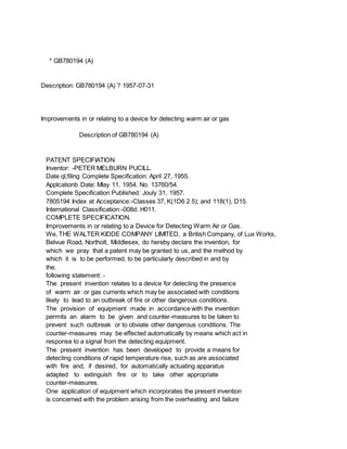
- 2. of large size, unattended amplifiers. Amplifiers are frequently installed in groups in a booth, one or more of the amplifiers being employed only as stand-bys against the failure of one or more of the other amplifiers. The present invention provides a thermally sensitive device which enables incipient failure of an amplifier through overheating to be detected and at the same time provides a means for automatically switching such amplifier out and simultaneously switching a stand-by amplifier in, to take the place of the failure. Simultaneously means of preventing or checking fire in the defective amplifier are brought into action automatically in response to the device. The detector device made in accordance with the present invention has a thermally sensitive element comprising a wire having separate spaced lengths thereof coated with a second metal, one end of each coated portion being arranged in heat conductive relation with and electrically insulated from a relatively large metallic mass and the other end of each coated portion being exposed to the ambient atmosphere. The thermally sensitive element is preferably mounted in a casing into which heated gas or air can penetrate. The apparatus used for detecting overheating in an amplifier is housed in a holder which is arranged directly over the amplifier in the path of the hot air current which will rise from the amplifier in the event of it overheating. The holder is made of insulating plastic material and the top and bottom of the holder are open, a wire grille being provided to protect the thermally sensitive element contained within. Hot air may rise up into the holder through the open bottom s..o as to contact the thermocouple system inside it. One device made in accordance with the present invention is shown in the accompanying drawings, in which:Figure 1 shows an underneath plan view of the complete device with the bottom grille plate removed; and Figure 2 is a section of the thermocouple system. The thermocouple system consists of a coil of "Eureka" (Registered Trade Mark) -ricS!CC, -, metal 1, which is partly plated with copper, each convolution having two copper-plated portions 2 and two plain portions 3. The material of the coil is essentially very light n gauge narrow strip. The coil is substantially rectangular in shape and the plating is applied at two diagonally opposite corners so that 'the copper-plated portions 2 have ends 4 and 4' at approximately the middle of each side of the coil. It is found that if the ends 4 and 4' of a plated portion 2 are maintained at different temperatures, a potential difference is developed between the two ends of the plated portion. The partially plate coil 1 is mounted in the holder 5 directly over
- 3. the bottom opening in the holder so as to be exposed to rising heated air. The coil 1 is mounted on formers 6 made of insulating material and constructed so as to space neighbouring convolutions of the coil apart. The formers 6 are mounted on spacing bolts 7 which also serve to clamp heavy metal blocks 8 and 9 against the formers and the coil 1. The cold junctions at the ends 41 are located so that they are in heat conductive relation with the blocks 8, but they are electrically insulated therefrom by a thin layer of lacquered paper 10. When the air or gas temperature around the thermocouple coil 1 rises with any rapidity, an e.m.f. is developed between the two ends of the coil, because the junctions at the ends 41 in thermal contact with the metal blocks 8 remain at a lower temperature than the junctions at the ends 4 of the plated portions since it takes a little time for the blocks 8 to warm up to the temperature of the surrounding air. The resultant e.m.f. between the two ends of the plated portions are additive since all are in the same direction. The resultant e.m.f. between the two ends of the coil 1 is employed by connecting the terminals 11 to a relay. The whole thermally responsive portion of the device is held away from contact with the surrounding holder 5 and is supported therein by means of clips 12 which engage with the spacing bolts 7. In the particular application of the invention to the fire protection of amplifiers, the relay is employed to energise operator circuits which respectively switch out the faulty amplifier and switch in a stand-by amplifier and also which release CO. to the space around the faulty amplifier so as to prevent fire. The device may equally well be applied for general fire protection purposes, as in the hold of a ship or in a warehouse or factory. Any sudden rise in temperature will cause an e.m.f. to arise between the ends of the coil I and the relay energised thereby may be employed to actuate an alarm and/or to initiate counter-measures. * Sitemap * Accessibility * Legal notice * Terms of use * Last updated: 08.04.2015 * Worldwide Database * 5.8.23.4; 93p