PLC Traffic Light Control
•
11 gostaram•17,801 visualizações

The document describes a ladder logic program for controlling a traffic light system. The system has two switches: one to run the system according to one of two modes (normal or flashing), and another to select the mode. In normal mode, lights are green for 5 seconds and red for 5 seconds, with 1 second for yellow. In flashing mode, lights flash on and off independently. The ladder logic program uses timers, switches, and coils to control the lights according to the two modes.

Recomendados
Mais conteúdo relacionado
Mais procurados
Mais procurados (20)
Semelhante a PLC Traffic Light Control
Semelhante a PLC Traffic Light Control (20)
Mais de Ameen San
Mais de Ameen San (20)
Último
Último (20)
PLC Traffic Light Control
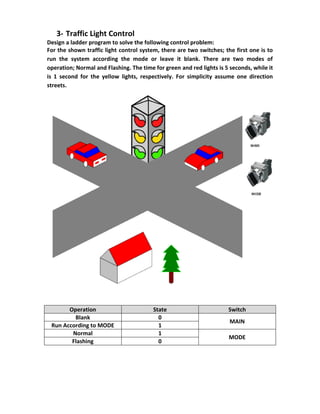
- 1. 3- Traffic Light Control Design a ladder program to solve the following control problem: For the shown traffic light control system, there are two switches; the first one is to run the system according the mode or leave it blank. There are two modes of operation; Normal and Flashing. The time for green and red lights is 5 seconds, while it is 1 second for the yellow lights, respectively. For simplicity assume one direction streets. Operation State Switch Blank 0 MAIN Run According to MODE 1 Normal 1 MODE Flashing 0
- 2. Ladder STL A "Main" A "Mode" CC "Normal"
- 3. A "Main" AN "Mode" CC "Flashing" AN "Main" CC "Blank" FC1 AN T 4 L S5T#5S SE T 3 NOP 0 NOP 0 NOP 0 A T 3 = L 0.0 A L 0.0 BLD 102 = "Red1" A L 0.0 NOT = "Green1" A L 0.0 NOT = "Red2" A L 0.0 BLD 102 = "Green2"
- 4. AN T 3 L S5T#5S SE T 4 NOP 0 NOP 0 NOP 0 NOP 0 A "Green1" L S5T#4S SE T 5 NOP 0 NOP 0 NOP 0 NOP 0 AN T 5 A "Green1" = "Yellow1"
- 5. A "Green2" L S5T#4S SE T 6 NOP 0 NOP 0 NOP 0 NOP 0 AN T 6 A "Green2" = "Yellow2" FC2 AN "Mode" R "Red1" R "Green1" R "Red2" R "Green2"
- 6. AN T 2 L S5T#1S SE T 1 NOP 0 NOP 0 NOP 0 A T 1 = "Yellow1" = "Yellow2" AN T 1 L S5T#1S SE T 2 NOP 0 NOP 0 NOP 0 NOP 0 FC3 AN "Main" R "Red1" R "Yellow1" R "Green1" R "Red2" R "Yellow2" R "Green2"