
Recomendados
Recomendados
Mais conteúdo relacionado
Mais procurados
Mais procurados (8)
Destaque
Semelhante a Raycmltv
Semelhante a Raycmltv (20)
Último
Último (20)
Raycmltv
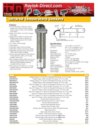
- 1. Infrared temperature Sensors Features: PVC cable ø17 (.67) .75"-16UNF 2A or • Can easily replace traditional contact ø4 (.17) 18M X1 metric thread probes with a J-type or k-typw thermo- couple output, or with a user scaleable ø19 (.75) 0-5V output • Wide -20 to 500°C (-4 to 932°F) temper- 19 73 (2.9) ature range (.75) 94 • Rugged iP 65 (nEMA 4) stainless steel (3.7) mm (inches) housing allows sensor to function in 1m (3.3 ft) cable standard ambient temperatures to 70°C (160°F) Maximum ambient temperature 105°C (220°F) without cooling • 13:1 optics at 90% energy Specifications: • Alarm output Temperature Range: -20 to 500°C (-4 to 932°F) • Adjustable target emissivity settings Accuracy: mV: ±1.5% of reading or ±2°C; • Adjustable window transmissivity setting t/c: ±1.5% of reading or ±4°C • Adjustable signal processing: Peak hold, Repeatbility: ±0.5% of reading or ±2°C Valley hold, variable averaging Resolution: 0.1°C • Sensor status/self-diagnostic LED indicates optical Resolution: 13:1 @ 90% energy normal operation, alarm, out of range, Spectral Response: 8 to 14 microns unstable, sensor fault Response Time: 150mSec • RS-232 digital interface allows user to con- Emissivity: 0.10 to 1.10 (adjustable) figure all programmable sensor variables Transmissivity: 0.10 to 1.00 (adjustable) with Data-Temp Multidrop software, outputs: Type J, Type k or scaleable 0-5V voltage included with each sensor Power: 12 - 24 VDC @ 20 mA output impedance: 100 Ω • Each sensor also includes 1m (3.3 ft) pre- Min. Load impedance: 50 kΩ installed cable, two mounting nuts and Power Supply: 12-24 VDC ±20% @ 10mA Quick Start Guide Digital output: Two-way RS-232 Alarm output: Transistor, 24VDC ±20% <20mA model Description price RAYCMLTV Voltage output, 0.75-16UnF 2A threaded SS housing, 1m (3.3 ft) cable $370 RAYCMLTVM Voltage output, 18Mx1 threaded SS housing, 1m (3.3 ft) cable $370 RAYCMLTV3 Voltage output, 0.75-16UnF 2A threaded SS housing, 3m (10 ft) cable $419 RAYCMLTV3M Voltage output, 18Mx1 threaded SS housing, 3m (10 ft) cable $419 RAYCMLTJ Type J T/C output, 0.75-16UnF 2A threaded SS housing, 1m (3.3 ft) cable $370 RAYCMLTJM Type J T/C output, 18Mx1 threaded SS housing, 1m (3.3 ft) cable $370 RAYCMLTJ3 Type J T/C output, 0.75-16UnF 2A threaded SS housing, 3m (10 ft) cable $419 RAYCMLTJ3M Type J T/C output, 18Mx1 threaded SS housing, 3m (10 ft) cable $419 RAYCMLTK Type k T/C output, 0.75-16UnF 2A threaded SS housing, 1m (3.3 ft) cable $370 RAYCMLTKM Type k T/C output, 18Mx1 threaded SS housing, 1m (3.3 ft) cable $370 RAYCMLTK3 Type k T/C output, 0.75-16UnF 2A threaded SS housing, 3m (10 ft) cable $419 RAYCMLTK3M Type k T/C output, 18Mx1 threaded SS housing, 3m (10 ft) cable $419 XXXCMACMN Stainless Steel Mounting nuts (2) $37 XXXCMACMNM Stainless Steel Mounting nuts (2), Metric Thread $37 XXXCIACFB Stainless Steel Fixed Bracket $57 XXXCIADJB Stainless Steel Adjustable Bracket $88 XXXCMACAP Stainless Steel Air Purge Collar $91 XXXCMACAPM Stainless Steel Air Purge Collar for Metric Threaded Housing $91 XXXCMACRA Right Angle Mirror $157 XXXCMACRAM Right Angle Mirror, Metric Thread $157 XXXCIDCPS 24VDC, 125mA Switching Power Supply $154 XXXCI1CON Thermocouple Cable Extension kit for CMJ Models $50 XXXCI2CON Thermocouple Cable Extension kit for CMK Models $50 RAYGPC 1/8 Din Panel Display & Power Supply $569 XXXCMACPW Protective Silicon Window $107 XXXCMACPWM Protective Silicon Window for Metric Models $107
- 2. CI TWO YEAR LIMITED WARRANTY THERMALERT SERIES Raytek warrants this product to be free from defects in material and workmanship under normal use and service for a period of two years from date of purchase except as hereinafter provided. This warranty extends only to the original purchaser (a purchase from Raytek or Raytek’s licensed distributors is an original purchase). This warranty shall not apply to fuses or batteries. Factory calibra- tion is warranted for a period of one year. The warranty shall not apply to any product which has been subject to misuse, neglect, accident, or abnormal conditions of operation or storage. Should Raytek be unable to repair or replace the product within a reason- able amount of time, purchaser’s exclusive remedy shall be a refund of the purchase price upon return of the product. In the event of failure of a product covered by this warranty, Raytek will repair the instrument when it is returned by the purchaser, freight prepaid, to an authorized Service Facility within the applica- ble warranty period, provided Raytek’s examination discloses to its satisfaction that the product was defective. Raytek may, at its option, replace the product in lieu of repair. With regard to any cov- ered product returned within the applicable warranty period, repairs or replacement will be made without charge and with return freight paid by Raytek, unless the failure was caused by misuse, neglect, accident, or abnormal conditions of operation or storage, in which case repairs will be billed at a reasonable cost. In such a case, an estimate will be submitted before work is started, if requested. THERMALERT® CI™ THE FOREGOING WARRANTY IS IN LIEU OF ALL OTHER WAR- COMPACT INFRARED RANTIES, EXPRESSED OR IMPLIED, INCLUDING BUT NOT LIMITED TO ANY IMPLIED WARRANTY OF MERCHANTABILI- SENSOR TY, FITNESS, OR ADEQUACY FOR ANY PARTICULAR PURPOSE OR USE. RAYTEK SHALL NOT BE LIABLE FOR ANY SPECIAL, INCIDENTAL OR CONSEQUENTIAL DAMAGES, WHETHER IN OPERATOR’S GUIDE CONTRACT, TORT, OR OTHERWISE. Raytek, the Raytek Logo, and Thermalert are registered trademarks and CI is a trademark of Raytek Corporation Rev J 05/00 © Copyright 1996-2000 by Raytek Corporation 56800-1 THERMALERT CI ACCESSORIES The Thermalert® CI™ Compact Infrared Sensor series A full range of accessories for various applications and of online instruments are noncontact infrared tempera- industrial environments are available (see Figure 1). ture measurement systems. They are designed to meas- Accessories may be ordered at any time and added ure accurately and repeatably the amount of heat ener- on-site. Also available is a J- or K-type thermocouple gy emitted from an object and to convert that energy connection kit and extension cables. into a measurable electrical signal. Each model (see Table 1) comes with a 1 m (3 ft) cable and two mounting nuts and is designed for easy inte- Adjustable mounting bracket accessory gration into standard 4-wire systems. There are J or K thermocouple output models or 10 mV/°C voltage out- Fixed put models if your application is susceptible to noise or mounting bracket Mounting nuts requires a long cable run. The electronics are protected (2 supplied) accessory by a rugged NEMA 4 stainless steel housing. Sensor Table 1: Models Overall Air purge collar Model Output Temp. Range Accuracy accessory J Thermocouple 0 to 115˚ C (32 to 240˚ F) Sensor CI1A larger of ±2% or ± 3 ˚ C (± 6 ˚ F) 0 to 350˚ C 116 to 225˚ C (241 to 440˚ F) CI2A K Thermocouple Right angle mirror (32 to 662˚ F) larger of ± 5 % or ± 6 ˚ C (± 1 0˚ F) accessory CI3A Voltage 226 to 350˚ C (441 to 662˚ F) >±5% Air/Water-cooled housing with integrated air purge CI1B J Thermocouple (factory installed option) 100 to 500˚ C (212 to 932˚ F) larger of ± 2 % or ± 3 ˚ C (± 6 ˚ F) 30 to 500˚ C CI2B K Thermocouple (86 to 932˚F) 30 to 99˚ C (86 to 211˚ F) larger of ± 5 % or ± 6 ˚ C (± 1 0˚ F) Figure 1: Accessories and Options CI3B Voltage 1 2
- 3. OPTIONS Table 2 (continued): Specifications Options for various applications and environments Electrical are available. Options are factory installed and must Power supply voltage 12 – 24 VDC @20 mA be ordered with base model units. These include the Maximum current draw ≤ 10 mA Ripple ≤ 2.5% following: Output impedance 50 ohms • NIST traceable certification Minimum load impedance 50K ohms • Air/Water-cooled housing (comes with integrated Outputs J or K thermocouple, air purging and high temperature cable) 10mV/˚C Linear Voltage • High temperature cable–260°C (500°F) maximum Environmental ambient temperature (comes standard with Sensing head rating IP 65, NEMA 4 air/water-cooled housing option) EMI Conducted noise immunity IEC 801-4, Level 1 • Longer 3 m (10 ft) standard cable Relative humidity 10 to 95%, non-condensing Storage temp. range -30 to 85˚ C (-22 to 185˚ F) SPECIFICATIONS Thermal shock Max error of 5˚ C (for ∆T=25˚) Table 2 (below and continued on Page 4) lists the sen- stabilization time=20 mins. Ambient operating range 0 to 70˚ C (32 to 160˚ F) sor’s optical, thermal, operational, electrical, environ- air cooling 0 to 94˚ C (32 to 200˚ F) mental, and physical specifications. water cooling 0 to 105˚ C (32 to 220˚ F) water cooling/high temp cable 0 to 260˚ C (32 to 500˚ F) Table 2: Specifications Physical Dimensions 19 mm dia x 87 mm L Optical Resolution 4:1 @ 90% energy (0.75 in dia x 3.4 in L) Spectral Response Range 7–18 µm Weight 130 g (4.5 oz) Material Stainless steel Thermal Measurement range See Table 1 Cable–Standard Detecting element Thermopile Maximum ambient temperature 105˚ C (220˚ F) Accuracy See Table 1 Material (type & color) PVC, grey Cable length 1 m (3 ft) Repeatability ±1% of reading Gauge AWG 24 (J, K t/c cable) Temperature coefficient 0.2˚ C per ˚C (0.2˚ F per ˚F) AWG 22 (10mV/˚C cable) Operational Cable–High Temperature Temperature resolution < 0.5˚ C (1˚ F) Maximum ambient temperature 260˚ C (500˚ F) Emissivity Fixed at 0.95 Material (type & color) Teflon, black Response time 350 mSec (95% response) Cable length 1 m (3 ft) Warm-up period < 1 minute Gauge AWG 24 Continued on next page 3 4 Optical Chart INSTALLATION Figure 2 shows you how to read the optical chart. The The installation process consists of the following: optical chart (Figure 3) indicates the nominal target • Preparation spot diameter at any given distance from the sensing • Mechanical Installation head and assumes 90% energy. • Electrical Installation Target spot size Diameter of target Distance from sensor The most important part of the installation process is at focus point spot size in inches to object in inches or feet preparation. Please read the following section thor- oughly before proceeding with the mechanical and electrical installations. Preparation Distance and Spot Size—The size of the area (spot size) you wish to measure determines the distance between the sensor and the target (see Figure 3 for dis- tances and spot sizes). The spot size must not be larg- er than the target. Mount the sensor so the measured Diameter of target spot is the same or smaller than the target. Figure 4 is Distance from sensor to spot size in millimeters object in millimeters or meters an overview of proper sensor placement. Focus Point D:S = Distance to spot divided by spot diameter at the focus point Far Field D:S = Ratio at distances greater than 10x the focus distance Best Good Incorrect Figure 2: How to Read the Optical Chart Sensor Target greater than spot size Target equal Background to spot size Target smaller than spot size Figure 3: Optical Chart Figure 4: Proper Sensor Placement 5 6
- 4. Ambient Temperature—The sensing head is designed Mechanical Installation to operate in ambient temperatures from 0 to 70°C (32 All sensors come with a 1 m (3 ft) cable and 2 mount- to 160°F). For ambient temperatures above 70°C ing nuts. You can mount the sensor in brackets or (160°F), a factory installed air/water-cooled housing cutouts of your own design, or you can use the fixed option is available that allows operation in ambient and adjustable mounting bracket accessories. Figures conditions up to 260°C (500°F) with water cooling. 5 through 7 show the mounting bracket accessories’ The air/water-cooled housing option comes with a and sensor’s dimensions. high-temperature cable and integrated air purging. Full R Atmospheric Quality—Smoke, fumes, dust, and other contaminants can coat the lens and cause erroneous ∅19 (.76) temperature readings. We recommend using the air purge collar accessory in these types of environments to keep the lens clean. (The air/water-cooled housing 38 (1.5) comes with integrated air purging.) 1.5 22 (.06) (.875) Electrical Interference—To minimize electrical or elec- tromagnetic interference or “noise,” mount the sensor 38 away from motors producing large step load changes. (1.5) 5 Wiring—Before installing, be sure to check the dis- (.196) tance between the sensor and the monitoring/control- ∅5 (.196) ling device. If necessary, extension cables are available as accessories. 2X 45˚ 2X 90˚ 38 Power—Have available a 12–24 VDC, 10 mA, power (1.5) supply. 2X 13 19 (2X .5) (.75) 38 (1.5) mm (inches) Figure 5: Fixed Mounting Bracket 7 8 Air/Water-cooled Housing with integrated air purge— 41 (1.625) 5 The air/water-cooled housing option (Figure 8) allows (.196) 22 ∅5 (.196) the sensor to withstand ambient temperatures up to (.875) 260° C (500° F) with water cooling and the high-temper- 2X 45˚ ature cable. (The high-temp cable is standard when the 2X 90˚ 38 housing is ordered as an option.) It has 1/8” NPT fit- (1.5) tings for water and air. Water temperature should be 59 (2.31) 15-30° C (60-86° F) for best performance. Chilled water ∅19 (.76) below 10° C (50° F) is not recommended. Without the Full R 2X 13 19 high-temperature cable, the sensor can withstand ambient (.75) (2X .5) temperatures only up to 105° C (220° F) with water cooling. 38 (1.5) ∅38 (1.5) ∅38 (1.5) 38 (1.5) mm (inches) ∅20 (0.8) 3/4"–16UNF 2A Figure 6: Adjustable Mounting Bracket 13 flats (0.5) 1 m (3 ft) 3/4"–16UNF 2A Front View Rear View PVC Cable ∅17 (.67) M18 x 1 (if ordered metric) ∅4 (.17) 10 96 12 (0.39) (3.79) (0.45) ∅14 (.56) ∅19 (.75) 1/8" NPT fittings (3) 19 63 7 (.75) (2.48) (.27) 89 (3.5) mm (inches) Figure 7: Sensor 6 ~ 25 ~ 13 (0.25) (~ 1) (~ 0.5) 25 (1) 118 (4.63) 137 (5.38) mm (inches) Figure 8: Air/Water-cooled Housing 9 10
- 5. Air Purge Collar—The air purge collar accessory Right Angle Mirror—The right angle mirror accessory (Figure 9) is used to keep dust, moisture, and other (Figure 10) allows a perpendicular view of a target. It contaminants away from the lens. It must be screwed may be used when space is limited or when you need in fully. Air flows into the 10/32” fitting and out the to avoid excessive radiation to the sensor. This can be front aperture. Clean or “instrument” air is recom- mounted either on the end of the sensor or on the air mended. The air purge collar accessory is not needed with purge collar, but not on the air/water-cooled housing. the air/water-cooled housing. Note: When using the right angle mirror, a small ∅35 Inside threads M18 x 1 (if ordered with metric threaded sensor) amount of energy emitted by the source is lost, which (1.38) results in a lower than actual temperature reading. To ∅19 (0.75) 3/4" – 16UNF 2A compute the corrected temperature, use this formula: 10/32" threads 35 T = 1.035Tm – .035Tamb (1.36) where T=corrected temperature, Tm=temperature read- ~ 25 ing with mirror, and Tamb=ambient temperature. All (~ 1) 61 11 (0.42) 9 temperatures are in either °C or °F. (2.38) 21 (0.37) (0.84) ∅20 (.8) 31 (1.21) mm (inches) 3/4"–16 UNF 2B Figure 9: Air Purge Collar Table 3: Recommended Water and Air Recommended Cooling water supply Temperature 15–30˚ C (60–86˚ F) 82 Flow rate 1.89 liters per min (0.5 gpm) Pressure drop (across unit only) < 0.69 bar (10 psi) 13 (.5) Cooling air supply Temperature < 30˚ C (< 86˚ F) Flow rate 70.8 liters per minute (2.5 SCFM) Pressure drop 20 (.8) (across unit only) < 0.34 bar (5 psi) Air purge air supply Temperature < 30˚ C (< 86˚ F) Flow rate 11.33 liters per minute (0.4 SCFM) 31 (1.25) mm (inches) Pressure drop (across unit only) < 0.34 bar (5 psi) Figure 10: Right Angle Mirror 11 12 Wiring—Wire the electronics cable using Figure 11 and Electrical Installation Table 4 or 5 (for high temp cables) as a guide. USE ONLY THE OUTPUT TYPE OF YOUR SENSOR. Sensor to Electronics Cable—The sensor to electron- WIRING TO THE WRONG OUTPUT WILL DAM- ics cable is a 1m (3 ft), 4-wire, PVC cable. One end is AGE THE SENSOR. Note in Figure 11 that the num- attached, at the factory, to the sensor head. The bers refer to the wire numbers in Table 4 or 5, which other end has two pairs of wires and a bare shield shows proper wiring connections based on insulation (ground) wire (see Figure 11). color coding. NOTE LABEL Wire Numbers The unlabeled pair of wires is for connecting to a (ON POWER (Refer to Table 4 or 5) controller or chart recorder or for attaching to a ther- SUPPLY WIRES ONLY) 1 mocouple plug (for connecting to a thermocouple 2 meter). DO NOT CONNECT TO A POWER SOURCE. Red (+) 3 The second pair of wires, with the label, is for con- necting to a power source. 4 12 – 24 VDC 5 (Shield) WARNING Figure 11: Wiring Configuration Incorrect wiring will cause severe, per- Table 4: Standard Cable Wiring manent damage to the sensor. Wire Output Label Number Wire Color Function Pay close attention to the wiring diagram in Output 1 White Signal + (Iron) Figure 11, and match your sensor to the appropri- J-type 2 Red (white stripe) Signal – (Constantan) ate output type in Table 4 or 5. Wire accordingly. Thermo- couple Power 3 Red (yellow stripe) Power Supply + Supply 4 Yellow Power Supply – DO NOT CONFUSE OUTPUT WIRES WITH – 5 Bare Shield Ground POWER SUPPLY WIRES. Output 1 Yellow Signal + (Chromel) K-type 2 Red (yellow stripe) Signal – (Alumel) Thermo- Power 3 Red (white stripe) Power Supply + couple Supply 4 White Power Supply – – 5 Bare Shield Ground Output 1 White Signal + 10mV/˚C 2 Green Signal Ground Voltage Power 3 Red Power Supply + Supply 4 Black Power Supply – – 5 Bare Shield Ground 14 13
- 6. Table 5: High Temperature Cable Wiring OPERATION Wire Once the sensor is in position and you have made sure Output Label Number Wire Color Function that the appropriate power, air, water, and cable con- Output 1 White Signal + (Iron) J-type 2 Red (white stripe) Signal – (Constantan) nections are secure, the system is ready for continuous Thermo- couple Power 3 Red Power Supply + operation. Supply 4 Yellow Power Supply – – 5 Bare Shield Ground To operate, complete the following simple steps: Output 1 Yellow Signal + (Chromel) K-type 2 Red Signal – (Alumel) 1. Turn on the power supply. Thermo- Power 3 Red (white stripe) Power Supply + couple Supply 4 White Power Supply – 2. Turn on the meter, chart recorder, or controller. – 5 Bare Shield Ground 3. Read/monitor the temperature. Output 1 Red Signal + 10mV/˚C 2 Yellow Signal Ground Voltage Power 3 Red (white stripe) Power Supply + Supply 4 White Power Supply – WARNING – 5 Bare Shield Ground If using the air/water-cooled housing, do not leave it in a heated environment with the Extension Cables—Extension cables are available as coolant turned off. Damage to the sensor and to accessories. Also available is a thermocouple connec- the housing can occur. tion kit. IMPORTANT MAINTENANCE AND Be aware of the following when using the sensor: TROUBLESHOOTING • If the sensor is exposed to significant changes in If your sensor is not performing as it should, try to ambient temperature (hot to cold or cold to hot), match the symptom in Table 6 to its probable cause. If allow 20 minutes for the temperature to stabilize the table does not help, call us at one of the phone before taking or recording measurements. numbers listed on the last page. • Do not operate the sensor near large electrical or Our customer service representatives are always at magnetic fields (e.g., around arc welders or induc- your disposal for application assistance, calibration, tion heaters). Electro-Magnetic Interference (EMI) repair, and solutions to specific questions or problems. can cause measurement errors. Contact our Service Department before returning any • Connectors or wires must be connected only to the equipment to us. In many cases, problems can be appropriate input jacks or terminals. solved over the telephone. 15 16 Table 6: Troubleshooting Symptom Probable Cause Solution No output No power to sensor Check the power supply Erroneous Temp. Incorrect wire Check wire color connection codes and reconnect Raytek Corporation Worldwide Headquarters Faulty sensor cable Verify cable continuity Box 1820, Santa Cruz, CA 95061-1820 Erroneous Temp. Phone: (831) 458-1110 (800) 227-8074 FAX: (831) 458-1239 Erroneous Temp. Field of view Remove obstruction obstruction Raytek GmbH European Headquarters Lens Cleaning—Keep the lens clean at all times. Blow Phone: 49 30 478 0080 FAX: 49 30 471 0251 off loose particles (if not using the air purge accessory) with clean compressed air, then carefully wipe surface Raytek do Brasil with moist cotten swab (water or water-based glass South American Headquarters Phone: 55 15 233 6338 cleaner). DO NOT use solvents. FAX: 55 15 233 6826 Raytek Mexico CE CONFORMITY FOR THE Mexico, Caribbean, and Central America Phone: 52 22 30 4380 EUROPEAN COMMUNITY FAX: 52 22 30 4438 Raytek Japan, Inc. Phone: 81 3 3822 5715 FAX: 81 3 3822 5712 This instrument conforms to the following standards: Raytek China Company Phone: 86 10 6437 0284 • EN50081-1:1992, Electromagnetic Emissions FAX: 86 10 6437 0285 • EN50082-1:1992, Electromagnetic Susceptibility Raytek UK Ltd. Phone: 441 908 630800 Emission tests were conducted over a frequency range FAX: 441 908 630900 of 30–1000 MHz and susceptibility tests over a range Raytek France of 27–500 MHz . The instrument’s average error in Phone: 33 1 64 53 1540 these frequency ranges is 1.0° C at an electric field FAX: 33 1 64 53 1544 strength of 3 V/m. At some frequencies the instru- ment may not meet its stated accuracy. 17
- 7. CM Noncontact Temperature Measurement for Industrial Applications & OEMs
- 8. CM Highlights Measurement Specifications ■ Scaleable 0-5 V, type J or K output Temperature Range -20ºC to 500ºC (-4ºF to 932ºF) 1,2 ■ ide -20°C to 500°C (-4°F to 932°F) W Accuracy (mV) ± 1.5% of reading or ± 2ºC, whichever is greater temperature range Accuracy (t/c) ± 1.5% of reading or ± 4ºC, whichever is greater1,2,3 ■ Rugged IP 65 (NEMA-4) Spectral Response 8 to 14 microns stainless steel housing ■ Rugged 13:1 optics at 90% energy System Repeatability ± 0.5% of reading or ± 2ºC, whichever is greater ■ 150 mSec (95%) response time Temperature Resolution 0.1°C ■ Alarm output Response Time (95%) 150 mSec ■ ensor status/self diagnostic S Emissivity 0.10 to 1.10 (adjustable) indicator LED ■ S232 digital communications for R Transmissivity 0.10 to 1.00 (adjustable) sensor set-up and monitoring Signal Processing Peak hold, valley hold, variable averaging ■ Adjustable signal processing ® Self diagnostics/sensor status Normal operation, alarm, out of range, unstable, ■ DataTemp Multidrop sensor fault software compatible ■ ccessories for air purging and Bore-Sight tolerance 4 3º @ focal point A 1 lens protection Accuracy from -20 to 0ºC is ±3.5ºC 2 Accuracy and resolution specifications are valid for ambient temperature The Raytek® CM sensor provides the 23ºC ± 5ºC, e = 1.0 calibration geometry advantages of infrared temperature 3 Accuracy measured on the 0-5 VDC output or RS232 for t/c models is ± 1.5% measurement in a powerful, compact, of reading or ± 2ºC, whichever is greater integrated sensor. Designed for easy integration, the CM sensor can easily 4 Typical values measured at focal distance replace traditional contact probes with a J-type or K-type thermocouple output, or with a user scaleable 0-5 volt output, if your application is susceptible to noise. The CM sensor is designed to measure target temperatures ranging from -20°C to 500°C (-4°F to 932°F). The CM's onboard electronics are protected by a rugged IP 65 (NEMA-4) stainless steel housing, allowing the sensor to function in ambient temperatures to 70°C (160°F) without cooling. Nominal Optical Specifications Although small in size, the CM is loaded with advanced features. An RS232 digital D:S=13:1 at focal point Far field D:S=9:1 interface allows the user to configure all programmable sensor variables with the powerful DataTemp Multidrop software included with each sensor. These include a 24 volt DC alarm output triggered by target temperature or head ambient temperature, peak hold, valley hold or variable averaging signal processing, adjustable target emissivity settings and adjustable window transmissivity setting. The built-in sensor health LED provides a convenient on-line indicator of the sensor's operating status and aids in D:S is the optical resolution expressed as a ratio of the distance to the target troubleshooting initial sensor set up. spot divided by the diameter of the spot. Compact. Powerful. Easy to install. Nominal spot size based on 90% energy. Affordable. The Raytek CM sensor is the ideal solution for both OEM and end-user applications.
- 9. Electrical Specifications Analog Outputs Model specific Type J, Type K or scaleable 0-5V voltage output Cable Length (3.3 ft) standard 1m 3m (9.8 ft) cables optional Thermocouple Output Impedance 100 ohms Voltage Output Minimum Load Impedance 50K ohms Power Supply 12–24 VDC ±20% @ 10mA Digital Output 5 Accessories Options Two-way RS232 digital output 5 Alarm Output Transistor, 24VDC ±20% 20mA 5 Digital output and alarm output share a common wire. Each CM sensor includes two mounting nuts, 1m (3.3ft.) of cable, User selects either alarm output or RS232 communication and a quick start guide. 3m (9.8ft) cables are also available. via Datatemp Multidrop software. Sensor Specifications Adjustable or fixed mounting bracket for Environmental Rating IP 65 (NEMA-4) sensing head (XXXCIADJB A bient Temperature Range 0ºC to 70°C (32ºF to 160°F) m or XXXCIACFB) Cable Temperature Range -30ºC to 105ºC (-22ºF to 220ºF) Storage Temperature -20ºC to 85°C (-4ºF to 185°F) Relative Humidity 10 to 95%, non-condensing Shock IEC 68-2-27 (MIL STD 810D) 50 g’s, 11 mSec, any axis Vibration IEC 68-2-27 (MIL STD 810D) ir purge jacket to keep lens A 3 g’s, any axis, 11–200 Hz or right angle mirror clean (XXXCMAP or XXXCMAPM Weight 1m cable model: 145 g (5.1 oz) for metric version) Sensor Dimensions Protective lens covering (XXXCMACPW or XXXCMACPWM) 94 (3.7) Right angle mirror to ease installation into tight locations (XXXCMACRA or XXXCMACRAM)
- 10. Model Description RAYCMLT Raytek infrared temperature sensor Code A Output A B C J Type J Thermocouple Output K Type K Thermocouple Output RAYCMLT V Voltage Output (Linear, scaleable from 0-5V) Code B Cable Length Output Cable Housing Length Thread 1M (3.3ft) Cable 3 3M (9.8ft) Cable Code C Housing thread Typical Model RAYCMLTV3 Standard 0.75-16 UNF Number M 18 MX1 Metric Accessory Dimensions 2 41 (0.08) (1.625) 5 22 (.196) (.875) 5 (.196) 2X 45º 40 2X 90º (1.52) 59 Full R (2.31) 19 (.76) 2X 13 19 (.76) Full R (2X .50) 19 (.75) 38 38 (1.5) (1.5) 1.5 22 39 (.06) (.875) (1.54) Adjustable Mounting Bracket 38 (1.5) 5 (.196) Air purge collar 5 (.196) 2X 45∞ 2X 90º 38 (1.5) MI8 #1 21 3/4-16 UNF-2B (.83) 2X 13 19 (2X .5) (.75) 38 (1.5) mm (inches) 15.5 (.61) Fixed Mounting Bracket Protective Window Right angle mirror The Worldwide Leader in Noncontact Temperature Measurement Raytek Corporation Worldwide Headquarters Santa Cruz, CA USA Tel: 1 800 227 8074 (USA and Canada, only) www.raytek.com 1 831 458 3900 solutions@raytek.com European Headquarters Berlin, Germany France United Kingdom Tel: 49 30 4 78 00 80 Tel: 0800 888 244 Tel: +44 1908 630 800 raytek@raytek.de info@raytek.fr ukinfo@raytek.com China Headquarters Beijing, China Tel: 8610 6438 4691 info@raytek.com.cn To find a Raytek office near you, please visit www.raytek.com Worldwide Service Raytek offers services, including repair and calibration. For more information, contact your local office or e-mail support@raytek.com © 2009 Raytek Corporation (3449292 Rev. A) 4/2009 Raytek, the Raytek logo and Datatemp are registered trademarks of Raytek Corporation. Specifications subject to change without notice.
- 12. Contacts Raytek Corporation Santa Cruz, CA USA Tel: +1 800 227 – 8074 or +1 831 458 – 3900 Fax: +1 831 458 – 1239 solutions@raytek.com Raytek GmbH Berlin, Germany Tel: +49 30 478008 – 0 Fax: +49 30 4710251 raytek@raytek.de Fluke Beijing Service Center Sales and technical support line (Raytek): (8610) 64384691 Service line: (8610) 4008103435 Service fax line: (8610) 65286307 Info@raytek.com.cn United Kingdom Raytek Japan, Inc. ukinfo@raytek.com info@raytekjapan.co.jp France info@raytek.fr © Raytek Corporation. Raytek is a registered trademark of Raytek Corporation. All rights reserved. Specifications subject to change without notice.
- 13. WARRANTY The manufacturer warrants this product to be free from defects in material and workmanship under normal use and service for a period of two years from date of purchase except as hereinafter provided. This warranty extends only to the original purchaser. This warranty shall not apply to fuses or batteries. Factory calibration is warranted for a period of one year. The warranty shall not apply to any product that has been subject to misuse, neglect, accident, or abnormal conditions of operation or storage. Should the manufacturer be unable to repair or replace the product within a reasonable amount of time, purchaser’s exclusive remedy shall be a refund of the purchase price upon return of the product. In the event of failure of a product covered by this warranty, the manufacturer will repair the instrument when it is returned by the purchaser, freight prepaid, to an authorized Service Facility within the applicable warranty period, provided the manufacturer’s examination discloses to its satisfaction that the product was defective. The manufacturer may, at its option, replace the product in lieu of repair. With regard to any covered product returned within the applicable warranty period, repairs or replacement will be made without charge and with return freight paid by the manufacturer, unless the failure was caused by misuse, neglect, accident, or abnormal conditions of operation or storage, in which case repairs will be billed at a reasonable cost. In such a case, an estimate will be submitted before work is started, if requested. THE FOREGOING WARRANTY IS IN LIEU OF ALL OTHER WARRANTIES, EXPRESSED OR IMPLIED, INCLUDING BUT NOT LIMITED TO ANY IMPLIED WARRANTY OF MERCHANTABILITY, FITNESS, OR ADEQUACY FOR ANY PARTICULAR PURPOSE OR USE. THE MANUFACTURER SHALL NOT BE LIABLE FOR ANY SPECIAL, INCIDENTAL OR CONSEQUENTIAL DAMAGES, WHETHER IN CONTRACT, TORT, OR OTHERWISE.
- 14. T ABLE OF C ONTENTS 1 Safety Instructions............................................................................................................................................................... 1 2 Description .............................................................................................................................................................................. 2 3 Technical Data ....................................................................................................................................................................... 3 3.1 PARAMETERS .....................................................................................................................................................3 3.2 OPTICAL DIAGRAM .............................................................................................................................................4 3.3 SCOPE OF DELIVERY ..........................................................................................................................................4 4 Basics ........................................................................................................................................................................................ 5 4.1 MEASUREMENT OF INFRARED TEMPERATURE ..................................................................................................5 4.2 SIGHT..................................................................................................................................................................5 4.3 AMBIENT TEMPERATURE ....................................................................................................................................5 4.4 ATMOSPHERIC QUALITY .....................................................................................................................................5 4.5 ELECTRICAL INTERFERENCE ..............................................................................................................................6 4.6 EMISSIVITY OF TARGET OBJECT ........................................................................................................................6 5 Install and Operation........................................................................................................................................................... 7 5.1 DIMENSIONS OF SENSOR ...................................................................................................................................7 5.2 MECHANICAL INSTALLATION...............................................................................................................................7 5.3 CABLE .................................................................................................................................................................8 5.4 WIRE CONNECTION ............................................................................................................................................8 5.4.1 Analog output ........................................................................................... 8 5.4.2 Alarm output ............................................................................................. 8 5.5 LED INDICATOR AND BLINK MODE ......................................................................................................................9 6 Software.................................................................................................................................................................................. 10 7 Accessories .......................................................................................................................................................................... 11 7.1 OVERVIEW ........................................................................................................................................................11 7.2 FIXED MOUNTING BRACKET .............................................................................................................................12 7.3 ADJUSTABLE MOUNTING BRACKET..................................................................................................................12 7.4 AIR PURGE COLLAR .........................................................................................................................................13 7.5 RIGHT ANGLE MIRROR .....................................................................................................................................14 7.6 PROTECTIVE WINDOW .....................................................................................................................................14 8 Programming........................................................................................................................................................................ 15 8.1 GENERAL COMMAND STRUCTURE ...................................................................................................................15 8.2 DEVICE SETUP .................................................................................................................................................15 8.2.1 Temperature Calculation ...................................................................... 15 8.2.2 Post Processing..................................................................................... 15 8.3 DYNAMIC DATA .................................................................................................................................................16 8.4 DEVICE CONTROL ............................................................................................................................................16 8.4.1 Controlling the output for the target temperature.............................. 16 8.4.2 Analog output, scaling .......................................................................... 16 8.4.3 Alarm output ........................................................................................... 16 8.4.4 Factory default values........................................................................... 16 9 Maintenance.......................................................................................................................................................................... 17 9.1 TROUBLESHOOTING MINOR PROBLEMS ..........................................................................................................17 9.2 ERROR CODES .................................................................................................................................................17 9.3 AUTOMATIC ERROR INDICATION ......................................................................................................................17 9.4 CLEANING THE LENS ........................................................................................................................................18 9.5 REPLACING A PROTECTIVE WINDOW ...............................................................................................................18 10 Appendix.............................................................................................................................................................................. 19 10.1 DETERMINATION OF EMISSIVITY ....................................................................................................................19 10.2 TYPICAL EMISSIVITY VALUES .........................................................................................................................19 10.3 COMMAND SET ...............................................................................................................................................22
- 15. Operation Manual 1 Safety Instructions This document contains important information, which should be kept at all times with the instrument during its operational life. Other users of this instrument should be given these instructions with the instrument. Eventual updates to this information must be added to the original document. The instrument can only be operated by trained personnel in accordance with these instructions and local safety regulations. Acceptable Operation This instrument is intended only for the measurement of temperature. The instrument is appropriate for continuous use. The instrument operates reliably in demanding conditions, such as in high environmental temperatures, as long as the documented technical specifications for all instrument components are adhered to. Compliance with the operating instructions is necessary to ensure the expected results. Unacceptable Operation The instrument should not be used for medical diagnosis. Replacement Parts and Accessories Use only original parts and accessories approved by the manufacturer. The use of other products can compromise the operational safety and functionality of the instrument. Instrument Disposal Disposal of old instruments should be handled according to professional and environmental regulations as electronic waste. Operating Instructions The following symbols are used to highlight essential safety information in the operating instructions: Helpful information regarding the optimal use of the instrument. Warnings concerning operation to avoid instrument damage. Warnings concerning operation to avoid personal injury. Pay particular attention to the following safety instructions. Use in 110 / 230 V electrical systems can result in electrical hazards and personal injury if not properly protected. All instrument parts supplied by electricity must be covered to prevent physical contact and other hazards at all times. 1 Raytek CM
- 16. Operation Manual 2 Description The CM miniature infrared sensors are high performance noncontact infrared temperature measurement systems. They measure the amount of energy emitted from an object accurately and repeatedly and convert the energy into temperature signal. The following analog outputs are available by different model: • 0-5Volt • J -Thermocouple • K-Thermocouple The LED on the back of CM shows the status of units. RAYCMLT * # Output Cable Length Thread Model Description RAYCMLT Raytek infrared temperature sensor * Output V Voltage Output (Linear, scaleable from 0-5V) J Type J Thermocouple output K Type K Thermocouple output # Cable Length 1M (3.3ft) Cable 3 3M (9.8ft) Cable Thread UNF thread M metric thread Typical Model Number RAYCMLTV3 Raytek CM 2
- 17. Operation Manual 3 Technical Data 3.1 Parameters Temperature range (℃) -20 … 500℃ Temperature range (℉) -4 … 932℉ Optical resolution 13:1 @ 150mm (90% energy) Spectral response 8 … 14μm Thermal Parameters Accuracy(Digital and Voltage)* ±1.5% of reading or ±2℃, whichever is greater Accuracy (TC)* ±1.5% of reading ±2℃ ,or ±4℃, whichever is greater Repeatability(Digital and Voltage) ±0.5% of reading or ±1℃, whichever is greater Repeatability(TC) ±0.5% of reading ±1℃ ,or ±2℃, whichever is greater Response time (95% energy) 150 ms Temperature resolution 0.1℃ (0.2℉) Emissivity 0.100 … 1.100 (adjustable) Transmissivity 0.100 … 1.000 (adjustable) Electrical Parameters Digital Output ** Two-way RS232 digital output Analog Output 0 to 5 V or TCJ or TCK output Alarm Output ** Transistor, 24VDC @ 20mA Power 24VDC± 20% @ 20mA General Parameters Environmental rating IP 65 (NEMA-4x) Ambient operating range -10 to 70℃ Storage temperature -20 to 85℃ Dimensions / Weight L: 94 mm; Ø: 19 mm / 200g Specifications subject to change without notice. *Accuracy(Digital and Voltage) from –20 to 0℃ is ± 3.5℃. Accuracy(TC) from –20 to 0℃ is ± 5.5℃. Accuracy measured at ambient temperature 23℃±5℃, e = 0.95 and calibration geometry. ** RS232 TxD and Alarm output share one single wire. Either can be selected by DataTemp or RS232 command. Declaration of Conformity for the European Community This instrument conforms to the following standards: EMC: EN61326‐1:2006 Safety: EN61010‐1:2001 3 Raytek CM
- 18. Operation Manual 3.2 Optical Diagram D: S @ focus point= 13:1 / 11.5mm @ 150mm D = Distance from sensor to target S = Spot Diameter (@90% energy) DISTANCE: SENSOR TO OBJECT(mm) SPOT DIA.(mm) D:S SPOT DIA.(in) DISTANCE: SENSOR TO OBJECT(in) Figure 1: How to read the optical diagram Calculating the Target Spot Size To calculate the target spot size from two known points within an optical diagram the following formula can be used: ⎡ (D − D n ) ⎤ S x = Sn + ⎢ x ⋅ (Sf − S n )⎥ ⎣ (D f − D n ) ⎦ Sx = unknown diameter of target spot Sn = smallest known diameter of target spot Sf = greatest known diameter of target spot Dx = distance to unknown target spot Dn = distance to smaller known target spot Df = distance to greater known target spot 3.3 Scope of Delivery All models are provided with: Mounting nuts Support software CD Quickstart Guide Raytek CM 4
- 19. Operation Manual 4 Basics 4.1 Measurement of Infrared Temperature Everything emits an amount of infrared radiation according to its surface temperature. The intensity of the infrared radiation changes according to the temperature of the object. Depending on the material and surface properties, the emitted radiation lies in a wavelength spectrum of approximately 1 to 20 µm. The intensity of the infrared radiation (”heat radiation”) is dependent on the material. For many substances this material-dependent constant is known. It is referred to as the ”emissivity value”, see 10.2 Typical Emissivity Values on page 19. Infrared thermometers are optical-electronic sensors. These sensors are able to detect ”radiation of heat”. Infrared thermometers are made up of a lens, a spectral filter, a sensor, and an electronic signal- processing unit. The task of the spectral filter is to select the wavelength spectrum of interest. The sensor converts the infrared radiation into an electrical parameter. The connected electronics generate electrical signals for further analysis. As the intensity of the emitted infrared radiation is dependent on the material, the required emissivity can be selected on the sensor. The biggest advantage of the infrared thermometer is its ability to measure in the absence of contact. Consequently, surface temperatures of moving or hard to reach objects can easily be measured. 4.2 Sight To assure the target is bigger than the spot size, the distance between the sensor and the target should be nearer for a smaller target. Refer to the diagram below. Best Good Incorrect Sensor Target greater than spot size Target equal Background to spot size Target smaller than spot size Figure 2: Proper Sensor Placement 4.3 Ambient Temperature The sensing head should work under ambient operating range in Technical Data. 4.4 Atmospheric Quality In order to prevent damage to the lens and erroneous readings, the lens should always be protected from dust, smoke, fumes, and other contaminants. For this purpose an air purge collar is available. You should only use oil free, clean “instrument“ air. 5 Raytek CM
- 20. Operation Manual 4.5 Electrical Interference To minimize electrical or electromagnetic interference, follow these precautions: Mount the sensor as far away as possible from possible sources of interference such as motorized equipment producing large step load changes. Ensure a fully insulated installation of the sensor (Avoid ground loops!). Make sure the shield wire in the sensor cable is earth grounded at one location. Don’t connect 24V power wire directly to the power network to avoid possible noise effect from it. 4.6 Emissivity of Target Object Determine the emissivity of the target object as described in appendix 10.1 Determination of Emissivity on page 19. If emissivity is low, measured results could be falsified by interfering infrared radiation from background objects (such as heating systems, flames, fireclay bricks, etc. close beside or behind the target object). This type of problem can occur when measuring reflecting surfaces and very thin materials such as plastic films and glass. This measuring error when measuring objects with low emissivity can be reduced to a minimum if particular care is taken during installation, and the sensing head is shielded from these reflecting radiation sources. Raytek CM 6
- 21. Operation Manual 5 Install and Operation 5.1 Dimensions of Sensor All sensors and accessories are supplied with 3/4-16 UNF-2A or M18x1 thread Figure 3: Dimensions of sensor 5.2 Mechanical Installation All sensors come with a 1.0m (39inch) cable or 3.0m (117inch) and 2 mounting nuts. You can mount the sensor in brackets or cutouts of your own design, or you can use the mounting bracket accessories. Figure 4: sensor with fixed mounting bracket 7 Raytek CM
- 22. Operation Manual 5.3 Cable The color code of the cable and 6 conductors* are shown in the following table. 8 1 2 3 4 5 6 Outer Power+ Power-** RxD TxD/Alarm TC+/mV+ TC-/mV- Jacket J brown white red K yellow orange black blue violet yellow red 0- grey yellow brown 5V * 7: shield **RS232’s Ground should be connected to Power- Table 1: Sensor Wiring Color Code 5.4 Wire Connection Figure 5: connection diagram 5.4.1 Analog output There are 3 models available: 0-5V, TC J, TC K. Minimum load impedance for 0-5V output should be 50kΩ. Inner impedance of TC output circuit is 100Ω. 5.4.2 Alarm output RS232 TxD and alarm output share one single wire. Either can be selected by the DataTemp software or RS232 command. When alarm mode is active, the CM can receive command from a PC via RS232, but can’t respond to the PC. RS232 TxD can work normally after the alarm output is switched off by command K=0, see 10.3 Command Set on page 22. If unit is set by DataTemp, alarm output is valid only after the unit is restarted. Raytek CM 8
- 23. Operation Manual 5.5 LED indicator and blink mode You can easily find the unit health status by the following LED blink mode. CM status LED blink LED status normal slow blink 1 ○ alarm fast blink ○ ○ ○ ○ ○ ○ ○ ○ out of range double blink ○ ○○○○○ ○ ○○○○○ unstable* slow blink 2 ○○○ ○○○ ○○○ ○○○ alarm fault** always lighting *unstable is typically caused by head ambient temperature fluctuations due to initial warm up or thermal shock situations. ** alarm fault indicates the input of sensor’s alarm port is over current. Table 2: LED blink mode 9 Raytek CM