1 ktze pinin pinout
•
14 gostaram•26,261 visualizações

auto electrical manual & wiring diagram
![KZN130 1KZ-TE - Engine Control Diagnosis Trouble Codes List
Code
No
Diagnosis Item Diagnosis Contents
1. Diagnosis condition
2. Abnormal condition
3. Abnormal term
Probable Inspection Area
12 Revolution Signal 1
[TDC+, TDC-]
1. Engine revolution is more
than 400rpm
2. No crank position signal
(TDC signal) input
• Wiring and connector (crank
position sensor)
• Engine control computer
1. Engine revolution is more
than 680rpm, STA is OFF
2. No NE signal input
3. More than 0.5 seconds
13 Revolution Signal 2
[NE+, NE-]
1. For 2 seconds after STA
ON signal is input
2. No NE signal input
• Wiring and connector (diesel
engine revolution sensor)
• Engine control computer
14 Timer Control Valve
[TCV]
1. Coolant temperature is
45°C or more, +B is 11V or
more, while injection timing
feedback is activated, STA is
OFF
2. Timing is differ from target
approx.7° (crank angle).
3. More than 5 seconds
• Wiring and connector
• Fuel filter (choked)
• Fuel (frozen, air-in)
• Injection pump (internal pressure)
• Engine control computer
16 ECT CPU 2. ECT CPU malfunction • Engine control computer
22 Water Temperature
Sensor
[THW, E2]
2. Open or short in water
temperature senor circuit
3. More than 0.5 seconds
• Wiring and connector (water
temperature sensor circuit)
• Water temperature senor
• Engine control computer
24 Intake Temperature
Sensor
[THA, E2]
2. Open or short in intake
temperature sensor circuit
3. More than 0.5 seconds
• Wiring and connector (intake
temperature sensor circuit)
• Intake temperature sensor
• Engine control computer
32 Correction
Resistance
[VRP, VRT, E2]
2. Open or short in correction
resistance circuit
3. More than 0.5 seconds
• Wiring and connector (correction
resistance circuit)
• Correction resistance
• Engine control computer](data:image/gif;base64,R0lGODlhAQABAIAAAAAAAP///yH5BAEAAAAALAAAAAABAAEAAAIBRAA7)
Recomendados
Mais conteúdo relacionado
Mais procurados
Mais procurados (20)
Semelhante a 1 ktze pinin pinout
Semelhante a 1 ktze pinin pinout (20)
Mais de google.com
Último
Último (20)
1 ktze pinin pinout
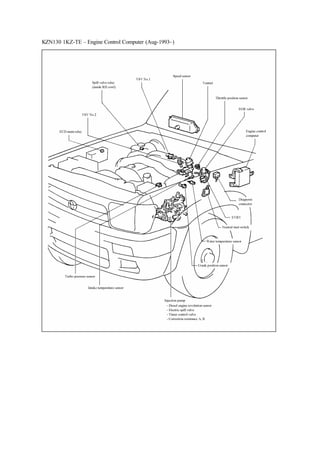
- 1. KZN130 1KZ-TE – Engine Control Computer (Aug-1993~)
- 2. KZN130 1KZ-TE - Engine Control Diagnosis Trouble Codes List Code No Diagnosis Item Diagnosis Contents 1. Diagnosis condition 2. Abnormal condition 3. Abnormal term Probable Inspection Area 12 Revolution Signal 1 [TDC+, TDC-] 1. Engine revolution is more than 400rpm 2. No crank position signal (TDC signal) input • Wiring and connector (crank position sensor) • Engine control computer 1. Engine revolution is more than 680rpm, STA is OFF 2. No NE signal input 3. More than 0.5 seconds 13 Revolution Signal 2 [NE+, NE-] 1. For 2 seconds after STA ON signal is input 2. No NE signal input • Wiring and connector (diesel engine revolution sensor) • Engine control computer 14 Timer Control Valve [TCV] 1. Coolant temperature is 45°C or more, +B is 11V or more, while injection timing feedback is activated, STA is OFF 2. Timing is differ from target approx.7° (crank angle). 3. More than 5 seconds • Wiring and connector • Fuel filter (choked) • Fuel (frozen, air-in) • Injection pump (internal pressure) • Engine control computer 16 ECT CPU 2. ECT CPU malfunction • Engine control computer 22 Water Temperature Sensor [THW, E2] 2. Open or short in water temperature senor circuit 3. More than 0.5 seconds • Wiring and connector (water temperature sensor circuit) • Water temperature senor • Engine control computer 24 Intake Temperature Sensor [THA, E2] 2. Open or short in intake temperature sensor circuit 3. More than 0.5 seconds • Wiring and connector (intake temperature sensor circuit) • Intake temperature sensor • Engine control computer 32 Correction Resistance [VRP, VRT, E2] 2. Open or short in correction resistance circuit 3. More than 0.5 seconds • Wiring and connector (correction resistance circuit) • Correction resistance • Engine control computer
- 3. 35 Turbo Pressure Sensor [PIM, VC, E2] 1. Engine revolution is 2400rpm or more, accelerator position is 52% or more 2. Intake pressure signal is abnormally low or high. 3. More than 2 seconds • Wiring and connector (turbo pressure sensor circuit) • Turbo pressure sensor • Gas filter (choked) • Turbo charger • Engine control computer 39 Fuel Temperature Sensor [THF, E2] 2. Open or short in fuel temperature sensor circuit • Wiring and connector (fuel temperature sensor circuit) • Fuel temperature sensor • Engine control computer 41 Throttle Position Sensor [IDL, VA, VC, E2] 2. Open or short in throttle position sensor circuit • Wiring and connector (throttle position sensor circuit) • Engine control computer 42 Speed Sensor [SP1] 1. M/T: engine revolution is 2400rpm or more and less than 4000rpm, accelerator position is 52% or more, coolant temperature is 60° or more. A/T: engine revolution is 2800rpm or more, shift position is other than P, N range. 2. Vehicle speed signal is 0km/h 3. More than 8 seconds • Wiring and connector (speed sensor circuit) • Speed sensor • Engine control computer 43 Starter Signal [STA] 1. Engine revolution is 1200rpm or more 2. Starter signal 3. More than 10 seconds • Wiring and connector • Engine control computer 51 Switch Signal [A/C, IDL, NSW] 1. Connected TE1 and E1 of the diagnosis connector, A/C ON or IDL contact OFF and STA OFF (for A/T, shift position is other than P, N range) • Wiring and connector (A/C switch, throttle position sensor IDL circuit, neutral start switch) • Throttle position sensor • Engine control computer
- 4. KZN130 1KZ-TE - Engine Control Computer Terminal Configuration Terminal No. Terminal Name Terminal No. Terminal Name Terminal No. Terminal Name Terminal No. Terminal Name A-1 +BF B-1 THF C-1 EGR C-17 NE- A-2 BATT B-2 PIM C-2 STA C-18 TDC- A-3 +BG B-3 THA C-3 H-IND C-19 A-4 ACT B-4 THW C-4 NE+ C-20 A-5 B-5 C-5 TDC+ C-21 A-6 G-IND B-6 VRP C-6 C-22 A-7 +B B-7 TE1 C-7 SVR C-23 FSW A-8 W B-8 VF C-8 M-REL C-24 E1 A-9 IGSW B-9 E2 C-9 S/TH2 C-25 A-10 A/C B-10 VA C-10 S/TH1 C-26 E02 A-11 SP1 B-11 VC C-11 SPV A-12 TAC B-12 IDL C-12 TCV B-13 C-13 E01 B-14 VRT C-14 S-REL B-15 TE2 C-15 B-16 C-16 HSW
- 5. KZN130 Manual Transmission Inspection Item Terminal Inspection Condition Standard (V) BATT – E1 Always 9~14 +B – E1 +BF – E1 +BG – E1 IGSW – E1 Engine is stopped, IG ON 9~14Power VC – E1 Engine is stopped, IG ON 4.5~5.5 ECD Main Relay M-REL – E1 Engine is stopped, IG ON 9~14 Spill Valve Relay SVR – E1 Engine is stopped, IG ON 0~1.5 Atmosphere pressure (760mmHg) 1.3~1.9 When apply negative pressure of 300mmHg (460mmHg) 0.2~0.9 Turbo Pressure Sensor PIM – E1 When apply pressure of 1kg/cm2 4.0~4.6 Close throttle valve fully 0.1~0.8 VA– E1 Open throttle valve fully 3.2~4.9 Close throttle valve fully 0~3 Throttle Position Sensor IDL – E1 Open throttle valve fully 9~14 Intake Temperature Sensor THA – E1 Intake temperature is 0~80°C (after warmed up engine) 0.5~3.4 Water Temperature Sensor THW – E1 Coolant temperature is 60~120°C (after warmed up engine) 0.1~0.8 Crank Position Sensor TDC+ - TDC- While idling Generation pulse occurs Speed Sensor SP1 – E1 While driving vehicle at approx.20km/h Generation pulse occurs Revolution Signal NE+ - NE- While idling Generation pulse occurs Starter Signal STA – E1 While cranking 6 or more Engine is stopped, IG ON 9~14 Electric Spill Valve SPV – E1 While idling Generation pulse occurs Engine is stopped, IG ON 9~14 Timer Control Valve TCV – E1 While idling Generation pulse occurs
- 6. VRP – E1 Engine is stopped, IG ON 0.2~4.5Correction Resistance VRT – E1 Engine is stopped, IG ON 0~5 While idling 9~14 EGR Control EGR – E1 After warmed up engine, maintain engine revolution at 1500rpm and hold it 0~3 Engine is stopped, IG ON 9~14 VSV No.1 S/TH1 – E1 Turn IG from ON to OFF 0~3 for 2 seconds Coolant temperature is less than 75°C, while idling 9~14 VSV No.2 S/TH2 – E1 Turn IG from ON to OFF 0~3 for 2 seconds Fuel Temperature Sensor THF – E1 IG ON (when cold start) 0.5~3.4 Turn IG from OFF to ON 9~14 Glow Plug Relay S-REL – E1 While idling (after after-glow is completed) 0~1.5 Turn IG from OFF to ON 0~3Glow Indicator Lamp G-IND – E1 While idling 9~14 When check engine warning lam is ON (disconnect connector from water temperature sensor) 0~3 Check Engine Lamp W – E1 While idling (when warning lam is OFF) 9~14 Tachometer Output TAC – E1 While idling Generation pulse occurs A/C ON (magnet clutch ON) 0~1.5 A/C – E1 A/C OFF 7.5~14 A/C ON (magnet clutch ON) 9~14 A/C Signal ACT – E1 A/C OFF 0~3 Engine is stopped, IG ON 9~14 Others TE1, TE2 – E1 Connected TE1 and E1, TE2 and E1 of the diagnosis connector 0~3
- 7. Connected TE1 and E1 of the diagnosis connector (when there is no diagnosis trouble code memorised) 4.3~5.7 VF – E1 Disconnect connector from water temperature senor, and connect TE1 and E1 of the diagnosis connector (when diagnosis trouble code output) 0~1 H-IND – E1 When heater indicator lamp is ON 0~3 When depressed heater idle up switch 0~3 HSW – E1 When released heater idle up switch 9~14 Others E1, E2, E01, E02 – body earth (inspection of continuity) (always continuity)
- 8. Terminal No Terminal Name Terminal No Terminal Name Terminal No Terminal Name Terminal No Terminal Name Terminal No Terminal Name A-1 BATT A-17 OIL-W B-1 VC C-1 SL C-17 NE- A-2 +BG A-18 TAC B-2 PIM C-2 S1 C-18 TDC- A-3 M-REL A-19 ATC B-3 THA C-3 C-19 SP2 A-4 STP A-20 DG B-4 THW C-4 NE+ C-20 L A-5 W A-21 OD1 B-5 THF C-5 TDC+ C-21 2 A-6 A-22 NSW B-6 VRP C-6 C-22 N A-7 G-IND B-7 VRT C-7 SVR C-23 L4 A-8 H-IND B-8 VF C-8 HSW C-24 EGR A-9 SP1 B-9 E2 C-9 S/TH2 C-25 S-REL A-10 A/C B-10 TFN C-10 S/TH1 C-26 E02 A-11 STA B-11 VA C-11 SPV A-12 +B B-12 IDL C-12 TCV A-13 +BF B-13 THO C-13 E01 A-14 IGSW B-14 TE2 C-14 E1 A-15 P B-15 TE1 C-15 S2 A-16 OD2 B-16 C-16
- 9. KZN130 Automatic Transmission Inspection Item Terminal Inspection Condition Standard (V) BATT – E1 Always 9~14 +B – E1 +BF – E1 +BG – E1 IGSW – E1 Engine is stopped, IG ON 9~14Power VC – E1 Engine is stopped, IG ON 4.5~5.5 ECD Main Relay M-REL – E1 Engine is stopped, IG ON 9~14 Spill Valve Relay SVR – E1 Engine is stopped, IG ON 0~1.5 Atmosphere pressure (760mmHg) 1.3~1.9 When apply negative pressure of 300mmHg (460mmHg) 0.2~0.9 Turbo Pressure Sensor PIM – E1 When apply pressure of 1kg/cm2 4.0~4.6 Close throttle valve fully 0.1~0.8 VA– E1 Open throttle valve fully 3.2~4.9 Close throttle valve fully 0~3 Throttle Position Sensor IDL – E1 Open throttle valve fully 9~14 Intake Temperature Sensor THA – E1 Intake temperature is 0~80°C (after warmed up engine) 0.5~3.4 Water Temperature Sensor THW – E1 Coolant temperature is 60~120°C (after warmed up engine) 0.1~0.8 Crank Position Sensor TDC+ - TDC- While idling Generation pulse occurs SP1 – E1 While driving vehicle at approx.20km/h Generation pulse occurs Speed Sensor SP2 – E1 Rotate drive wheel slowly Generation pulse occurs Revolution Signal NE+ - NE- While idling Generation pulse occurs Starter Signal STA – E1 While cranking 6 or more Engine is stopped, IG ON 9~14 Electric Spill Valve SPV – E1 While idling Generation pulse occurs
- 10. Engine is stopped, IG ON 9~14 Timer Control Valve TCV – E1 While idling Generation pulse occurs VRP – E1 Engine is stopped, IG ON 0.2~4.5Correction Resistance VRT – E1 Engine is stopped, IG ON 0~5 While idling 9~14 EGR Control EGR – E1 After warmed up engine, maintain engine revolution at 1500rpm and hold it 0~3 Engine is stopped, IG ON 9~14 VSV No.1 S/TH1 – E1 Turn IG from ON to OFF 0~3 for 2 seconds Coolant temperature is 75°C, while idling 9~14 VSV No.2 S/TH2 – E1 Turn IG from ON to OFF 0~3 for 2 seconds Turn IG from OFF to ON 9~14 Glow Plug Relay S-REL – E1 While idling (after after-glow is completed) 0~1.5 Turn IG from OFF to ON 0~3Glow Indicator Lamp G-IND – E1 While idling 9~14 When check engine warning lamp is ON (disconnect connector from water temperature sensor) 0~3 Check Engine Lamp W – E1 While idling (when warning lamp is OFF) 9~14 Shift lever is P, N range 0~3Neutral Start Switch NSW – E1 Shift lever is other than P, N range 9~14 Tachometer Output TAC – E1 While idling Generation pulse occurs A/C ON (magnet clutch ON) 0~1.5 AC – E1 A/C OFF 7.5~14 A/C ON (magnet clutch ON) 9~14 A/C Signal ACT – E1 A/C OFF 0~3
- 11. Fuel Temperature Sensor THF – E1 IG ON (when cold start) 0.5~3.4 Engine is stopped, IG ON 9~14 TE1, TE2 – E1 Connected TE1 and E1, TE2 and E1 of the diagnosis connector 0~3 Connected TE1 and E1 of the diagnosis connector (when there is no diagnosis trouble code memorised) 4.3~5.7 VF – E1 Disconnect connector from water temperature sensor, connected TE1 and E1 of the diagnosis connector (when diagnosis trouble codes output) 0~1 H-IND – E1 When heater indicator lamp is ON 0~3 When depressed heater idle up switch 0~3 HSW – E1 When released heater idle up switch 9~14 Others E1, E2, E01, E02 – body earth (inspection of continuity) (always continuity)