Mxd Snapping
•
0 gostou•677 visualizações

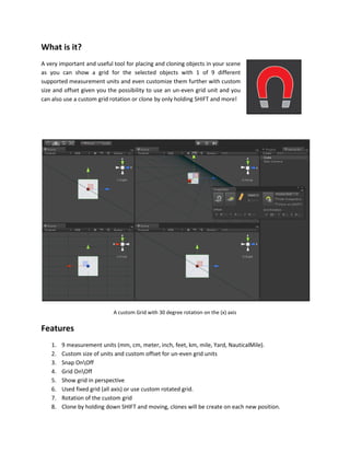
A very important and useful tool for placing, snapping and cloning objects in your scene! you can use fixed or rotated grid with alot of options to make your objects aligned easily.
Denunciar
Compartilhar
Denunciar
Compartilhar
Baixar para ler offline

Recomendados
MXD Edit
This document summarizes MXD Edit, a Unity asset that allows for small modifications to imported or existing 3D models directly within Unity. Key features include translating, rotating, and scaling vertices, edges, triangles, and faces. It also enables extruding faces and deleting polygons. While not intended as a full 3D modeling program, MXD Edit makes minor geometry edits fast and supports collision updates and multi-selection. Performance is prioritized for large meshes over complex editing tools.
Rhino to Ecotect
This document provides a 20-step process for transferring an architectural model created in Rhino into Ecotect for lighting analysis. It begins with preparing the Rhino model by ensuring clean geometry organized by layers that specify materials. The model is then exported as a DXF file and imported into a new Ecotect scheme. Zones are created for each Rhino layer and materials are assigned. Once complete, the model is ready for lighting analysis in Ecotect.
Laser Cutting: Advanced Joinery
This document provides instructions for creating different types of laser cut joinery, including waffle structure joinery, unrolled tabbed joinery, and notched joinery. The waffle structure joinery instructions involve creating contours on a surface in Rhino to divide it into sections, then extruding and splitting the surfaces to create interlocking pieces. The unrolled tabbed joinery instructions describe unfolding a 3D shape, adding score and cut lines, and using offsets to create tabs for assembly. The notched joinery instructions demonstrate dividing and offsetting edges to create notches, then trimming and projecting the pieces for cutting. Consideration is given to accounting for kerf width for a proper press fit.
Roland Primer 3D Scanner
The document provides an overview of the Roland 3D laser scanner. It describes the key components of the scanner like the door, table, and power button. It explains how to properly mount objects for scanning and notes they should not be too large, transparent, or glossy. The document outlines the software setup and scanning process, noting the importance of centering objects and using the correct pitches to control resolution for plane and rotary scans. It emphasizes safety, such as keeping the door closed while scanning to avoid cancelling the process.
Introduction to Rhino
This document provides a summary of key tools and concepts in Rhino. It discusses how Rhino uses NURBS to create smooth complex surfaces defined by a few control points. It outlines the basic modeling interface with four views, tool palette, and controls. It explains how to set up grids and units and use various snapping, locking and projection tools for accurate modeling. Finally, it summarizes the main modeling tools for points, curves, surfaces, solids, object manipulation and surface creation techniques like lofting and extruding.
Robot Studio
1) The document provides step-by-step instructions for creating a robotic station in RobotStudio, including importing custom geometry, setting up the user geometry and library folders, moving imported geometry, creating a custom tool, and attaching the tool to a robotic arm.
2) Key steps include launching RobotStudio, creating a new station with a robot controller and model, importing SAT files from Rhino as custom geometry, and using functions like rotate, place one point, and set position to move the imported geometry.
3) The document also details how to create a frame at the tip of the imported tool geometry, use the tool wizard to define the tool properties and TCP, and save the tool as a library file
Rolling The Dice
This tutorial shows how to create a dice roll animation in 3ds Max using the reactor plugin. It is divided into two parts:
1) Creating a 3D dice model with inset and extrude modifiers to add dots. Materials are added to color the dots.
2) Adding the dice and floor objects to a reactor rigid body collection to simulate physics as the dice are thrown and bounce on the floor surface. The reactor animation can then be rendered.
Fusion 360 Tutorial
Fusion 360 is free 3D modeling software that students can use. It can import files from other 3D modeling programs like Rhino. This document provides steps to import a Rhino file into Fusion 360, make adjustments to the model like moving and resizing it, then set up toolpaths to CNC mill the model using Autodesk's CAM module. It describes how to select the tool, depths, stepover distances and other settings, then simulate and post-process the toolpath into G-code that can be run on a CNC machine like the Carvey.
Adobe Illustrator CC 2018
This document provides an overview of key features and functions in Adobe Illustrator CC 2018 for creating vector graphics. It discusses how to set up files and workspaces, use tools like layers, strokes, and transforms, and complete tasks such as blending, perspective drawing, effects, and saving in different file formats like PDF. The document is intended as a tutorial or guide for using Illustrator's vector graphics capabilities.
Electric Lighting Ecotect
The document provides a 10 step process for modeling electric lighting in Ecotect:
1. Create a room zone and place a light at the ceiling height.
2. Array the lights along the room and mirror them to both sides.
3. Assign light materials from premade options or custom materials.
4. Generate an analysis grid and perform a lighting level calculation over the grid.
5. View the electric light levels analysis and export the scene file.
Google sketchup8
Google SketchUp is 3D modeling software that allows users to create models of anything they can imagine. Models can be built from scratch or downloaded from the Google 3D Warehouse, a large online repository of user-created models. Basic tools include navigation tools to orbit, zoom, and pan around models as well as drawing tools to create shapes. More advanced tools allow pushing and pulling faces, moving objects, and erasing edges. Components and groups allow isolating parts of models. Textures can be optimized and applied to surfaces to add realism. Models can be accurately positioned using Google Earth and exported in formats like CityGML for GIS applications.
Autocad Prsentation
It is introductory ppt for AutoCAD and its capabilities with Proposed learning goal. Made to self teach.
video links are provided for easy clarification.
click underlined lines
Finite Element Simulation with Ansys Workbench 14
The document provides step-by-step instructions for creating a 3D solid model of a W16x50 steel beam in ANSYS Workbench. It describes sketching the cross-section profile on the xy-plane, adding symmetry and dimensional constraints, and then extruding the sketch to generate the full 3D beam geometry 10 feet in length. Additional techniques demonstrated include copying/pasting sketches, trimming excess lines, adding fillets, and moving dimensional values. The overall purpose is to practice basic sketching skills needed for geometry creation in simulations.
Drawing Splines on 3D
This document provides instructions for using a Java application for drawing splines in 3D. It describes how to launch the application, the toolbar functions for navigation, drawing, modifying, and saving curves. Key classes are outlined including those for handling user input, managing the scene graph, and the spline subclasses. The behaviors for picking, drawing, joining, and cutting curves are also summarized.
Tutorial20
This document provides instructions for using ArcScene to view and navigate 3D data, draping shapefiles over terrain, extruding shapefiles to create 3D buildings, creating animations in ArcScene, and exporting ArcScene projects and shapefiles to Google Earth. It describes how to open ArcScene, add data, navigate the 3D environment, drape and extrude shapefiles, create and export animations, and export shapefiles as KML for viewing in Google Earth.
Ultimaker 2+
The document provides information about the Ultimaker 2+ 3D printer, including descriptions of its main parts, how to prepare and export files for printing, loading and changing filament, troubleshooting clogs, and ensuring successful prints. It details the slicing and printing process, from importing models to calibrating the first layer and monitoring a print's progress. Removal of completed prints is also addressed.
Cdi pd fusion 360 hyperloop
1) The document provides step-by-step instructions for creating a 3D model of a hyperloop train and track using Fusion 360. It describes how to sculpt and model the hyperloop body, rear section, and a small section of track.
2) It then explains how to add appearances and materials to the different components, assemble them together using joints, position and render the final assembly.
3) The overall purpose is to provide guidance to innovatively design a hyperloop train and surrounding infrastructure as a learning project in Fusion 360.
MakerBot Replicator 2x Primer
The document provides instructions for using a Makerbot Replicator 2X 3D printer. It describes how to level the build plate, load and unload filament, use the Makerware software to prepare files for printing including orientation, scaling and dual extrusion. It also provides tips for prepping the build surface with ABS slurry, removing prints, installing new Kapton tape, and using an acetone vapor bath to smooth prints.
Workbench tutorial airfoil
This tutorial provides instructions for creating a fluid volume and mesh around a NACA 4314 airfoil and analyzing the flow in FLUENT. It describes how to generate data points defining the airfoil geometry, import these into DesignModeler to create the airfoil solid body, then use DesignModeler operations to subtract the airfoil from a larger fluid volume and slice the remaining volume. Instructions are given to label faces, insert edge sizing controls, and generate a mesh in Meshing before launching FLUENT for analysis.
Motion tween resize
Motion tweening allows objects in Flash to move from one position to another over time. It creates intermediate frames between keyframes to smoothly transition movement or other property changes. The document outlines the steps to create a basic motion tween: import an image, convert it to a symbol, insert keyframes on frames 1 and 20, move the symbol to different positions on each keyframe, and Flash will generate the in-between animation.
Using Solid Tools in NX 8.5
Swoosh Technologie's Application Engineer, Brian Brown walks you through the steps of using solid tools in Siemens PLM's NX CAM 8.5.
Catia Part04
The document discusses various advanced dress-up features in SolidWorks including fillets, chamfers, draft angles, shells, and thickness. It provides instructions on how to apply each feature, highlights important parameters to adjust, and includes screenshots of parts that have been modified with each feature. Key features covered are fillets to round edges, chamfers to bevel edges at an angle, adding draft angles to parts for easier mold removal, shelling to hollow out a solid part, and increasing thickness on selected faces.
NX_CAD
The document provides an overview of the NX7.5 basic training course, including how to get started with NX7.5, create and save part files, use the modeling interface, select and manipulate objects, create sketches, apply geometric and dimensional constraints, and perform basic extrude and revolve swept features. It describes the key interface elements and commands for navigating the software and constructing 3D models.
How to create a Composite FEM via Hypermesh
You will learn how to develop a composite part in Hypermesh. Specifically, how to assign an orthotropic material properties and a material direction; define a normal direction, and view the laminate’s material and ply orientations.
Catia Part06
REFERENCE ELEMENTS such as planes allow for more flexibility when modeling parts compared to only working on outer surfaces. To cut a step into the middle of an edge, a reference plane must first be added and a sketch created on that plane before pocketing out the shape. This provides more control over feature placement than relying solely on part faces. The document then demonstrates using a reference plane to cut a step into the middle of the front edge by sketching on the plane and pocketing.
PIVOT ANIMATOR - USER GUIDE - VIDEO EDITING AND MAKING SOFTWARE
Pivot Animator is a simple stick figure animation program. It allows users to create animations by positioning figures frame-by-frame and adding the frames to a timeline. Key features include tools for adding, editing, and positioning stick figure types, as well as exporting the finished animation in common video formats.
Solve An Inequality Graphically
To solve an inequality graphically using a graphing calculator:
1) Graph the functions involved in the inequality on the same screen and find their intercept points.
2) Record the x-interval values where one function is above the other based on the graph.
3) Check the solution by re-graphing the inequality and using trace to verify the intervals where the plotted inequality function is above 1.
Catia Part07
The document provides instructions for assembling parts in Catia assembly design mode. It describes how to bring individual parts into the assembly environment from their saved locations, then use coincidence and contact constraints to connect the parts in their desired positions and orientations relative to each other. It demonstrates this by inserting a plate with a hole and rod part into an assembly, then using a coincidence constraint on their centerlines and an offset constraint to connect them so half the rod sticks out on each side of the plate.
Google sketchup8
Google SketchUp is 3D modeling software that allows users to create models of anything they can imagine. Models can be built from scratch or downloaded from the Google 3D Warehouse, a large online repository of user-created models. Basic tools include navigation tools to orbit, zoom, and pan around models as well as drawing tools to create shapes. More advanced tools allow pushing and pulling faces, moving objects, and erasing edges. Components and groups allow isolating parts of models. Models can be optimized and textures applied for use in Google Earth. The software's positioning and CityGML plug-in tools aid in accurately placing models in real-world locations.
Sketchup basic course by Eng. Khalid A. Mter
This document provides an overview and learning objectives for a course on building 3D models in Google SketchUp. It will teach students how to use SketchUp's tools to create and modify 2D and 3D geometry, including the line, circle, rectangle, arc, and polygon tools. It will also cover more advanced tools like push/pull to add volume, follow me to create paths, and array/rotate tools to duplicate objects. The document includes step-by-step examples of creating a simple doghouse model and modifying geometry. Upon completing the course, students will be able to proficiently use SketchUp's modeling tools.
Mais conteúdo relacionado
Mais procurados
Adobe Illustrator CC 2018
This document provides an overview of key features and functions in Adobe Illustrator CC 2018 for creating vector graphics. It discusses how to set up files and workspaces, use tools like layers, strokes, and transforms, and complete tasks such as blending, perspective drawing, effects, and saving in different file formats like PDF. The document is intended as a tutorial or guide for using Illustrator's vector graphics capabilities.
Electric Lighting Ecotect
The document provides a 10 step process for modeling electric lighting in Ecotect:
1. Create a room zone and place a light at the ceiling height.
2. Array the lights along the room and mirror them to both sides.
3. Assign light materials from premade options or custom materials.
4. Generate an analysis grid and perform a lighting level calculation over the grid.
5. View the electric light levels analysis and export the scene file.
Google sketchup8
Google SketchUp is 3D modeling software that allows users to create models of anything they can imagine. Models can be built from scratch or downloaded from the Google 3D Warehouse, a large online repository of user-created models. Basic tools include navigation tools to orbit, zoom, and pan around models as well as drawing tools to create shapes. More advanced tools allow pushing and pulling faces, moving objects, and erasing edges. Components and groups allow isolating parts of models. Textures can be optimized and applied to surfaces to add realism. Models can be accurately positioned using Google Earth and exported in formats like CityGML for GIS applications.
Autocad Prsentation
It is introductory ppt for AutoCAD and its capabilities with Proposed learning goal. Made to self teach.
video links are provided for easy clarification.
click underlined lines
Finite Element Simulation with Ansys Workbench 14
The document provides step-by-step instructions for creating a 3D solid model of a W16x50 steel beam in ANSYS Workbench. It describes sketching the cross-section profile on the xy-plane, adding symmetry and dimensional constraints, and then extruding the sketch to generate the full 3D beam geometry 10 feet in length. Additional techniques demonstrated include copying/pasting sketches, trimming excess lines, adding fillets, and moving dimensional values. The overall purpose is to practice basic sketching skills needed for geometry creation in simulations.
Drawing Splines on 3D
This document provides instructions for using a Java application for drawing splines in 3D. It describes how to launch the application, the toolbar functions for navigation, drawing, modifying, and saving curves. Key classes are outlined including those for handling user input, managing the scene graph, and the spline subclasses. The behaviors for picking, drawing, joining, and cutting curves are also summarized.
Tutorial20
This document provides instructions for using ArcScene to view and navigate 3D data, draping shapefiles over terrain, extruding shapefiles to create 3D buildings, creating animations in ArcScene, and exporting ArcScene projects and shapefiles to Google Earth. It describes how to open ArcScene, add data, navigate the 3D environment, drape and extrude shapefiles, create and export animations, and export shapefiles as KML for viewing in Google Earth.
Ultimaker 2+
The document provides information about the Ultimaker 2+ 3D printer, including descriptions of its main parts, how to prepare and export files for printing, loading and changing filament, troubleshooting clogs, and ensuring successful prints. It details the slicing and printing process, from importing models to calibrating the first layer and monitoring a print's progress. Removal of completed prints is also addressed.
Cdi pd fusion 360 hyperloop
1) The document provides step-by-step instructions for creating a 3D model of a hyperloop train and track using Fusion 360. It describes how to sculpt and model the hyperloop body, rear section, and a small section of track.
2) It then explains how to add appearances and materials to the different components, assemble them together using joints, position and render the final assembly.
3) The overall purpose is to provide guidance to innovatively design a hyperloop train and surrounding infrastructure as a learning project in Fusion 360.
MakerBot Replicator 2x Primer
The document provides instructions for using a Makerbot Replicator 2X 3D printer. It describes how to level the build plate, load and unload filament, use the Makerware software to prepare files for printing including orientation, scaling and dual extrusion. It also provides tips for prepping the build surface with ABS slurry, removing prints, installing new Kapton tape, and using an acetone vapor bath to smooth prints.
Workbench tutorial airfoil
This tutorial provides instructions for creating a fluid volume and mesh around a NACA 4314 airfoil and analyzing the flow in FLUENT. It describes how to generate data points defining the airfoil geometry, import these into DesignModeler to create the airfoil solid body, then use DesignModeler operations to subtract the airfoil from a larger fluid volume and slice the remaining volume. Instructions are given to label faces, insert edge sizing controls, and generate a mesh in Meshing before launching FLUENT for analysis.
Motion tween resize
Motion tweening allows objects in Flash to move from one position to another over time. It creates intermediate frames between keyframes to smoothly transition movement or other property changes. The document outlines the steps to create a basic motion tween: import an image, convert it to a symbol, insert keyframes on frames 1 and 20, move the symbol to different positions on each keyframe, and Flash will generate the in-between animation.
Using Solid Tools in NX 8.5
Swoosh Technologie's Application Engineer, Brian Brown walks you through the steps of using solid tools in Siemens PLM's NX CAM 8.5.
Catia Part04
The document discusses various advanced dress-up features in SolidWorks including fillets, chamfers, draft angles, shells, and thickness. It provides instructions on how to apply each feature, highlights important parameters to adjust, and includes screenshots of parts that have been modified with each feature. Key features covered are fillets to round edges, chamfers to bevel edges at an angle, adding draft angles to parts for easier mold removal, shelling to hollow out a solid part, and increasing thickness on selected faces.
NX_CAD
The document provides an overview of the NX7.5 basic training course, including how to get started with NX7.5, create and save part files, use the modeling interface, select and manipulate objects, create sketches, apply geometric and dimensional constraints, and perform basic extrude and revolve swept features. It describes the key interface elements and commands for navigating the software and constructing 3D models.
How to create a Composite FEM via Hypermesh
You will learn how to develop a composite part in Hypermesh. Specifically, how to assign an orthotropic material properties and a material direction; define a normal direction, and view the laminate’s material and ply orientations.
Catia Part06
REFERENCE ELEMENTS such as planes allow for more flexibility when modeling parts compared to only working on outer surfaces. To cut a step into the middle of an edge, a reference plane must first be added and a sketch created on that plane before pocketing out the shape. This provides more control over feature placement than relying solely on part faces. The document then demonstrates using a reference plane to cut a step into the middle of the front edge by sketching on the plane and pocketing.
PIVOT ANIMATOR - USER GUIDE - VIDEO EDITING AND MAKING SOFTWARE
Pivot Animator is a simple stick figure animation program. It allows users to create animations by positioning figures frame-by-frame and adding the frames to a timeline. Key features include tools for adding, editing, and positioning stick figure types, as well as exporting the finished animation in common video formats.
Solve An Inequality Graphically
To solve an inequality graphically using a graphing calculator:
1) Graph the functions involved in the inequality on the same screen and find their intercept points.
2) Record the x-interval values where one function is above the other based on the graph.
3) Check the solution by re-graphing the inequality and using trace to verify the intervals where the plotted inequality function is above 1.
Catia Part07
The document provides instructions for assembling parts in Catia assembly design mode. It describes how to bring individual parts into the assembly environment from their saved locations, then use coincidence and contact constraints to connect the parts in their desired positions and orientations relative to each other. It demonstrates this by inserting a plate with a hole and rod part into an assembly, then using a coincidence constraint on their centerlines and an offset constraint to connect them so half the rod sticks out on each side of the plate.
Mais procurados (20)
PIVOT ANIMATOR - USER GUIDE - VIDEO EDITING AND MAKING SOFTWARE
PIVOT ANIMATOR - USER GUIDE - VIDEO EDITING AND MAKING SOFTWARE
Semelhante a Mxd Snapping
Google sketchup8
Google SketchUp is 3D modeling software that allows users to create models of anything they can imagine. Models can be built from scratch or downloaded from the Google 3D Warehouse, a large online repository of user-created models. Basic tools include navigation tools to orbit, zoom, and pan around models as well as drawing tools to create shapes. More advanced tools allow pushing and pulling faces, moving objects, and erasing edges. Components and groups allow isolating parts of models. Models can be optimized and textures applied for use in Google Earth. The software's positioning and CityGML plug-in tools aid in accurately placing models in real-world locations.
Sketchup basic course by Eng. Khalid A. Mter
This document provides an overview and learning objectives for a course on building 3D models in Google SketchUp. It will teach students how to use SketchUp's tools to create and modify 2D and 3D geometry, including the line, circle, rectangle, arc, and polygon tools. It will also cover more advanced tools like push/pull to add volume, follow me to create paths, and array/rotate tools to duplicate objects. The document includes step-by-step examples of creating a simple doghouse model and modifying geometry. Upon completing the course, students will be able to proficiently use SketchUp's modeling tools.
Mode d’emploie delta force xtreme mission editor
The document provides instructions for using the Mission Editor tool to create missions for NovaLogic's games. It begins with an overview of navigating the tool using keyboard shortcuts, mouse commands, and screen buttons. It then outlines the basic steps for creating a new mission, including selecting a terrain, mission name, and player start marker. The document recommends saving work often and provides links to additional sections that detail more advanced editing functions like placing enemies and setting mission events.
Cinema 4D R20 ESSENTIALS
1. Fields can be used to form selections of objects, animate selections over time, and manipulate effects through effectors.
2. With polygons, the Set Selection tag allows applying fields to select parts of an object. Fields like Formula can select every other polygon.
3. In MoGraph, fields select parts of a matrix and effectors add motion. Effector fields then further manipulate the motion.
Poser presentation1
The document provides descriptions of various tools and controls in Poser's user interface. It covers the menu bar, light controls, camera controls, room tabs, editing tools, document window, display controls, properties and parameters palettes, and animation controls. Key points include that the menu bar provides access to Poser functionality, light controls adjust lighting properties, camera controls allow selecting and moving cameras, room tabs switch between rooms, and editing tools are used to pose 3D models. The document window is the viewport, display controls select preview modes, and properties and parameters palettes adjust object settings. Animation controls are also described.
Maya
This document provides a beginner's guide for animating a character in Autodesk Maya. It discusses building a character by creating a skeleton with joints, adding geometry, and binding them. It also covers adding controls like IK handles and flexors. The guide explains how to prepare the character for animation through techniques like expressions, constraints, and character nodes. It then discusses animating the character through keyframing, non-linear animation, and the Trax editor. Finally, it briefly touches on animating cameras, lighting, texturing, and rendering the scene.
ETECH_WEEK7-Image-Manipulation-Techniques-1.pdf
1. The document discusses various image editing techniques like cropping, blurring, adjustments, framing, and adding text overlays using the PicsArt application.
2. It provides step-by-step instructions for performing each technique, including selecting tools and adjusting settings.
3. The document also explains how to combine multiple images using layering and blending modes in PicsArt to design original composite images.
02 unity 3_d_part_1
Unity 3D is a game engine that allows users to create 3D games. The main components of a Unity project include scenes stored in the project view, game objects organized in the hierarchy, and views like the scene view to build levels and the game view to test games. Key concepts include parenting game objects to link their transformations and using the transform tools to move, rotate, and scale objects in the scene view.
Basics of 3D-Unity Tutorial.pptx
1) The document provides instructions on how to build a basic track in Unity using the MG-Karting modular track pieces. It covers how to move around the scene, add and manipulate objects, use progrids, and snap objects to the grid for precise placement.
2) Steps are given to place curved and straight track pieces, scale and rotate them, and connect them to form a basic oval track. The instructions recommend selecting, copying, and rotating pieces to efficiently duplicate sections of track.
3) By following the provided steps, the reader can create their first simple track layout in Unity. Precise transformations are aided by object snapping and progrids while basic navigation and manipulation tools are also overviewed.
3Dimention_lessonA_introMayaModeling.pptx
Maya is 3D art and animation software commonly used in film and games. It provides tools for modeling, texturing, rigging, animation, rendering, and visual effects. The interface includes menus, shelves, viewports, and panels to transform and edit 3D objects. Basic modeling techniques in Maya include using the polygon shelf to create objects, transforming objects using the move, rotate, and scale tools, and editing object components like vertices, edges, and faces.
OsiriX_new_guide_202204.pdf
This document provides a guide to using the medical imaging software OsiriX. It discusses how to open and view DICOM images, perform multi-planar reconstruction, volume rendering, image fusion, and other functions. Key points covered include how to customize windows and toolbars, use navigational shortcuts, perform measurements and create regions of interest, synchronize views, and adjust rendering settings such as shading and color lookup tables. The guide provides an overview of the software's main viewing and post-processing capabilities in 3 sentences or less.
Petrlel F 2 seismic display 2018 v1.1
This document provides instructions for displaying seismic data in Petrel in various windows, including Interpretation windows, 3D windows, and 2D windows. It describes how to open these windows, select seismic data to display, manipulate the data view, and set display options like scale, color, and annotations. Players that allow interactive panning through seismic sections in 3D and Interpretation windows are also introduced.
Petrel F 3 seismic intersections and data manipulation 2018 v1.1
The document discusses various techniques for visualizing and manipulating seismic data in Petrel, including:
- Inserting random lines and polyline intersections to create arbitrary seismic intersections
- Tiling windows and linking cameras between windows to synchronize views
- Using ghost curves to compare seismic signal patterns across faults
- Overlaying seismic attributes and vintages to aid interpretation
- Adjusting settings like transparency and annotation to control seismic data display
- Browsing and managing seismic surveys using the Survey manager tool.
Dwg 106 module 2 part 1
The document provides an overview of the SketchUp interface and basic tools. It describes the SketchUp screen layout, including the drawing and editing tools, drawing axes, and status/prompts area. It also explains the value control box. The document outlines the basic drawing tools like line, rectangle, polygon, arc, and circle. It covers viewing tools for orbiting, panning, zooming. It also summarizes manipulation tools for selecting, erasing, measuring, rotating, scaling, and offsetting objects. Finally, it discusses annotation tools for adding text and dimensions.
Autocad commands-1
This document provides an overview of common AutoCAD commands, including their keystrokes, icons, menus, and functions. It discusses commands for drawing basic shapes like lines and circles, modifying objects through commands like erase, copy, and move, and viewing and navigating drawings using zoom and pan tools. The document also outlines settings for object snaps and layers as well as commands for dimensions, text, and hatching.
Introduction to AutoCAD Commands
This document provides an overview of common AutoCAD commands, including their keystrokes, icons, menus, and functions. It discusses commands for drawing basic shapes like lines and circles, modifying objects through commands like erase, copy, and move, and viewing and navigating drawings using zoom and pan tools. The document also outlines settings for object snaps and layers as well as commands for dimensions, text, and hatching.
Std 11 Computer Chapter 2 Animation Tool: synfig (Part 2 Different Tools in ...
Std 11 Computer Chapter 2 Animation Tool: synfig (Part 2 Different Tools in Synfig) by Nuzhat Memon
AiM Spinner Design Tutorial in Solidworks
This tutorial will guide you through the steps to design a fidget spinner in Solidworks. We'll start by modeling a basic spinner, then we'll design our own counterweights to be machined. We'll make a dimensioned print for the counterweight, too! We'll end by creating an assembly for the spinner and I'll give you some next steps to take your design further.
Photoshop basics
This document provides an overview of basic photo editing in Adobe Photoshop CS 5.5. It describes the main interface elements like the menu bar, toolbar, work area, and palettes. It explains layers and how to organize images into layers that can be edited individually. Common tools are also outlined, including selection tools, alteration tools, and additional tools. Specific editing techniques like cropping and creating a photo collage are demonstrated through step-by-step activities. The document serves as an introduction for new Photoshop users to learn essential functions for image editing.
ERDAS_1.pdf
This document provides an introduction to using ERDAS Imagine software to display, analyze, and process raster images. It describes how to open and display Landsat images, use tools like the inquire cursor and histograms to examine pixel values, perform image enhancements like contrast stretching and NDVI, and make measurements on the images. Key steps covered include displaying images in false color, analyzing pixel values and histograms, creating spectral and spatial profiles, and generating an NDVI vegetation index from Landsat bands.
Semelhante a Mxd Snapping (20)
Petrel F 3 seismic intersections and data manipulation 2018 v1.1
Petrel F 3 seismic intersections and data manipulation 2018 v1.1
Std 11 Computer Chapter 2 Animation Tool: synfig (Part 2 Different Tools in ...
Std 11 Computer Chapter 2 Animation Tool: synfig (Part 2 Different Tools in ...
Último
Your One-Stop Shop for Python Success: Top 10 US Python Development Providers
Simplify your search for a reliable Python development partner! This list presents the top 10 trusted US providers offering comprehensive Python development services, ensuring your project's success from conception to completion.
Unlock the Future of Search with MongoDB Atlas_ Vector Search Unleashed.pdf
Discover how MongoDB Atlas and vector search technology can revolutionize your application's search capabilities. This comprehensive presentation covers:
* What is Vector Search?
* Importance and benefits of vector search
* Practical use cases across various industries
* Step-by-step implementation guide
* Live demos with code snippets
* Enhancing LLM capabilities with vector search
* Best practices and optimization strategies
Perfect for developers, AI enthusiasts, and tech leaders. Learn how to leverage MongoDB Atlas to deliver highly relevant, context-aware search results, transforming your data retrieval process. Stay ahead in tech innovation and maximize the potential of your applications.
#MongoDB #VectorSearch #AI #SemanticSearch #TechInnovation #DataScience #LLM #MachineLearning #SearchTechnology
Skybuffer SAM4U tool for SAP license adoption
Manage and optimize your license adoption and consumption with SAM4U, an SAP free customer software asset management tool.
SAM4U, an SAP complimentary software asset management tool for customers, delivers a detailed and well-structured overview of license inventory and usage with a user-friendly interface. We offer a hosted, cost-effective, and performance-optimized SAM4U setup in the Skybuffer Cloud environment. You retain ownership of the system and data, while we manage the ABAP 7.58 infrastructure, ensuring fixed Total Cost of Ownership (TCO) and exceptional services through the SAP Fiori interface.
“Building and Scaling AI Applications with the Nx AI Manager,” a Presentation...
“Building and Scaling AI Applications with the Nx AI Manager,” a Presentation...Edge AI and Vision Alliance
For the full video of this presentation, please visit: https://www.edge-ai-vision.com/2024/06/building-and-scaling-ai-applications-with-the-nx-ai-manager-a-presentation-from-network-optix/
Robin van Emden, Senior Director of Data Science at Network Optix, presents the “Building and Scaling AI Applications with the Nx AI Manager,” tutorial at the May 2024 Embedded Vision Summit.
In this presentation, van Emden covers the basics of scaling edge AI solutions using the Nx tool kit. He emphasizes the process of developing AI models and deploying them globally. He also showcases the conversion of AI models and the creation of effective edge AI pipelines, with a focus on pre-processing, model conversion, selecting the appropriate inference engine for the target hardware and post-processing.
van Emden shows how Nx can simplify the developer’s life and facilitate a rapid transition from concept to production-ready applications.He provides valuable insights into developing scalable and efficient edge AI solutions, with a strong focus on practical implementation.Digital Marketing Trends in 2024 | Guide for Staying Ahead
https://www.wask.co/ebooks/digital-marketing-trends-in-2024
Feeling lost in the digital marketing whirlwind of 2024? Technology is changing, consumer habits are evolving, and staying ahead of the curve feels like a never-ending pursuit. This e-book is your compass. Dive into actionable insights to handle the complexities of modern marketing. From hyper-personalization to the power of user-generated content, learn how to build long-term relationships with your audience and unlock the secrets to success in the ever-shifting digital landscape.
OpenID AuthZEN Interop Read Out - Authorization
During Identiverse 2024 and EIC 2024, members of the OpenID AuthZEN WG got together and demoed their authorization endpoints conforming to the AuthZEN API
How to Interpret Trends in the Kalyan Rajdhani Mix Chart.pdf
A Mix Chart displays historical data of numbers in a graphical or tabular form. The Kalyan Rajdhani Mix Chart specifically shows the results of a sequence of numbers over different periods.
5th LF Energy Power Grid Model Meet-up Slides
5th Power Grid Model Meet-up
It is with great pleasure that we extend to you an invitation to the 5th Power Grid Model Meet-up, scheduled for 6th June 2024. This event will adopt a hybrid format, allowing participants to join us either through an online Mircosoft Teams session or in person at TU/e located at Den Dolech 2, Eindhoven, Netherlands. The meet-up will be hosted by Eindhoven University of Technology (TU/e), a research university specializing in engineering science & technology.
Power Grid Model
The global energy transition is placing new and unprecedented demands on Distribution System Operators (DSOs). Alongside upgrades to grid capacity, processes such as digitization, capacity optimization, and congestion management are becoming vital for delivering reliable services.
Power Grid Model is an open source project from Linux Foundation Energy and provides a calculation engine that is increasingly essential for DSOs. It offers a standards-based foundation enabling real-time power systems analysis, simulations of electrical power grids, and sophisticated what-if analysis. In addition, it enables in-depth studies and analysis of the electrical power grid’s behavior and performance. This comprehensive model incorporates essential factors such as power generation capacity, electrical losses, voltage levels, power flows, and system stability.
Power Grid Model is currently being applied in a wide variety of use cases, including grid planning, expansion, reliability, and congestion studies. It can also help in analyzing the impact of renewable energy integration, assessing the effects of disturbances or faults, and developing strategies for grid control and optimization.
What to expect
For the upcoming meetup we are organizing, we have an exciting lineup of activities planned:
-Insightful presentations covering two practical applications of the Power Grid Model.
-An update on the latest advancements in Power Grid -Model technology during the first and second quarters of 2024.
-An interactive brainstorming session to discuss and propose new feature requests.
-An opportunity to connect with fellow Power Grid Model enthusiasts and users.
みなさんこんにちはこれ何文字まで入るの?40文字以下不可とか本当に意味わからないけどこれ限界文字数書いてないからマジでやばい文字数いけるんじゃないの?えこ...
ここ3000字までしか入らないけどタイトルの方がたくさん文字入ると思います。
Ocean lotus Threat actors project by John Sitima 2024 (1).pptx
Ocean Lotus cyber threat actors represent a sophisticated, persistent, and politically motivated group that poses a significant risk to organizations and individuals in the Southeast Asian region. Their continuous evolution and adaptability underscore the need for robust cybersecurity measures and international cooperation to identify and mitigate the threats posed by such advanced persistent threat groups.
Project Management Semester Long Project - Acuity
Acuity is an innovative learning app designed to transform the way you engage with knowledge. Powered by AI technology, Acuity takes complex topics and distills them into concise, interactive summaries that are easy to read & understand. Whether you're exploring the depths of quantum mechanics or seeking insight into historical events, Acuity provides the key information you need without the burden of lengthy texts.
Best 20 SEO Techniques To Improve Website Visibility In SERP
Boost your website's visibility with proven SEO techniques! Our latest blog dives into essential strategies to enhance your online presence, increase traffic, and rank higher on search engines. From keyword optimization to quality content creation, learn how to make your site stand out in the crowded digital landscape. Discover actionable tips and expert insights to elevate your SEO game.
Taking AI to the Next Level in Manufacturing.pdf
Read Taking AI to the Next Level in Manufacturing to gain insights on AI adoption in the manufacturing industry, such as:
1. How quickly AI is being implemented in manufacturing.
2. Which barriers stand in the way of AI adoption.
3. How data quality and governance form the backbone of AI.
4. Organizational processes and structures that may inhibit effective AI adoption.
6. Ideas and approaches to help build your organization's AI strategy.
Driving Business Innovation: Latest Generative AI Advancements & Success Story
Are you ready to revolutionize how you handle data? Join us for a webinar where we’ll bring you up to speed with the latest advancements in Generative AI technology and discover how leveraging FME with tools from giants like Google Gemini, Amazon, and Microsoft OpenAI can supercharge your workflow efficiency.
During the hour, we’ll take you through:
Guest Speaker Segment with Hannah Barrington: Dive into the world of dynamic real estate marketing with Hannah, the Marketing Manager at Workspace Group. Hear firsthand how their team generates engaging descriptions for thousands of office units by integrating diverse data sources—from PDF floorplans to web pages—using FME transformers, like OpenAIVisionConnector and AnthropicVisionConnector. This use case will show you how GenAI can streamline content creation for marketing across the board.
Ollama Use Case: Learn how Scenario Specialist Dmitri Bagh has utilized Ollama within FME to input data, create custom models, and enhance security protocols. This segment will include demos to illustrate the full capabilities of FME in AI-driven processes.
Custom AI Models: Discover how to leverage FME to build personalized AI models using your data. Whether it’s populating a model with local data for added security or integrating public AI tools, find out how FME facilitates a versatile and secure approach to AI.
We’ll wrap up with a live Q&A session where you can engage with our experts on your specific use cases, and learn more about optimizing your data workflows with AI.
This webinar is ideal for professionals seeking to harness the power of AI within their data management systems while ensuring high levels of customization and security. Whether you're a novice or an expert, gain actionable insights and strategies to elevate your data processes. Join us to see how FME and AI can revolutionize how you work with data!
Let's Integrate MuleSoft RPA, COMPOSER, APM with AWS IDP along with Slack
Discover the seamless integration of RPA (Robotic Process Automation), COMPOSER, and APM with AWS IDP enhanced with Slack notifications. Explore how these technologies converge to streamline workflows, optimize performance, and ensure secure access, all while leveraging the power of AWS IDP and real-time communication via Slack notifications.
20240609 QFM020 Irresponsible AI Reading List May 2024
Everything I found interesting about the irresponsible use of machine intelligence in May 2024
Último (20)
Your One-Stop Shop for Python Success: Top 10 US Python Development Providers
Your One-Stop Shop for Python Success: Top 10 US Python Development Providers
Unlock the Future of Search with MongoDB Atlas_ Vector Search Unleashed.pdf
Unlock the Future of Search with MongoDB Atlas_ Vector Search Unleashed.pdf
WeTestAthens: Postman's AI & Automation Techniques
WeTestAthens: Postman's AI & Automation Techniques
“Building and Scaling AI Applications with the Nx AI Manager,” a Presentation...
“Building and Scaling AI Applications with the Nx AI Manager,” a Presentation...
Digital Marketing Trends in 2024 | Guide for Staying Ahead
Digital Marketing Trends in 2024 | Guide for Staying Ahead
How to Interpret Trends in the Kalyan Rajdhani Mix Chart.pdf
How to Interpret Trends in the Kalyan Rajdhani Mix Chart.pdf
みなさんこんにちはこれ何文字まで入るの?40文字以下不可とか本当に意味わからないけどこれ限界文字数書いてないからマジでやばい文字数いけるんじゃないの?えこ...
みなさんこんにちはこれ何文字まで入るの?40文字以下不可とか本当に意味わからないけどこれ限界文字数書いてないからマジでやばい文字数いけるんじゃないの?えこ...
Ocean lotus Threat actors project by John Sitima 2024 (1).pptx
Ocean lotus Threat actors project by John Sitima 2024 (1).pptx
Best 20 SEO Techniques To Improve Website Visibility In SERP
Best 20 SEO Techniques To Improve Website Visibility In SERP
Driving Business Innovation: Latest Generative AI Advancements & Success Story
Driving Business Innovation: Latest Generative AI Advancements & Success Story
Let's Integrate MuleSoft RPA, COMPOSER, APM with AWS IDP along with Slack
Let's Integrate MuleSoft RPA, COMPOSER, APM with AWS IDP along with Slack
Deep Dive: AI-Powered Marketing to Get More Leads and Customers with HyperGro...
Deep Dive: AI-Powered Marketing to Get More Leads and Customers with HyperGro...
20240609 QFM020 Irresponsible AI Reading List May 2024
20240609 QFM020 Irresponsible AI Reading List May 2024
Mxd Snapping
- 1. What is it? A very important and useful tool for placing and cloning objects in your scene as you can show a grid for the selected objects with 1 of 9 different supported measurement units and even customize them further with custom size and offset given you the possibility to use an un-even grid unit and you can also use a custom grid rotation or clone by only holding SHIFT and more! A custom Grid with 30 degree rotation on the (x) axis Features 1. 9 measurement units (mm, cm, meter, inch, feet, km, mile, Yard, NauticalMile). 2. Custom size of units and custom offset for un-even grid units 3. Snap OnOff 4. Grid OnOff 5. Show grid in perspective 6. Used fixed grid (all axis) or use custom rotated grid. 7. Rotation of the custom grid 8. Clone by holding down SHIFT and moving, clones will be create on each new position.
- 2. Using MXD Snapping To open MXD Snapping window go to the main menu and click on Window->MXD->Snap menu item. Once you click on it a new window titled "SnapEditor" will appear: I you don't have any game object selected from the scene then the grid will not be shown as the grid is always relative to the center of the current selection. The following are the available options Icon Function Name Description Snap Off When the snap button holds this image then currently snapping is ON and if you want to deactivate snapping then click on it. Snap On When the snap button holds this image then currently snapping is OFF and if you want to activate snapping then click on it. Hide Grid When the showhide grid button holds this image then currently the grid is visible, click on the button to hide the grid. Show Grid When the showhide grid button holds this image then currently the grid is invisible, click on the button to show the grid.
- 3. Measurements Next to this image you will find the different measurement options, which are the following: 1. Unit: a. Millimeter(mm) b. Centimeter(cm) c. Meter d. Inch e. Feet f. kilometer(km) g. Mile h. Yard i. Nautical Mile 2. Size: You can multiple the unit by setting the size value, for example setting the size = 2 when the unit is (cm) means that the unit measured will be 2 cm. 3. Offset: Great if you want to have un-even grid units with specific size for every axis by setting the x,y,z values. Sample un-even grid: Snap Selected You click on this button to snap selected objects when snapping is toggled OFF. Hide Perspective Hide Perspective This option will hideshow the grid in the perspective view Clone on (SHIFT) Cloning Objects When toggled ON you can hold the SHIFT key to automatically clone your selected objects whenever you move them while snapping is enabled. Grid Type Grid Type You Can selected from 2 types of grids 1. Fixed Grid: The fixed grid will show axis-aligned grids depending on the sceneview so if you have 4 scene views with different directions then you will get different grids aligned depending on the sceneview, this will map to (X,Y,Z) 2. Custom Grid: The custom grid can be rotated using a rotation field and with it you can align objects to non axis-aligned locations.