
Recomendados
Recomendados
Mais conteúdo relacionado
Mais procurados
Mais procurados (20)
Semelhante a Chapter 1
Semelhante a Chapter 1 (20)
Último
Último (20)
Chapter 1
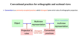
- 1. Conventional practices for orthographic and sectional views Convention is a commonly accepted practices which disregard some strict rules of orthographic projection.
- 2. PURPOSES To improve the clarity of a drawing. To facilitate the dimensioning. To reduce the drafting effort. To save or efficiently use a drawing space. CONVENTION PRACTICE FOR ORTHOGRAPHIC VIEWS 1. Incompleted views • Incompleted side view • Partial view • Half view • Local view Incompleted side views are side views that are eliminated a feature that can not clearly seen from a selected viewing direction.
- 3. Principal view Difficult to read and to dimension. Left-side view Right-side view Details are interfered by those on the opposite view. Example : Strictly orthographic projection.
- 4. Example : Incompleted side views Incompleted left-side view Incompleted right-side view Principal view Better describe an object and facilitate dimensioning.
- 5. Partial view is a view that represents portions of the part that have a features need to clarify. Half view is a partial view that is illustrated only half of the part. Local view is a view that shows only features need to clarify.
- 6. Clearly seen a shape. Example : Partial view
- 7. Symmetry symbol Left half Right half Thin line (4H) Center line acts as a line of symmetry. No continuous line ! Example : Half view
- 8. Half view can be made by drawing the views slightly beyond the line of symmetry. No symmetry symbol. It is allow for writing a break line. In this course, we omit the break line. Example : Half view : alternative representation Thin line (4H)
- 9. Example : Half view : two symmetry axes
- 10. Example : Local view Shape of the slot is completely shown. R6 7 Easy for dimensioning
- 11. 2. Align view Align view is a view that is drawn by imaginarily rotating the object’s features, appeared in a principle view about symmetry axis.
- 12. Example : Necessity of align view Waste of time Confuse Apply convention Clear Strictly Projection
- 13. CONVENTION PRACTICE For an object that has symmetrical positioned features, it is advisable to show them on adjacent view in true size at true radial distance from the symmetry axis.
- 14. Example : Align view of holes Gives the impression that there is a hole at the center of the plate. Given Apply aligned convention
- 15. Example : Align view of holes Given Gives the impression that holes are at unsymmetrical position. Apply aligned convention
- 16. Example : Align view of holes Apply aligned convention
- 17. TERMINOLOGY Rib and Web are thin, flat feature of an object that acts as a structural support. Rib Rib Web
- 18. Rim Spoke is the rod radiating from the hub to the rim of a wheel. Spoke Spoke Rim Hub TERMINOLOGY Hub
- 19. Lug is an ear which is built as portion of an object for attachment. TERMINOLOGY
- 20. Lug is an ear which is built as portion of an object for attachment. TERMINOLOGY
- 21. Example : Example : Align view of ribs Apply aligned convention
- 22. Example : Align view of ribs & holes Apply aligned convention
- 23. Example : Align view of ribs & holes & keyway Make Orthographic Projection Apply Convention
- 24. 3. NON-EXISTING LINE OF INTERSECTION Non-existing line of intersection is the line of intersecting surfaces that are eliminated by fillets and rounds. Example of a non-filleted pole (left) and a filleted pole (right) Conventional practice When true projection mislead the representation of an object, it is necessary to show the additional lines that are projected from the actual intersection of the surfaces as if the fillets and rounds were not present.
- 25. Example : Non-existing line of intersection Object does not has rounds and fillets Edges of the surfaces are shown as lines in the top view.
- 26. Example : Non-existing line of intersection The view looks like a plate with a hole !! Object has rounds and fillets No edge ! (No intersection between surfaces) Convention practice required ! Construct a non-existing line of intersection.
- 27. Example : Non-existing line of intersection
- 28. 4. INTERSECTION BETWEEN FILLET AND ROUND Runout
- 29. Tangent point TO DRAW A RUNOUT about 1/8 of circle R R/3 R = radius of fillet or round R
- 30. HOLE IN CYLINDER Large hole : True projection
- 31. HOLE IN CYLINDER Large hole : True projection Small hole : Convention
- 32. Auxiliary view Auxiliary view is needed when it is desirable to show the true size and shape of a surface that is not parallel to anyone of the principal planes of projection. True size can not be observed from these principal views.
- 33. Use of auxiliary view In practice, an auxiliary view is usually a partial view showing only the desired information. Example d d d d Complete view Partial view
- 34. Types of an auxiliary view Primary auxiliary views may be classified into 3 types by their relative to the principal views. 1. Adjacent to front view 2. Adjacent to top view 3. Adjacent to side view
- 35. Width & Height & True length of edge view Width & Depth Height & Depth Auxiliary view adjacent to front view Glass box and revolution View arrangement True size of an inclined plane
- 36. Example 1 Do you remember? Depth dimension of the auxiliary view can be read from top view or side view. Auxiliary plane
- 37. Hidden lines of the holes are omitted for clarity. Start Reference line A C D B Prefer distance A B C D Example 2
- 38. Width & Height Height & Depth Auxiliary view adjacent to top view Glass box and revolution Width & Depth & True length of edge view True size of an inclined plane View arrangement
- 39. Width & Height Auxiliary view adjacent to side view Glass box and revolution Width & Depth True size of an inclined plane View arrangement Height & Depth & True length of edge view
- 41. CONVENTIONAL PRACTICES IN SECTIONAL VIEWS Omit the section lines on the section view of Rib, Web and Lug, if the cutting plane is passed flatwise through. Spoke, if the cutting plane is passed longwise through.
- 42. EXAMPLE : RIB Normal multiview drawing Normal section view Section view drawing with convention
- 43. EXAMPLE : WEB : flatwise cut Normal multiview drawing Normal section view Section view drawing with convention
- 44. EXAMPLE : WEB : crosswise cut
- 45. EXAMPLE : WEB : multiple section view
- 46. EXAMPLE : SPOKE Misleading impression
- 47. EXAMPLE : LUG
- 48. Aligned Section
- 49. DEFINITION Aligned section is a section view that is drawn by imaginary rotating the object’s features appeared in a principal view about symmetry axis
- 50. Example : Hole Gives the impression that this holes are at unsymmetrical position.
- 51. Example : Hole
- 52. Example : Rib
- 53. Example : Ribs & Holes
- 54. Example : Aligned section of keyway Example : Spoke & Keyway
- 55. Example : Lug
- 57. CONVENTIONAL PRACTICE For long objects that have to draw in a small scale to fit them on the paper, it is recommended to remove its long portion (which contains no important information) and draw the break lines at the broken ends.
- 60. STANDARD BREAK LINES Rectangular cross section Wood Metal Cylindrical cross section Tubular cross section
- 61. TO DRAW CYLINDRICAL BREAK R R/3 R/3 30o 30o
- 62. 800 TO DIMENSION A BROKEN PART Typical dimensioning method f16 not to scale dimensions f16 800
- 63. Broken Section In some objects when some important interior detail must be shown, but due to the important exterior features, that has to be shown, a full or half section is not feasible, showing a broken section is used as an alternative The view is made by passing the cutting plane normal to the viewing direction and removing the portion of an object in front of it.
- 71. OFFSET SECTIONS In sectioning complex objects, it is often desirable to show features that do not lie in a straight line by “offsetting” or bending the cutting plane. These are called offset sections. Note the offset cutting plane line
- 72. ALIGNED SECTIONS When parts with angled elements are sectioned, the cutting plane may be bent to pass through those features. The plane and features are then imagined to be revolved into the original plane. Aligned Section The angle of revolution should always be less than 90° for an aligned section.
- 73. ASSEMBLY SECTIONS Section views are often used to create assembly drawings. Notice that the hatching on different parts has different hatch patterns or hatch at different angles. When used on the same part, the hatching is always at the same angle to help you recognize the parts easily. The purpose of an assembly section is to reveal the interior of a machine or structure so that the separate parts can be clearly shown and identified. However, the separate parts do not need to be completely described.