How to operate Fire Pump
•Transferir como DOCX, PDF•
4 gostaram•5,239 visualizações

pump drill training

Recomendados
Mais conteúdo relacionado
Mais procurados
Mais procurados (20)
Semelhante a How to operate Fire Pump
Semelhante a How to operate Fire Pump (20)
Último
Último (20)
How to operate Fire Pump
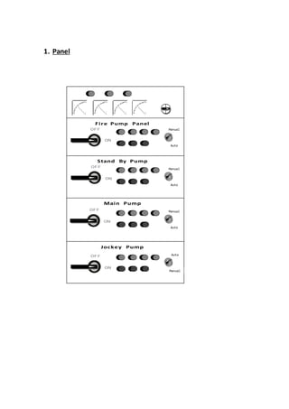
- 1. 1. Panel Fire Pump Panel Stand By Pump Main Pump Jockey Pump OFF ON OFF ON OFF ON OFF ON Manual Auto Manual Auto Manual Auto Auto Manual
- 2. Electricity comes to pump panels from ‘Fire Pump Panel’ through star and delta connections. ‘Star and Delta’ are power control switches which give a constant power supply to pumps. Primarily power supply goes through star connections and then delta connection will carry a non-interrupted constant power supply to pumps. At the top of panel, we can see 3 LED lamps which indicate Power ON/OFF and trouble. 3 Ampere meters and one volt meter are installed near at top portion of panel. There is a switch which helps us to know voltage in power supply. The voltage indicates by voltage meter as we control the volt meter knob. Pump can run either manually or automatically. There is a knob for controlling auto- manual function on each pump panel. Every panel is controlled by ON/OFF livers. 3 press switches and 4 LED bulbs are installed on every panel. ON Green Switch Green Light OFF Red Switch Red Light Reset Yellow Switch Yellow Light Manual mode - Blue Light Before starting pump, must check for voltage of power in three lines. We can check it by controlling voltage regulator switch which installed on top near voltage meter. The voltage must in between 360V and 440V. We are keeping the Jockey pump in auto mode and others in manual mode. Panel carries a high voltage power. Do not operate without knowledge and inappropriate condition. Pumps Three centrifugal pumps – Jockey Pump, Main Pump, Stand by Pump and one terrace mounted pump. Two types of pumps depend upon the suction method:- 1. Positive suction pumps & 2. Negative suction pumps. Positive Suction – Water coming directly from tank to suction head by gravitational force.
- 3. Negative Suction – Suction line with a foot valve. Priming should require in negative suction pumps. Here we are using positive displacement centrifugal pumps. Working In auto mode If a pressure drop in hydrant line below 7.5 bars, the Jockey pump starts automatically and maintains the line pressure as 7.5 bars. If pressure drop persists and the level decreases below 5 bars, the Main pump will start and gives a high pressure water supply. Jockey pump will automatically go off when main pump starts. Standby pump kept for an immediate use, when main pump failed in operation. It will start automatically if pressure drops below 2bars. Before switching off manually, ensure the Auto-Manual switch is in manual position. Then press the OFF switch (Red in color) Always ensure pump ampere level is 150 amps. In Manual mode Panel & Pump operating procedure Before operating always check for voltage level. ON the Fire pump panel by using ON/OFF liver. Ensure the Auto-Manual switch on each pump panels is in manual position. ON the pump panel by using ON/OFF liver. Then ON the pump by pressing ON switch (Green in color) Check the ampere for pump in ampere meter, installed at the top. The normal ampere level 150 amps. Before switching off manually, ensure the Auto-Manual switch is in manual position. Then press OFF switch (Red in color). Pump failure- Chances Voltage variation – The voltage level, a pump need to work safely is between 360V and 440V. If any difference in voltage do not ON the pump. It may burn. Closed valves – The Valves in hydrant lines may be in close position while running the pump. This situation may cause over heating in propeller side and will result in break down. Pump overheating – Main cause is the closed valves while pump running. Moisture content – If pump remains as unused, the coils / windings inside may get moisture. This condition will cause a short circuit in coils/windings and it will burn. Maintenance Run all the pumps once in a week.
- 4. Pump head calculation As per the law, the outlet water should reach at the top of the building from yard hydrant line. There is a calculation method to find the head capacity of pump to get the pressure for reaching the water from ground hydrant to top. For normal fire hydrant line (1 Hose reel hose + 1Hydrant point) Pump Head = Building height x 2 For Sprinkler system installed fire hydrant line Pump Head = Building height x 3 Horse Power is depends upon head capacity of pumps. It determines by manufactures of pumps. Hydrant Line Hydrant line consists of MS pipes, NRV’s, Butterfly Valves, Air releasing valves/vessels, pressure gauges, pressure switches, male/female couplings and hose boxes. Some major points NRV (Non Return valve) – Uses for preventing back water flow. Butterfly valve – Uses for control flow of water in line. Air releasing valve – Helps to release air inside hydrant lines. Air releasingvessel –Same use of Airreleasingvalve.Butit works more effectively than Air releasing valve. When an air lock happens in hydrant line, this vessel absorbs the air and releases it to atmosphere automatically/manually. Main cause of Air lock - The vacant space which happens bythe back flow of water from top of hydrant line, occupies air. Pressure Gauge – Helpstoknowthe pressure in line. These pressure gauges are connected to pressure switches which ON/OFF pumps. Pressure Switches – It gets the pressure level from pressure gauge and ON/OFF pumps. Hose Box – Twohoseswill be inhose boxes in yards. Once in 4months pressure test should do for hoses. Plaster of Paris powder can apply to hose against fungal infection.