Basics of Gas Turbine Power Plant
•Transferir como PPTX, PDF•
48 gostaram•23,224 visualizações

Basics of Gas Turbine Power Plant

Recomendados
Mais conteúdo relacionado
Mais procurados
Mais procurados (20)
Semelhante a Basics of Gas Turbine Power Plant
Semelhante a Basics of Gas Turbine Power Plant (20)
Mais de S.Vijaya Bhaskar
Mais de S.Vijaya Bhaskar (20)
Último
Último (20)
Basics of Gas Turbine Power Plant
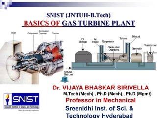
- 1. SNIST (JNTUH-B.Tech) BASICS OF GAS TURBINE PLANT Dr. VIJAYA BHASKAR SIRIVELLA M.Tech (Mech)., Ph.D (Mech)., Ph.D (Mgmt) Professor in Mechanical EngineeringSreenidhi Inst. of Sci. & Technology Hyderabad
- 2. Syllabus: GAS TURBINE PLANT Introduction – classification - construction – Layout with auxiliaries – Principles of working of closed and open cycle gas turbines. Combined Cycle Power Plants and comparison.
- 3. INTRODUCTION Gas turbines have been used for electricity generation in the periods of peak electricity demand Gas turbines can be started and stopped quickly enabling them to be brought into service as required to meet energy demand peaks. Small unit sizes and their low thermal efficiency restricted the opportunities for their wider use for electricity generation.
- 4. GAS TURBINE The Thermal efficiency of the gas turbine is 20 to 30% compared with the modern steam power plant 38 to 40%. In future it is possible to construct efficiencies in and around 45%. Following are the fields of Gas Turbine applications: Power Generation Aviation Oil and Gas industry Marine Propulsion A Gas Turbine is used in aviation and marine fields because it is self contained, light weight not requiring cooling water and fit into the overall shape of the structure. It is selected for the power generation because of its simplicity, lack of cooling water, needs quick installation and quick starting. It is used in oil and gas industry because of cheap supply of fuel and low installation cost. Limitations of the gas turbine: 1. They are not self starting 2. low efficiencies at part loads 3. non reversibility 4. Higher rotor speeds 5. Low overall plant efficiency.
- 8. GAS TURBINE Gas turbine plant is defined as “ in which the principle of the prime mover is of the turbine type and the working medium is a permanent gas”. Simple gas turbine plant consists of Turbine Compressor Combustor Auxiliary devices like starting device, lubricating pump, fuel pump, oil system and duct system. The working fluid is compressed in a compressor which is generally rotary, multistage type. Heat is added to the compressed fluid in the combustion chamber . This high energy fluid at high temperature and pressure then expands in the turbine thereby generating power. Part of the energy generated is consumed in driving the compressor and accessories and the rest is utilized in electrical energy.
- 9. GAS TURBINE TERMS PRESSURE RATIO: It is the ratio of cycle’s highest to its lowest pressure. Higher pressure at compressor discharge and lowest pressure at compressor in let pressure. High Pres from Compressor/Low Pres in Comp WORK RATIO: It is the ratio of net work output to the total work developed in the turbine. Network output/Total work AIR RATIO: Kg of air entering the compressor inlet per unit of cycle net output. i.e. kg/kwh COMPRESSOR EFFICIENCY: It is the ratio of work needed for ideal air compression through a given pressure range to work actually used by the compressor. Work needed for Ideal air compression/work actually used by compressor ENGINE EFFICIENCY : It is the ratio of work actually developed by the turbine expanding hot power gas through a given pressure range to that would be yielded for ideal expansion conditions. Actual work/ideal expan COMBUSTION EFFICIENCY: It is the ratio of heat actually released by 1 kg of fuel to heat that would be released by complete perfect combustion. THERMAL EFFICIENCY: It is the percentage of total energy input appearing as net work output of the cycle.
- 10. GAS TURBINE CLASSIFICATION There are two basic types of gas turbines – aero derivative and industrial. Aero derivative units are aircraft jet engines modified to drive electrical generators have a maximum output of 40 MW. These can produce full power within three minutes after start up. They are not suitable for base load operation. Industrial gas turbines range in sizes up to more than 260 MW. Depending on size, start up can take from 10 to 40 minutes to produce full output. Industrial gas turbines have a lower capital cost per kilowatt installed than aero derivative units and, because of their more robust construction, are suitable for base load operation.
- 11. GAS TURBINE POWER PLANTS CLASSIFICATION 1.By Application: Jet Propulsion Air craft Prop-Jets Peak Load Unit Stand by Unit Stationary End of Transmission Line Unit Base Load Unit Industrial Unit Locomotive Marine Transport 2.By Cycle: Open Closed Semi closed
- 12. GAS TURBINE POWER PLANTS CLASSIFICATION 3.According to Arrangement: Simple Single Shaft Multi Shaft Inter cooled Reheat Regenerative Combination 4.According to combustion: Continuous combustion Intermittent combustion 5.By Fuel: Solid fuel Liquid fuel Gaseous fuel
- 13. GAS TURBINE POWER PLANTS Classification of Gas Turbines Constant Pressure combustion Gas Turbine Constant volume combustion Gas Turbine Aero derivative units are aircraft jet engines modified to drive electrical generators have a maximum output of 40 MW. These can produce full power within three minutes after start up. They are not suitable for base load operation. Industrial gas turbines range in sizes up to more than 260 MW. Depending on size, start up can take from 10 to 40 minutes to produce full output. Industrial gas turbines have a lower capital cost per kilowatt installed than aero derivative units and, because of their more robust construction, are suitable for base load operation Open Cycle Closed Cycle
- 14. Advantages of Gas Turbine Power Plants over Diesel Plants Work developed per kg of air is more than diesel plant Less vibrations due to perfect balancing and no reciprocating parts Less space requirements Capital cost is less Higher mechanical efficiency Running speed of the turbine is large Lower installation and maintenance costs Torque characteristics of turbine plants are better than diesel plant Ignition and lubrication systems are simpler Specific Fuel Consumption (SFC) does not increase with time in gas turbine plant as rapidly in diesel plants Poor quality fuel can be used Light weigh with reference to Weight to power ratio is less for gas turbine power plants Smoke less combustion is achieved in gas power plants
- 15. Disadvantages of Gas Turbine Power Plants over Diesel Plants Poor part load efficiency Special metals and alloys are required for different components Special cooling methods required for cooling of turbine blades Short life Thermal efficiency is low Wide operating speeds the fuel control is difficult Needs to have speed reduction devices for higher operating speeds of turbine. Difficult to start a gas turbine compared to diesel engine Manufacturing of blades is difficult and costly Same output gas turbines produces the five times the exhaust gases than IC engines.
- 16. Advantages of Gas Turbine Power Plants over Steam Plants No ash handling Low capital cost and running costs Space requirement is less Fewer auxiliaries are used Can be built relatively quicker Can brought on load quickly to support peak loads Thermal efficiency of the gas turbine is higher than steam when working on top temperature (>5500C) Gas turbine plants quite economical for short running hours Storage of fuel is smaller and handling is easy. Less cooling water required for gas turbine plants compared to steam Weight per H.P. is far less Can be installed any where Control of gas turbine is much easier.
- 17. Gas Turbine Power Plant Layout with Auxiliaries Main Components of the Gas turbine plant layout are • Gas Turbine • Compressor • Combustor • Intercooler and Generator
- 18. GAS TURBINE Gas Turbine employs blades mounted on a shaft and enclosed in a casing. Flow of the fluid through the turbine is axial and tangential to the rotor. Basic requirements are light weight, high efficiency, reliability in operation, long working life. Large work output can be obtained per stage with high blade speeds when the blades are designed to sustain higher temperature. More stages of the turbine blades in the gas power plant helps to reduce the stress in the blades and increase the overall life of the turbine. Gas turbine blades are continuously subjected to the high temperature gases, so we need to cool the blades for long life. In air cooling the air is passed through the holes provided through the blade.
- 20. Working Principle of Gas Turbine Air is compressed(squeezed) to high pressure by a compressor. Then fuel and compressed air are mixed in a combustion chamber and ignited. Hot gases are given off, which spin the turbine wheels. Gas turbines burn fuels such as oil, natural gas and pulverized(powdered) coal. Gas turbines have three main parts: i) Air compressor ii) Combustion chamber iii) Turbine
- 21. 27 February 201921 Gas turbine power plant Air compressor: The air compressor and turbine are mounted at either end on a common shaft, with the combustion chamber between them. Gas turbines are not self starting. A starting motor is used. The air compressor sucks in air and compresses it, thereby increasing its pressure.
- 22. COMPRESSOR The axial flow compressors are used in gas turbine installations. An axial flow compressor consists of a series of rotor and stator stages with decreasing diameters along the flow of air. The blades are fixed on the rotors and the rotors are fixed on the shaft. The stator blades are fixed on the stator casing. The stator blades guide the airflow to the next rotor stage coming from the previous rotor stage. The air flows along the axis of the rotor. The K.E. is given to the air as it passes through the rotor and part of it is converted into pressure. An axial compressor is capable of delivering the constant volume of air over varying discharge pressures. These are well suited for large capacities at moderate pressures. If the impeller of a centrifugal compressor is designed to give an axial component of velocity at exit, the design becomes a mixed flow type.
- 23. COMPRESSOR The Centrifugal Compressor is superior to the axial flow machine in that high pressure ratio can be obtained in single stage machine, through at the cost of lower efficiency and increased frontal area.
- 24. COMBUSTOR
- 25. 27 February 201925 Gas turbine power plant Combustion chamber: In the combustion chamber, the compressed air combines with fuel and the resulting mixture is burnt. The greater the pressure of air, the better the fuel air mixture burns. Modern gas turbines usually use liquid fuel, but they may also use gaseous fuel, natural gas or gas produced artificially by gasification of a solid fuel.
- 26. 27 February 201926 Gas turbine power plant Turbine: Hot gases move through a multistage gas turbine. Like in steam turbine, the gas turbine also has stationary and moving blades. The stationary blades guide the moving gases to the rotor blades adjust its velocity. The shaft of the turbine is coupled to a generator.
- 27. TYPES OF GAS TURBINE POWER PLANTS The gas turbine power plants can be classified mainly into two categories. These are :open cycle gas turbine power plant and closed cycle gas turbine power plant. Open Cycle Gas Turbine Power Plant In this type of plant the atmospheric air is charged into the combustor through a compressor and the exhaust of the turbine also discharge to the atmosphere. Closed Cycle Gas Turbine Power Plant In this type of power plant, the mass of air is constant or another suitable gas used as working medium, circulates through the cycle over and over again.
- 28. OPEN CYCLE GAS TURBINE POWER PLANTAND ITS CHARACTERISTICS Gas turbines usually operate on an open cycle Air at ambient conditions is drawn into the compressor, where its temperature and pressure are raised. The high pressure air proceeds into the combustion chamber, where the fuel is burned at constant pressure. The high-temperature gases then enter the turbine where they expand to atmospheric pressure while producing power output. Some of the output power is used to drive the compressor. The exhaust gases leaving the turbine are thrown out (not re-circulated), causing the cycle to be classified as an open cycle
- 29. Methods of Improvement of Thermal Efficiency of Open Cycle Gas Turbine Plant 1.Regenerating (Regenerator) 2. Intercooling 3. Reheating
- 30. Regenerator The exhaust gasses from the turbine carry a large quantity of heat with them since their temperature is far above the ambient temperature. They can be used to heat air coming from the compressor there by reducing the mass of fuel supplied in the combustion chamber.
- 31. Regenerator
- 32. Intercooling A compressor utilizes the major percentage of power developed by the gas turbine. The work required by the compressor can be reduced by compressing the air in two stages and incorporation a intercooler between the two.
- 33. INTERCOOLER
- 34. Reheating The output of gas turbine can be improved by expanding the gasses in two stages with a reheater between the two. The H.P. turbine drives the compressor and the LP turbine provides useful power output.
- 35. CLOSED CYCLE GAS TURBINE POWER PLANT AND ITS CHARACTERISTICS The compression and expansion processes remain the same, but the combustion process is replaced by a constant-pressure heat addition process from an external source. The exhaust process is replaced by a constant- pressure heat rejection process to the ambient air.
- 36. 36 Closed cycle gas turbine power plant A closed cycle gas turbine is a turbine in which the air/working gas is circulated continuously within the turbine.
- 37. The components of this turbine are compressor, heating chamber, gas turbine which drives the generator and compressor, and a cooling chamber The closed cycle gas turbine works on the principle of Joule’s or Brayton’s cycle In this turbine, the gas is compressed isentropically and then passed into the heating chamber. The compressor generally used is of rotary type. The compressed air is heated with the help of some external source and then made to flow over the turbine blades. The turbine used here is of reaction type. The gas while flowing over the blades of the turbine, gets expanded. From the turbine the gas is passed to the cooling chamber. Here the gas is cooled at constant pressure with the help of circulating water to its original temperature. Now the gas is again made to flow through the compressor to repeat the process. Here the same gas is circulated again and again in the working of a closed cycle gas turbine.
- 38. OPEN CYCLE GAS TURBINE
- 39. A simple open cycle gas turbine consists of a compressor, combustion chamber and a turbine as shown in the below figure. The compressor takes in ambient fresh air and raises its pressure. Heat is added to the air in the combustion chamber by burning the fuel and raises its temperature. The heated gases coming out of the combustion chamber are then passed to the turbine where it expands doing mechanical work. Some part of the power developed by the turbine is utilized in driving the compressor and other accessories and remaining is used for power generation. Fresh air enters into the compressor and gases coming out of the turbine are exhausted into the atmosphere, the working medium need to be replaced continuously. This type of cycle is known as open cycle gas turbine plant and is mainly used in majority of gas turbine power plants as it has many inherent advantages.
- 40. Merits and Demerits of Closed Loop Cycle Turbine over Open Loop Cycle turbine Merits: Higher thermal efficiency Reduced size No contamination Improved heat transmission Lesser Fluid friction No loss in working medium Greater output Inexpensive fuel. Demerits: Complexity Large amount of cooling water is required. Dependent System Not economical for moving vehicles as weight /kW developed is high. Requires the use of very large air heater.
- 41. Combination of Gas Turbine Cycles Gas Turbine and Steam Power Plants: The combination of gas-turbine-steam cycle aims at utilizing the heat of exhaust gases from the gas turbine thus, improve the overall plant efficiency. The popular designs are: 1. Heating feed water with exhaust gases. 2. Employing the gases from a supercharged boiler to expand in the gas turbine. 3. Employing the gasses as combustion air in the steam boiler.
- 42. Heating feed water with exhaust gases. The output heat of the gas turbine flue gas is utilized to generate steam by passing it through a heat recovery steam generator (HRSG), so it can be used as input heat to the steam turbine power plant. This combination of two power generation cycles enhances the efficiency of the plant. While the electrical efficiency of a simple cycle plant power plant without waste heat utilization typically ranges between 25% and 40%, a CCPP can achieve electrical efficiencies of 60% and more.
- 43. Employing the gases from a supercharged boiler to expand in the gas turbine. The boiler furnace works under a pressure of about 5 bars and the gases are expanded in the gas turbine, the exhaust being used to heat feed water before being discharged through the stack. The heat transfer rate is very high as compared to conventional boiler due to high pressure of gases, and smaller size of steam generator is needed. No need of forced draught fans as the gases in furnace are already under pressure. Overall improvement in heat rate is 7%.
- 44. Employing the gases as combustion air in the steam boiler. Exhaust gases are used as preheated air for combustion in the boiler, results in 5% improvement in heat rate. The boiler is fed with supplementary fuel and air, and is made larger than conventional furnace.
- 45. Combined Gas Turbine and Diesel Power Plants The performance of diesel engine can be improved by combining it with exhaust driven gas turbine. Three combinations: 1. Turbo charging 2. Gas Generator 3. Compound engine
- 46. Turbo Charging / Supercharging This method is known as supercharging. The exhaust of the diesel engine is expanded in the gas turbine and the work output of the gas turbine is utilized to run a compressor which supplies the pressurized air to the diesel engine to increase its output.
- 47. Gas Generator The compressor which supplies the compressed air to the diesel engine is not driven from gas turbine but from the diesel engine through some suitable device. The output of diesel engine is consumed in driving the air compressor and gas turbine supplies the power.
- 48. Compound Engine The air compressor is driven from both diesel engine and gas turbine through a suitable gearing and power output is taken from the diesel engine shaft.