Enterprise Network Manager: the Router-On-A-stick
•Transferir como DOC, PDF•
0 gostou•532 visualizações

Leading Cisco networking products distributor-3network.com Enterprise Network Manager the Router-On-A-stick

Recomendados
Recomendados
Mais conteúdo relacionado
Mais procurados
Mais procurados (20)
Destaque
Semelhante a Enterprise Network Manager: the Router-On-A-stick
Semelhante a Enterprise Network Manager: the Router-On-A-stick (20)
Mais de 3Anetwork com
Mais de 3Anetwork com (20)
Último
Último (20)
Enterprise Network Manager: the Router-On-A-stick
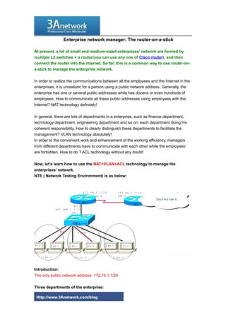
- 1. Enterprise network manager: The router-on-a-stick At present, a lot of small and medium-sized enterprises’ network are formed by multiple L2 switches + a router(you can use any one of Cisco router), and then connect the router into the internet. So far, this is a common way to use router-on- a-stick to manage the enterprise network. In order to realize the communications between all the employees and the Internet in the enterprises, it is unrealistic for a person using a public network address. Generally, the enterprise has one or several public addresses while has dozens or even hundreds of employees. How to communicate all these public addresses using employees with the Internet? NAT technology definitely! In general, there are lots of departments in a enterprise, such as finance department, technology department, engineering department and so on, each department doing his coherent responsibility. How to clearly distinguish these departments to facilitate the management? VLAN technology absolutely! In order to the convenient work and enhancement of the working efficiency, managers from different departments have to communicate with each other while the employees’ are forbidden. How to do ? ACL technology without any doubt! Now, let’s learn how to use the NAT+VLAN+ACL technology to manage the enterprises’ network. NTE ( Network Testing Environment) is as below: Introduction: The only public network address: 172.16.1.1/24 Three departments of the enterprise: 1
- 2. Finance department (PC1 for manager) Technology department (PC3 for manager) Engineering department (PC5 for manager) IP: PC1:192.168.1.2/24PC2:192.168.1.3/24 PC3:192.168.2.2/24PC4:192.168.2.3/24 PC5:192.168.3.2/24PC6:192.168.3.3/24 Test for purpose: By NAT configuration, all the computers will be connected to communicate with Internet through the only public network address. To divide various departments through VLAN configuration and to realize the intercommunications among managers from different departments through ACL configuration while not among the employees. Ok, let’s down to work as we’ve known the intention. Firstly, basic configuration on R1 and R2 (dot1Q is needed to encapsulate for sub- interface configuration as we have to use routing process among VLANs.) R1 Router>en Router#conft Enterconfiguration commands, one per line. End withCNTL/Z. Router(config)#host r1 r1(config)#int s0/0 r1(config-if)#ip addr 172.16.1.1 255.255.255.0 r1(config-if)#no shut %LINK-5-CHANGED: Interface Serial0/0, changed state to up r1(config-if)#clock rate 64000 %LINEPROTO-5-UPDOWN: Line protocol on Interface Serial0/0, changedstate to u r1(config-if)#exit r1(config)#int f0/0 r1(config-if)#no ip addr r1(config-if)#no shut r1(config-if)#exit r1(config)#intf0/0.1 (sub-interface configuration) r1(config-subif)#encapsulation dot1Q2 (dot1Q is needed to encapsulate for sub-interface configuration) r1(config-subif)#ip addr 192.168.1.1 255.255.255.0 r1(config-subif)#no shut r1(config-subif)#exit 2
- 3. r1(config)#intf0/0.2 (sub-interface configuration) r1(config-subif)#encapsulation dot1Q3 (dot1Q is needed to encapsulate for sub-interface configuration) r1(config-subif)#ip addr 192.168.2.1 255.255.255.0 r1(config-subif)#no shut r1(config-subif)#exit r1(config)#intf0/0.3 (sub-interface configuration) r1(config-subif)#encapsulation dot1Q4 (dot1Q is needed to encapsulate for sub-interface configuration) r1(config-subif)#ip addr 192.168.3.1 255.255.255.0 We just need the IP configuration on S0/0 port of R2 cause we take R2 as public network. R2 Router>en Router#conft Enterconfiguration commands, one per line. End withCNTL/Z. Router(config)#host r2 r2(config)#int s0/0 r2(config-if)#ip addr 172.16.1.2 255.255.255.0 r2(config-if)#no shut Secondly, to have all the employees passed through the only public network—IP 172.16.1.1/24 for Internetcommunications. R1 r1(config)#ip nat pool internet 172.16.1.1 172.16.1.1 netmask255.255.255.0 r1(config)#access-list 10 permit 192.168.0.00.0.255.255 r1(config)#ip nat inside source list 10 pool internet overload r1(config)#int s0/0 r1(config-if)#ip nat outside r1(config-if)#exit r1(config)#int f0/0 r1(config-if)#ip nat inside To divide various departments through VLAN configuration and to realize the intercommunications among managers from different departments through ACL configuration while not among the employees. Sw Switch>en 3
- 4. Switch#conft Enterconfiguration commands, one per line. End withCNTL/Z. Switch(config)#int f0/1 Switch(config-if)#switchport modetrunk (Trunk link configuration) %LINEPROTO-5-UPDOWN: Line protocol on Interface FastEthernet0/1,changed state to down %LINEPROTO-5-UPDOWN: Line protocol on Interface FastEthernet0/1,changed state to up Switch(config-if)#exit Switch(config)#vlan2 (VLAN 2 setting up) Switch(config-vlan)#namegongchengbu (Vlan2: Engineering department) Switch(config-vlan)#exit Switch(config)#vlan3 (VLAN 3 setting up) Switch(config-vlan)#namecaiwubu (VLAN3: Finance department) Switch(config-vlan)#exit Switch(config-vlan)#vlan4 (VLAN 4 setting up) Switch(config-vlan)#namejishubu (VLAN4: Technology department) Switch(config-vlan)#exit Switch(config)#int f0/2 Switch(config-if)#switchport access vlan2 (Member adding to VLAN 2 manually) Switch(config-if)#exit Switch(config)#int f0/3 Switch(config-if)#switchport access vlan 2 Switch(config-if)#exit Switch(config)#int f0/4 Switch(config-if)#switchport access vlan3 (Member adding to VLAN 3 manually) Switch(config-if)#exit Switch(config)#int f0/5 Switch(config-if)#switchport access vlan 3 Switch(config-if)#exit Switch(config)#int f0/6 Switch(config-if)#switchport access vlan4 (Member adding to VLAN 4 manually) Switch(config-if)#exit Switch(config)#int f0/7 Switch(config-if)#switchport access vlan 4 Switch(config-if)#exit The definition of ACL (Access Control List): Be careful for ACL definition and you’d better put the most peculiar ACL on the top. Note: The interface binding is needed if the ACL can be applied. R1 r1(config)#access-list 10 permit 192.168.2.2 0.0.0.0 r1(config)#access-list 10 deny 192.168.2.0 0.0.0.255 4
- 5. r1(config)#access-list 10 permit 192.168.3.2 0.0.0.0 r1(config)#access-list 10 deny 192.168.3.0 0.0.0.255 r1(config)#access-list 10 permit any r1(config)#int f0/0.1 r1(config-subif)#ip access-group 10 out r1(config-subif)#exit r1(config)#access-list 11 permit 192.168.1.2 0.0.0.0 r1(config)#access-list 11 deny 192.168.1.0 0.0.0.255 r1(config)#access-list 11 permit 192.168.3.2 0.0.0.0 r1(config)#access-list 11 deny 192.168.3.0 0.0.0.255 r1(config)#access-list 11 permit any r1(config)#int f0/0.2 r1(config-subif)#ip access-group 11 out r1(config-subif)#exit r1(config)#access-list 12 permit 192.168.1.2 0.0.0.0 r1(config)#access-list 12 deny 192.168.1.0 0.0.0.255 r1(config)#access-list 12 permit 192.168.2.2 0.0.0.0 r1(config)#access-list 12 deny 192.168.2.0 0.0.0.255 r1(config)#access-list 12 permit any r1(config)#int f0/0.3 r1(config-subif)#ip access-group 12 out r1(config-subif)#exit Now, all the employees can intercommunicates after configuration. PC>ping 172.16.1.2 Pinging172.16.1.2 with 32 bytes of data: Replyfrom 172.16.1.2: bytes=32 time=94ms TTL=254 Reply from172.16.1.2: bytes=32 time=94ms TTL=254 Reply from172.16.1.2: bytes=32 time=94ms TTL=254 Reply from172.16.1.2: bytes=32 time=90ms TTL=254 Pingstatistics for 172.16.1.2: Packets: Sent = 4, Received = 4, Lost = 0 (0% loss), Approximateround trip times in milli-seconds: Minimum =90ms, Maximum = 94ms, Average = 93ms The intercommunications among managers from different departments (PC1, PC3 and PC5) have been realized after configuration. PC1>ping 192.168.2.2 Pinging192.168.2.2 with 32 bytes of data: Replyfrom 192.168.2.2: bytes=32 time=125ms TTL=127 Reply from192.168.2.2: bytes=32 time=110ms TTL=127 5
- 6. Reply from192.168.2.2: bytes=32 time=110ms TTL=127 Reply from192.168.2.2: bytes=32 time=125ms TTL=127 Pingstatistics for 192.168.2.2: Packets: Sent = 4, Received = 4, Lost = 0 (0% loss), Approximateround trip times in milli-seconds: Minimum =110ms, Maximum = 125ms, Average = 117ms PC1 PING PC5 PC1>ping 192.168.3.2 Pinging192.168.3.2 with 32 bytes of data: Replyfrom 192.168.3.2: bytes=32 time=111ms TTL=127 Reply from192.168.3.2: bytes=32 time=120ms TTL=127 Reply from192.168.3.2: bytes=32 time=111ms TTL=127 Reply from192.168.3.2: bytes=32 time=105ms TTL=127 Pingstatistics for 192.168.3.2: Packets: Sent = 4, Received = 4, Lost = 0 (0% loss), Approximateround trip times in milli-seconds: Minimum = 105ms, Maximum = 120ms, Average = 111ms PC3 PING PC5 PC3>ping 192.168.3.2 Pinging192.168.3.2 with 32 bytes of data: Replyfrom 192.168.3.2: bytes=32 time=125ms TTL=127 Reply from192.168.3.2: bytes=32 time=125ms TTL=127 Reply from192.168.3.2: bytes=32 time=109ms TTL=127 Reply from192.168.3.2: bytes=32 time=94ms TTL=127 Pingstatistics for 192.168.3.2: Packets: Sent = 4, Received = 4, Lost = 0 (0% loss), Approximateround trip times in milli-seconds: Minimum = 94ms, Maximum = 125ms, Average = 113ms There is no intercommunications among employees.(PC2,PC4 and PC6) PC2 PING PC4 PC2>ping 192.168.2.3 Pinging192.168.2.3 with 32 bytes of data: Requesttimed out. Requesttimed out. Requesttimed out. Requesttimed out. Pingstatistics for 192.168.2.3: Packets: Sent = 4, Received = 0, Lost = 4 (100% loss), PC2 PING PC6 6
- 7. PC2>ping 192.168.3.3 Pinging192.168.3.3 with 32 bytes of data: Requesttimed out. Requesttimed out. Requesttimed out. Requesttimed out. Pingstatistics for 192.168.3.3: Packets:Sent = 4, Received = 0, Lost = 4 (100% loss), PC4 PING PC 6 PC4>ping 192.168.3.3 Pinging192.168.3.3 with 32 bytes of data: Requesttimed out. Requesttimed out. Requesttimed out. Requesttimed out. Pingstatistics for 192.168.3.3: Packets:Sent = 4, Received = 0, Lost = 4 (100% loss), We get to our goals by all configurations as above: All the employees can intercommunicate with Internet through one public network address. Managers from different departments can communicate with each other while not among the employees. We recommend you to use the Layer 3 Switches for Distribution Layer and Core Switch and then connect to the Internet by routers. More related: Cisco Integrated Services Router Generation 2 The available power supplies for the Cisco routers How to recover password for the Cisco 1900 and 2900 router? The Difference of The Cisco Catalyst 2900 and Cisco Catalyst 1900 More Cisco products and Reviews you can visit: http://www.3anetwork.com/blog 3Anetwork.com is a world leading Cisco networking products wholesaler, we wholesale original new Cisco networking equipments, including Cisco Catalyst switches, Cisco 7
- 8. routers, Cisco firewalls, Cisco wireless products, Cisco modules and interface cards products at competitive price and ship to worldwide. Our website: http://www.3anetwork.com Telephone: +852-3069-7733 Email: info@3Anetwork.com Address: 23/F Lucky Plaza, 315-321 Lockhart Road, Wanchai, Hongkong 8