SlideShare uma empresa Scribd logo
1 de 44
Baixar para ler offline
Systems Operation
C27 Industrial and C32 Industrial and Petroleum Engines
General Information
SMCS - 1000
Part Number -
S/N - TWM1-UP
Shutdown SIS
Previous Screen
Product: NO EQUIPMENT SELECTED
Model: NO EQUIPMENT SELECTED
Configuration: NO EQUIPMENT SELECTED
Media Number -RENR9798-03 Publication Date -01/08/2008 Date Updated -26/08/2008
i03477244
Illustration 1 g01205382
Typical example
(1) Electronic Control Module (ECM)
(2) Turbocharger
(3) Primary fuel filter and water separator
(4) Engine oil filter base
Página 1
The Mechanical Electronic Unit Injector (MEUI) fuel system is used on this engine. The MEUI fuel system
eliminates many of the mechanical components that are used in a pump and lines. The electronic control and
mechanical actuation provides increased control of the timing and increased control of the fuel injection
pressure. The timing advance is achieved by precise control of the unit injector timing. Engine speed is
controlled by adjusting the injection duration. A special speed-timing wheel provides information to the
Electronic Control Module (ECM) for detection of cylinder position and engine speed.
The engine has built-in diagnostics in order to ensure that all of the components are operating properly. In the
event of a system component failure, the operator will be alerted to the condition via the diagnostic lamp that is
located on the control panel. Caterpillar Electronic Technician (ET) can be used to read the numerical code of
the faulty component or condition. Intermittent faults are also logged and stored in memory.
Starting the Engine
The engine's ECM will automatically provide the correct amount of fuel in order to start the engine. Do not
hold the throttle down while the engine is cranking. If the engine fails to start in twenty seconds, release the
starting switch. Allow the starting motor to cool for two minutes before using the starting motor again.
Cold Mode Operation
The ECM will set the cold start strategy when the coolant temperature is below 20 °C (68 °F).
When the cold start strategy is activated, low idle rpm will be increased and engine power will be limited.
Cold mode operation will be deactivated when any of the following conditions have been met:
Coolant temperature reaches 20 °C (68 °F).
The engine has been running for twelve minutes.
Cold mode operation uses a modified control map, that is stored in the ECM, in order to adjust the fuel
injection timing and the injection duration for white smoke cleanup. The engine will usually exit the cold mode
operation before the walk-around inspection is completed. During cold mode operation, the engine will remain
at the elevated rpm that has been specified for the engine.
After the cold mode is completed, the engine should be operated at low rpm until normal operating
temperature is reached. The engine will reach normal operating temperature faster when the engine is operated
at low rpm and low power demand.
Customer Specified Parameters
The engine is capable of being programmed for several customer specified parameters. For a brief explanation
of each of the customer specified parameters, refer to the Operation and Maintenance Manual for your engine.
(5) Engine oil filters
(6) Secondary fuel filter and fuel priming pump
(7) Exhaust manifold
(8) Flywheel housing
NOTICE
Excessive ether (starting fluid) can cause piston and ring damage. Use
ether for cold weather starting purposes only.
Página 2
Copyright 1993 - 2009 Caterpillar Inc.
All Rights Reserved.
Private Network For SIS Licensees.
Mon Sep 14 11:48:13 EST 2009
Página 3
Systems Operation
C27 Industrial and C32 Industrial and Petroleum Engines
General Information
SMCS - 1000
Part Number -
S/N - SMP1-UP
Part Number -
S/N - TLD1-UP
Part Number -
S/N - B2C1-UP
Shutdown SIS
Previous Screen
Product: NO EQUIPMENT SELECTED
Model: NO EQUIPMENT SELECTED
Configuration: NO EQUIPMENT SELECTED
Media Number -RENR9798-03 Publication Date -01/08/2008 Date Updated -26/08/2008
i02428487
Página 4
The Mechanical Electronic Unit Injector (MEUI) fuel system eliminates many of the mechanical components
that are used in a pump-and-line system. The electronic control and mechanical actuation also provide
increased control of the timing and increased control of the fuel injection pressure. The timing advance is
achieved by precise control of the unit injector timing. Engine speed is controlled by adjusting the injection
duration. A special speed-timing wheel provides information to the Electronic Control Module (ECM) for
Illustration 1 g01164605
(1) Turbocharger
(2) Exhaust outlet
(3) Electronic Control Module (ECM)
(4) Primary fuel filter and water separator
(5) Secondary fuel filter and fuel priming pump
(6) Engine oil filters
(7) Oil pan
(8) Flywheel housing
(9) Exhaust manifold
Página 5
detection of cylinder position and engine speed.
The engine has built-in diagnostics in order to ensure that all of the components are operating properly. In the
event of a system component failure, the operator will be alerted to the condition via the diagnostic lamp that is
located on the control panel. Caterpillar Electronic Technician (ET) can be used to read the numerical code of
the faulty component or condition. Intermittent faults are also logged and stored in memory.
Starting the Engine
The engine's ECM will automatically provide the correct amount of fuel in order to start the engine. Do not
hold the throttle down while the engine is cranking. If the engine fails to start in twenty seconds, release the
starting switch. Allow the starting motor to cool for two minutes before using the starting motor again.
Cold Mode Operation
The ECM will set the cold start strategy when the coolant temperature is below 20 °C (68 °F).
When the cold start strategy is activated, low idle rpm will be increased and engine power will be limited.
Cold mode operation will be deactivated when any of the following conditions have been met:
Coolant temperature reaches 20 °C (68 °F).
The engine has been running for twelve minutes.
Cold mode operation uses a modified control map, that is stored in the ECM, in order to adjust the fuel
injection timing and the injection duration for white smoke cleanup. The engine will usually exit the cold mode
operation before the walk-around inspection is completed. During cold mode operation, the engine will remain
at the elevated rpm that has been specified for the engine.
After the cold mode is completed, the engine should be operated at low rpm until normal operating
temperature is reached. The engine will reach normal operating temperature faster when the engine is operated
at low rpm and low power demand.
Customer Specified Parameters
The engine is capable of being programmed for several customer specified parameters. For a brief explanation
of each of the customer specified parameters, refer to the Operation and Maintenance Manual for your engine.
NOTICE
Excessive ether (starting fluid) can cause piston and ring damage. Use
ether for cold weather starting purposes only.
Copyright 1993 - 2009 Caterpillar Inc.
All Rights Reserved.
Private Network For SIS Licensees.
Mon Sep 14 11:50:22 EST 2009
Página 6
Systems Operation
C27 Industrial and C32 Industrial and Petroleum Engines
Electronic Control System Components
SMCS - 1900
Part Number -
S/N - TWM1-UP
Shutdown SIS
Previous Screen
Product: NO EQUIPMENT SELECTED
Model: NO EQUIPMENT SELECTED
Configuration: NO EQUIPMENT SELECTED
Media Number -RENR9798-03 Publication Date -01/08/2008 Date Updated -26/08/2008
i03211762
Illustration 1 g01205842
Top view
(1) Intake manifold air temperature sensor
Página 7
(2) Intake manifold pressure sensor
(3) Coolant temperature sensor
(4) Atmospheric pressure sensor
(5) Secondary engine speed/timing sensor
(6) Coolant level sensor
(7) Oil pressure sensor
(8) Electronic Control Module (ECM)
Illustration 2 g01387178
Front view
(9) Primary engine speed/timing sensor
Página 8
The electronic control system is integrally designed into the engine's fuel system and the engine's air inlet and
exhaust system in order to electronically control the fuel delivery. The electronic control system provides
better timing control and fuel air ratio control in comparison to conventional mechanical engines. Injection
timing is achieved by the precise control of the fuel injectors. Engine speed is controlled by adjusting the
injection duration. The Electronic Control Module (ECM) energizes the unit injector solenoids in order to start
the injection of fuel. Also, the ECM de-energizes the unit injector solenoids in order to stop the injection of
fuel.
Refer to Systems Operation/Testing And Adjusting, "Fuel System" for a complete explanation of the fuel
injection process.
The engine uses the following three types of electronic components:
Input component
Control component
Illustration 3 g01387177
Section A-A
(10) Fuel pressure sensor
(11) Fuel temperature sensor
Página 9
Output component
An input component is one that sends an electrical signal to the ECM. The signal that is sent varies in either of
the following ways:
Voltage
Frequency
Pulse width
The variation of the signal is in response to a change in some specific system of the engine. Some specific
examples of an input component are the engine speed-timing sensors, and the coolant temperature sensor. The
ECM interprets the signal from the input component as information about the condition, environment, or
operation of the engine.
An ECM receives the input signals from the input components. Electronic circuits inside the control
component evaluate the signals from the input components. These electronic circuits also supply electrical
energy to the output components of the system. The electrical energy that is supplied to the output components
is based on predetermined combinations of input signal values.
An output component is one that is operated by a control module. The output component receives electrical
energy from the control group. The output component uses electrical energy to make an adjustment in one of
the engine's systems. An output component may also provide information to the operator.
As an example, a moving solenoid plunger will perform work. By performing work, the component has
functioned in order to regulate the engine.
As an example, a control panel light or an alarm will provide information to the operator of the engine.
These electronic components provide the ability to electronically control the engine operation. Engines with
electronic controls offer the following advantages:
Improvement in performance
Improvement in fuel consumption
Reduction in emissions levels
Various sensors feed data to the ECM. The following sensors are used by the ECM for data:
Engine coolant temperature
Engine oil pressure
Atmospheric pressure
Primary speed/timing sensor
Secondary speed/timing sensor
Intake manifold air pressure
Intake manifold air temperature
The ECM processes the data. Then, the ECM sends an electronic signal to the fuel injector. The signal will
control the amount of fuel that is injected into the cylinder. This will optimize the efficiency and the
performance of the engine.
Página 10
Data Link
A data link is used for the following items:
Communicate engine information.
Communicate with Caterpillar Electronic Technician (ET).
Calibrate the electronic engine control system.
Troubleshoot the electronic engine control system.
Program the electronic engine control system.
The data link is used to communicate engine information to other electronic control systems. Also, the data
link can interface with Cat ET.
Cat ET can be used to program the customer specified parameters. The tool is plugged into the data link
connector. This allows Cat ET to communicate with the ECM. Also, Cat ET can be used to display the real
time values of all the information that is available on the data link. This will help diagnose engine problems.
Electronic Control Module (ECM)
The engine uses an ECM. The ECM is a microprocessor based device. The ECM is mounted on the top of the
front valve cover on the left side of the engine.
Illustration 4 g01381771
Electronic Control Module (ECM)
Página 11
The inputs and the outputs to the ECM are designed to withstand short circuits without damage to the control
module. The electronic engine control system has the following features that are designed into the system.
Resistance to radio frequency
Resistance to electromagnetic interference
The system has passed tests for interference by two-way radios and by switching noise.
The ECM power supply provides electrical power to all engine mounted sensors and actuators. The following
precautions have been designed into the ECM.
Reverse voltage polarity protection
Swings or surges of the voltage in the power system due to sudden alternator load
The ECM also monitors all sensor inputs and the ECM provides the correct outputs in addition to acting as a
power supply. Also, the ECM ensures the desired engine operation.
The ECM is programmed with a selected factory engine rating. The ECM memory contains a personality
module identification code. This code is used to avoid unauthorized tampering or switching of personality
modules and other pertinent manufacturing information.
The wiring harness provides communications to the following areas:
ECM
Various sensors
Data link connector
Engine connectors
The ECM is programmed to perform the following functions:
Diagnostic tests on all inputs
Diagnostic tests on all outputs
Identify a faulty circuit.
Once a fault is detected, the fault can be displayed on a diagnostic lamp. The diagnostic code can be read by
using Cat ET. A multimeter can be used to check most problems. Also, a multimeter can be used to
troubleshoot most problems. The ECM will record most diagnostic codes that are generated during engine
operation. These logged codes or intermittent codes can be read by Cat ET.
Copyright 1993 - 2009 Caterpillar Inc.
All Rights Reserved.
Private Network For SIS Licensees.
Mon Sep 14 11:52:03 EST 2009
Página 12
Systems Operation
C27 Industrial and C32 Industrial and Petroleum Engines
Electronic Control System Components
SMCS - 1900
Part Number -
S/N - SMP1-UP
Part Number -
S/N - TLD1-UP
Part Number -
S/N - B2C1-UP
Shutdown SIS
Previous Screen
Product: NO EQUIPMENT SELECTED
Model: NO EQUIPMENT SELECTED
Configuration: NO EQUIPMENT SELECTED
Media Number -RENR9798-03 Publication Date -01/08/2008 Date Updated -26/08/2008
i03211767
Página 13
Illustration 1 g01157677
Top view of engine
(1) Intake manifold air temperature sensor
(2) Intake manifold pressure sensor
(3) Coolant temperature sensor
(4) Atmospheric pressure sensor
(5) Electronic Control Module (ECM)
(6) Fuel pressure sensor
(7) Fuel differential pressure switch
(8) Fuel temperature sensor
Página 14
The electronic control system is integrally designed into the engine's fuel system and the engine's air inlet and
exhaust system in order to electronically control the fuel delivery. The electronic control system provides
better timing control and fuel air ratio control in comparison to conventional mechanical engines. Injection
timing is achieved by the precise control of the fuel injectors. Engine speed is controlled by adjusting the
injection duration. The Electronic Control Module (ECM) energizes the unit injector solenoids in order to start
the injection of fuel. Also, the ECM de-energizes the unit injector solenoids in order to stop the injection of
fuel.
Refer to Systems Operation/Testing And Adjusting, "Fuel System" for a complete explanation of the fuel
injection process.
The engine uses the following three types of electronic components:
Input component
Illustration 2 g01157719
Front view
(9) Engine oil pressure sensor
(10) Secondary speed/timing sensor
(11) Primary speed/timing sensor
Página 15
Control component
Output component
An input component is one that sends an electrical signal to the ECM. The signal that is sent varies in either of
the following ways:
Voltage
Frequency
Pulse width
The variation of the signal is in response to a change in some specific system of the engine. Some specific
examples of an input component are the engine speed-timing sensors, and the coolant temperature sensor. The
ECM interprets the signal from the input component as information about the condition, environment, or
operation of the engine.
An ECM receives the input signals from the input components. Electronic circuits inside the control
component evaluate the signals from the input components. These electronic circuits also supply electrical
energy to the output components of the system. The electrical energy that is supplied to the output components
is based on predetermined combinations of input signal values.
An output component is one that is operated by a control module. The output component receives electrical
energy from the control group. The output component uses electrical energy to make an adjustment in one of
the engine's systems. An output component may also provide information to the operator.
As an example, a moving solenoid plunger will perform work. By performing work, the component has
functioned in order to regulate the engine.
As an example, a control panel light or an alarm will provide information to the operator of the engine.
These electronic components provide the ability to electronically control the engine operation. Engines with
electronic controls offer the following advantages:
Improvement in performance
Improvement in fuel consumption
Reduction in emissions levels
Various sensors feed data to the ECM. The following sensors are used by the ECM for data:
Engine coolant temperature
Engine oil pressure
Atmospheric pressure
Primary speed/timing sensor
Secondary speed/timing sensor
Fuel temperature
Fuel pressure
Intake manifold air pressure
Página 16
Intake manifold air temperature
The ECM processes the data. Then, the ECM sends an electronic signal to the fuel injector. The signal will
control the amount of fuel that is injected into the cylinder. This will optimize the efficiency and the
performance of the engine.
Data Link
A data link is used for the following items:
Communicate engine information.
Communicate with Caterpillar Electronic Technician (ET).
Calibrate the electronic engine control system.
Troubleshoot the electronic engine control system.
Program the electronic engine control system.
The data link is used to communicate engine information to other electronic control systems. Also, the data
link can interface with Cat ET.
Cat ET can be used to program the customer specified parameters. The tool is plugged into the data link
connector. This allows Cat ET to communicate with the ECM. Also, Cat ET can be used to display the real
time values of all the information that is available on the data link. This will help diagnose engine problems.
Electronic Control Module (ECM)
The engine uses an ECM. The ECM is a microprocessor based device. The ECM is mounted on the top of the
front valve cover on the left side of the engine.
The inputs and the outputs to the ECM are designed to withstand short circuits without damage to the control
module. The electronic engine control system has the following features that are designed into the system.
Illustration 3 g01118503
Electronic Control Module (ECM)
Página 17
Resistance to radio frequency
Resistance to electromagnetic interference
The system has passed tests for interference by two-way radios and by switching noise.
The ECM power supply provides electrical power to all engine mounted sensors and actuators. The following
precautions have been designed into the ECM.
Reverse voltage polarity protection
Swings or surges of the voltage in the power system due to sudden alternator load
The ECM also monitors all sensor inputs and the ECM provides the correct outputs in addition to acting as a
power supply. Also, the ECM ensures the desired engine operation.
The ECM is programmed with a selected factory engine rating. The ECM memory contains a personality
module identification code. This code is used to avoid unauthorized tampering or switching of personality
modules and other pertinent manufacturing information.
The wiring harness provides communications to the following areas:
ECM
Various sensors
Data link connector
Engine connectors
The ECM is programmed to perform the following functions:
Diagnostic tests on all inputs
Diagnostic tests on all outputs
Identify a faulty circuit.
Once a fault is detected, the fault can be displayed on a diagnostic lamp. The diagnostic code can be read by
using Cat ET. A multimeter can be used to check most problems. Also, a multimeter can be used to
troubleshoot most problems. The ECM will record most diagnostic codes that are generated during engine
operation. These logged codes or intermittent codes can be read by Cat ET.
Copyright 1993 - 2009 Caterpillar Inc.
All Rights Reserved.
Private Network For SIS Licensees.
Mon Sep 14 12:09:33 EST 2009
Página 18
Systems Operation
C27 Industrial and C32 Industrial and Petroleum Engines
Fuel System
SMCS - 1250
Shutdown SIS
Previous Screen
Product: NO EQUIPMENT SELECTED
Model: NO EQUIPMENT SELECTED
Configuration: NO EQUIPMENT SELECTED
Media Number -RENR9798-03 Publication Date -01/08/2008 Date Updated -26/08/2008
i02776678
Illustration 1 g01155662
(1) Cylinder head
(2) Unit injector
(3) Fuel transfer pump
(4) Secondary fuel filter and priming pump
(5) Fuel tank
(6) Electronic Control Module (ECM)
(7) Primary fuel filter and water separator
Página 19
The fuel supply circuit is a conventional design for unit injector diesel engines. The system consists of the
following major components that are used to deliver low pressure fuel to the unit injectors:
Fuel tank - The fuel tank is used to store the fuel.
Fuel priming pump - The fuel priming pump is used to evacuate the air from the fuel system. As the air is
removed the system fills with fuel.
Fuel filters - The primary fuel filter is used to remove abrasive material and contamination from the fuel
system that may be large enough to damage the fuel transfer pump. The secondary fuel filter is used to remove
abrasive material and contamination as small as two microns that could damage the injectors.
Supply lines and return lines - Supply lines and return lines are used to deliver the fuel to the different
components.
The purpose of the low pressure fuel supply circuit is to supply fuel that has been filtered to the fuel injectors
at a rate that is constant and a pressure that is constant. The fuel system is also utilized to cool components
such as the fuel injectors and the Electronic Control Module (ECM).
Once the injectors receive the low pressure fuel, the fuel is pressurized again before the fuel is injected into the
cylinder. The unit injector uses mechanical energy that is provided by the camshaft to achieve pressures that
can be in excess of 200000 kPa (30000 psi).
Control of the fuel delivery is managed by the engine's ECM. Data from several of the engine systems is
collected by the ECM and processed in order to manage these aspects of fuel injection control:
Injection timing
Fuel injection timing advance
Injection duration
Engine cold mode status
The mechanical electronic fuel system relies on a large amount of data from the other engine systems. The data
that is collected by the ECM will be used in order to provide optimum performance of the engine.
Low Pressure Fuel Supply Circuit
The flow of fuel through the system begins at fuel tank (5) . Fuel is drawn through the primary fuel filter and
water separator (7) from the fuel tank by fuel transfer pump (3) . The fuel transfer pump incorporates a check
valve that will allow fuel to flow around the gears of the pump during priming of the fuel system. The fuel
transfer pump also incorporates a pressure relief valve. The pressure relief valve is used in order to protect the
fuel system from extreme pressure.
The fuel transfer pump is designed in order to produce an excess fuel flow throughout the fuel system. The
excess fuel flow is used by the system to cool the fuel system components. The excess fuel flow also purges
any air from the fuel system during operation. Air that can become trapped in the fuel system can cause
cavitation that may damage the components of the unit injector.
After leaving the fuel transfer pump, the fuel flows to the ECM (6) in order to cool the ECM. Next, the fuel
flows to the secondary fuel filter and fuel priming pump (4) . The fuel priming pump is located on the fuel
filter base. The fuel filter base and the secondary fuel filter also incorporate a siphon break that prevents fuel
from draining from the fuel system when the engine is not in operation. The priming pump is a hand operated
pump that directs the flow of fuel during the priming pump's operation. The secondary fuel filter is a two
micron fuel filter. The fuel is filtered in order to remove small abrasive particles that will cause premature wear
to fuel system components. The filtered fuel then flows out of the fuel filter and returns to the passages in the
fuel filter base. Prior to exiting the fuel filter base, the fuel pressure and the fuel temperature are sampled by
the fuel pressure sensor and by the fuel temperature sensor. The signals that are generated by the sensors are
Página 20
used by the ECM in order to monitor the condition of the engine's components. This information is also used to
adjust the fuel delivery of the engine in order to optimize efficiency.
The fuel is then transfered by the fuel supply lines to the cylinder head (1) . Only a portion of the fuel that is
supplied to the fuel injectors is used for engine operation. This unused fuel is discharged into the return
passages of the fuel gallery. The fuel is returned to the fuel tank by the fuel return lines. A continuous flow of
fuel is experienced within the low pressure fuel system.
During engine operation, fuel injectors (2) receive fuel from the low pressure fuel system. The injector
pressurizes the fuel to high pressure. The fuel is then injected into the cylinder. The excess fuel is returned to
the tank.
A pressure regulating valve is located in the fuel return. The pressure regulating valve allows the low pressure
fuel system to maintain a constant pressure. A flow control orifice is also located in the fuel return. The flow
control orifice maintains a system back pressure that is constant. The orifice allows the flow of fuel through the
system to be constant. This prevents excessive heating of the fuel.
Fuel Heaters
Fuel heaters prevent the waxing of the fuel, and the plugging of the fuel filters in cold weather. The engine
does not dissipate enough heat in order to prevent waxing during cold weather conditions. There are two types
of fuel heaters that can be used: thermostatically controlled and self-adjusting. Heaters that are not
thermostatically controlled can heat the fuel in excess of 65 °C (149 °F). High fuel temperatures can have the
following effects:
Reduced engine efficiency
Fuel pump damage
Premature wear
Note: Never use fuel heaters without some type of temperature regulator. Ensure that fuel heaters are turned
OFF during warm weather conditions.
Fuel System Electronic Control Circuit
The fuel system is equipped with an electronically controlled, mechanically actuated unit injector in each
cylinder. A solenoid on each injector controls the amount of fuel that is delivered by the injector. An ECM
sends a signal to each injector solenoid in order to provide complete control of the engine.
There are two major components of the electronic control system that are necessary in order to provide control
of the mechanical electronic unit injectors:
ECM
Personality module (storage for the ECM flash file)
The ECM is the computer that is used to provide control for all aspects of engine operation. The personality
module contains the software that defines the characteristics of the engine control. The personality module
contains the operating maps. The operating maps define the following characteristics of the engine:
Horsepower
Torque curves
Engine speed (rpm)
Other characteristics
Página 21
The ECM, the personality module, the engine sensors, and the unit injectors work together in order to control
the engine. Neither of the four can control the engine alone.
The ECM maintains the desired engine speed by sensing the actual engine speed. The ECM calculates the
amount of fuel that needs to be injected in order to achieve the desired engine speed.
Fuel Injection
The ECM controls the amount of fuel that is injected by varying the signals that are sent to the injectors. The
ECM sends a high voltage signal to the solenoid in order to energize the solenoid. The injectors will inject fuel
only while the injector solenoid is energized. By controlling the timing and the duration of the high voltage
signal, the ECM can control injection timing and the amount of fuel that is injected.
The ECM sets certain limits on the amount of fuel that can be injected. The Fuel Ratio Control (FRC) limit is
an adjustment that controls the amount of air and the amount of fuel for the purpose of emission control. This
limit is based on the boost pressure. When the ECM senses a higher boost pressure, the ECM increases the
FRC limit. The rated fuel position is also a limit that is based on the horsepower rating of the engine. This is
similar to the rack stops and to the torque spring on a mechanically governed engine. The rated fuel position
provides horsepower and torque curves for a specific engine family and for a specific engine rating. All of
these limits are programmed into the personality module by the factory. These limits are not programmable by
the service technician.
Injection timing depends on three factors: the engine speed (rpm), the engine load and the operational
conditions of the engine. The ECM determines the top center position of No. 1 cylinder from the signal that is
provided by the engine speed/timing sensor. The ECM decides when the injection should occur relative to the
top center position. The ECM then provides the signal to the electronic unit injector at the desired time.
Electronic Unit Injector Mechanism
Página 22
The electronic unit injector mechanism provides the downward force that is required to pressurize the fuel in
the electronic unit injector pump. The electronic unit injector (7) allows fuel to be injected into the combustion
chamber with precise timing. Movement is transmitted from the camshaft lobe (10) for the electronic unit
injector through the rocker arm assembly (9) to the top of the electronic unit injector. The adjusting nut (8)
allows the injector lash to be adjusted. For the proper setting of the injector lash, refer to the topic on
adjustment of the electronic unit injector in Testing and Adjusting, "Electronic Unit Injector - Adjust".
Electronic Unit Injector
Illustration 2 g01387534
Electronic unit injector mechanism
(7) Electronic unit injector
(8) Adjusting nut
(9) Rocker arm assembly
(10) Camshaft lobe
Illustration 3 g01387536
Electronic unit injector
(11) Spring
(12) Solenoid connection to the Electronic Control Module (ECM)
(13) Solenoid valve assembly
Página 23
Fuel at low pressure from the fuel supply manifold enters the electronic unit injector at the fill port through
drilled passages in the cylinder head.
As the electronic unit injector mechanism transfers the force to the top of the electronic unit injector, spring
(11) is compressed and plunger (14) is driven downward. This action displaces fuel through the valve in
solenoid valve assembly (13) , and into the return manifold to the fuel tank. As the plunger travels downward,
the passage in barrel (15) is closed by the outside diameter of the plunger. The passages within body (20) and
along check valve (21) to the injector tip already contain fuel for injection. After the passage in the plunger
barrel is closed, the injector is ready for injection at any time. The start of injection relies on the software in the
Electronic Control Module (ECM).
When the solenoid valve assembly is energized from a signal across solenoid connection (12) , the valve closes
and fuel pressure is elevated in the injector tip. Injection begins at 34500 ± 1900 kPa (5000 ± 275 psi) as the
force of spring (18) above spacer (19) is overcome. The check valve begins to lift from the valve seat. The
pressure continues to rise as the plunger cycles through a full stroke. After the correct amount of fuel has been
discharged into the cylinder, the ECM removes the signal to the solenoid connection. The solenoid valve
assembly is de-energized and the valve in the solenoid valve assembly is opened. The high pressure fuel is then
dumped through the spill port and into the fuel return manifold. The fuel is then returned to the fuel tank. The
check valve in the injector tip seats as the pressure in the tip decreases.
The duration of injection meters the fuel that is consumed during the fuel injection process. Injection duration
is controlled by the governor logic that is programmed into the ECM.
As the camshaft lobe rotates past the point of maximum lobe lift, the force on top of the electronic unit injector
is removed and the spring for the injector mechanism is allowed to expand. The plunger returns to the original
position. This uncovers the fuel supply passage into the plunger barrel in order to refill the injector pump body.
The fuel at low pressure is again allowed to circulate through the fuel injector body. After circulating through
the fuel injector body, the fuel flows out of the spill port. This continues until the solenoid valve assembly is
re-energized for another injection cycle.
(14) Plunger assembly
(15) Barrel
(16) Seal
(17) Seal
(18) Spring
(19) Spacer
(20) Body
(21) Check valve
Copyright 1993 - 2009 Caterpillar Inc.
All Rights Reserved.
Private Network For SIS Licensees.
Mon Sep 14 13:17:50 EST 2009
Página 24
Systems Operation
C27 Industrial and C32 Industrial and Petroleum Engines
Air Inlet and Exhaust System
SMCS - 1050
The air inlet and the exhaust system includes the following components:
Turbocharger
Exhaust manifold
Exhaust valves
Inlet valves
Cylinder head
Valve system components
Shutdown SIS
Previous Screen
Product: NO EQUIPMENT SELECTED
Model: NO EQUIPMENT SELECTED
Configuration: NO EQUIPMENT SELECTED
Media Number -RENR9798-03 Publication Date -01/08/2008 Date Updated -26/08/2008
i03211775
Página 25
The engine is set up for an air-to-air aftercooled arrangement. In an air-to-air aftercooled arrangement, clean
inlet air from an air cleaner is pulled through the air inlet of the turbochargers by the turning of compressor
wheel. The compressor wheel causes a compression of the air. The turbochargers compress the inlet air so
that a larger volume of air can be drawn into the cylinders. This compressing of the inlet air is referred to as
boost. The compression of the inlet air causes the temperature of the air to increase. The air then flows to an
aftercooler. An aftercooler will cool the inlet air. Cooling of the inlet air causes the air to become more
dense. This increases the combustion efficiency and the horsepower output of the engine. The air then flows
from the aftercooler to the inlet manifolds of the engine. When the inlet valves open, the air flows into the
Illustration 1 g01155724
Typical Example
(1) Turbochargers
(2) Exhaust outlets
(3) Inlet manifolds
(4) Exhaust manifolds
(5) Exhaust valves
(6) Inlet valves
Página 26
engine cylinders. The air is mixed with the fuel for combustion. When the exhaust valves open, the exhaust
gases go out of the engine cylinders and into exhaust manifolds. From the exhaust manifolds, the exhaust
gases flow through the blades of the turbine wheel in the turbochargers. This causes the turbine wheel to
spin. The exhaust gases then flow out of the exhaust outlet of the turbocharger.
Turbocharger
Illustration 2 g01388253
Turbocharger
(7) Air inlet
(8) Compressor housing
(9) Compressor wheel
(10) Bearing
(11) Oil Inlet port
(12) Bearing
(13) Turbine housing
(14) Turbine wheel
(15) Exhaust outlet
(16) Oil outlet port
Página 27
All of the air that enters the engine passes through the turbocharger. All of the exhaust gases from the engine
pass through the turbocharger.
The exhaust gases enter turbine housing (13) through exhaust inlet (17). The exhaust gas pushes on the
blades of the turbine wheel (14). The turbine wheel is connected by a shaft to the compressor wheel (9) .
Air that passes through the air filters enters the compressor housing air inlet (7) by the rotation of
compressor wheel (9). The compressor wheel causes the inlet air to be pushed into the inlet side of the
engine. Boost pressure is caused when the compressor wheel pushes more air into the inlet side of the
engine. This results in an inlet manifold pressure that exceeds atmospheric pressure. This allows the engine
to burn more fuel. When the engine burns more fuel the engine produces more power.
When the throttle is opened, more fuel is injected into the cylinders. The combustion of this additional fuel
produces greater exhaust temperature. The additional exhaust temperature causes the turbine and the
compressor wheels of the turbocharger to turn faster. As the compressor wheel turns faster, more air is
forced into the cylinders. The increased flow of air gives the engine more power by allowing the engine to
burn the additional fuel with greater efficiency.
Bearings (10) and (12) for the turbocharger use engine oil under pressure for lubrication and cooling. The oil
comes in through oil inlet port (11). The oil then goes through passages in the center section in order to
lubricate the bearings. This oil also cools the bearings. Oil from the turbocharger goes out through oil outlet
port (16) in the bottom of the center section. The oil then goes back to the engine oil pan.
Valve System Components
(17) Exhaust inlet
Página 28
The valve train controls the flow of inlet air and exhaust gases into the cylinders and out of the cylinders
during engine operation. The camshaft (21) controls the timing of the valves during engine operation.
The crankshaft gear drives the camshaft gear through an idler gear. The camshaft must be timed to the
crankshaft in order to get the correct relation between the piston position and the valve position.
The camshaft has three camshaft lobes for each cylinder. One camshaft lobe operates the inlet valves. One
camshaft lobe operates the exhaust valves. One camshaft lobe operates the unit injector. The camshaft lobes
cause the follower on the rocker arm to actuate the valves and the unit injector.
Each cylinder has two inlet valves and two exhaust valves. Valve springs hold the valves closed and the
valve springs resist the opening of the valves. This ensures that the valves will close at high rpm and under
high boost pressures. Valve rotators cause the valves to rotate while the engine is running. The rotation of
the valves prevents the valves from burning by constantly changing the contact area of the valve face and the
valve seat. This rotation gives the valves longer service life.
Illustration 3 g01388254
Valve system components
(18) Rocker arm
(19) Locknut
(20) Rocker arm shaft
(21) Camshaft
(22) Valve bridge
Copyright 1993 - 2009 Caterpillar Inc.
All Rights Reserved.
Private Network For SIS Licensees.
Mon Sep 14 13:20:13 EST 2009
Página 29
Systems Operation
C27 Industrial and C32 Industrial and Petroleum Engines
Lubrication System
SMCS - 1300
Lubrication System Components
The lubrication system has the following components:
Oil pan
Oil pump
Oil cooler
Oil filter
Turbocharger oil lines
Oil passages for the cylinder block
Oil Flow Through the Oil Filter and Oil Cooler
Shutdown SIS
Previous Screen
Product: NO EQUIPMENT SELECTED
Model: NO EQUIPMENT SELECTED
Configuration: NO EQUIPMENT SELECTED
Media Number -RENR9798-03 Publication Date -01/08/2008 Date Updated -26/08/2008
i03211779
Página 30
When the engine is warm, oil is drawn from the oil pan (6) through the suction lines (9) to the oil pump (7).
The oil pump pushes the hot oil through the oil cooler (11). The oil is then sent to the oil filter (4). Oil from the
oil filter is sent to the oil manifold (1) in the cylinder block and to the oil supply line (2) for the turbocharger.
Oil from the turbocharger goes back through the oil return line (3) to the oil pan.
When the engine is cold, oil is drawn from the oil pan (6) through the suction lines (9) to the oil pump (7).
When the oil is cold, an oil pressure differential in the bypass valves causes the bypass valves to open. These
bypass valves then provide immediate lubrication to all of the engine components when cold oil with high
viscosity causes a restriction to oil flow through the oil cooler (11) and the oil filter (4). The oil pump then
pushes the cold oil through the bypass valve (8) for the oil cooler and through the bypass valve (5) for the oil
Illustration 1 g01241567
(1) Oil manifold
(2) Oil supply line
(3) Oil return line
(4) Oil filter
(5) Bypass valve for the oil filter
(6) Oil pan
(7) Oil pump
(8) Bypass valve for the oil cooler
(9) Suction lines
(10) Bypass valve for the oil pump
(11) Oil cooler
Página 31
filter. The oil then goes to the oil manifold (1) in the cylinder block and to the supply line (2) for the
turbocharger. Oil from the turbocharger goes back through the oil return line (3) to the oil pan.
When the oil is warm, an oil pressure differential in the bypass valves causes the bypass valves to close. This
differential continues the normal flow of oil through the oil cooler and the oil filter.
The bypass valves will also open when there is a restriction in the oil cooler or the oil filter. This prevents a
restricted oil filter or a restricted oil cooler from stopping the lubrication of the engine. The system pressure is
limited by the oil pump bypass valve (10) .
Oil Flow In The Engine
Illustration 2 g01241572
Engine oil flow schematic
(12) Camshaft bearing journals
(13) Rocker arm shaft
(14) Oil passage to adjustable idler gear
(15) Oil passage to air compressor
(16) Oil passage to the fixed idler stub shaft
(17) Piston cooling jet
(18) Oil passage to cluster idler gear
(19) Crankshaft main bearings
(20) Oil passage from filter
Página 32
The oil from the oil manifold (21) is sent under pressure through drilled passages to the crankshaft main
bearings (19). The oil flows through drilled holes in the crankshaft. This oil lubricates the connecting rod
bearings. A small amount of oil is sent to the piston cooling jets (17). The piston cooling jets spray oil on the
underside of the pistons.
Oil flows through passages in the timing gear housing and the accessory drive gear. This oil flows to the air
compressor through the oil passage (15) .
Oil passage (14) provides oil to the adjustable idler gear. Oil passage (16) provides oil to the fixed idler gear.
Oil passage (18) provides oil to the cluster gear. The oil flows through a passage in the shafts of the gears.
There is a pressure control valve in the oil pump. This valve controls the pressure of the oil that flows from the
oil pump.
Oil passage (19) provides lubrication to the rear crankshaft seal. This ensures a long service life for the rear
crankshaft seal.
Oil flows into the cylinder head via a hollow locating dowel in the top deck of the cylinder block. Oil travels to
the camshaft bearing journals (12) and the three center rocker arm shaft supports through drilled passages in
the cylinder head. The supports supply oil to each rocker shaft. Oil flows to the bushings of the fuel injector
rocker arm through holes in the rocker arm shaft (13). This same oil lubricates the valve and the rollers. Oil
flows through drilled passages in the rocker arms. This oil lubricates the roller, the valve bridge and the contact
surfaces of the actuator of the unit injector. Splash oil lubrication is used to lubricate other components of the
valve system.
Excess oil returns to the engine oil pan.
(21) Oil manifold
Copyright 1993 - 2009 Caterpillar Inc.
All Rights Reserved.
Private Network For SIS Licensees.
Mon Sep 14 13:22:47 EST 2009
Página 33
Systems Operation
C27 Industrial and C32 Industrial and Petroleum Engines
Cooling System
SMCS - 1350
This engine has a pressure type cooling system that is equipped with a shunt line.
A pressure type cooling system offers two advantages:
The cooling system can operate safely at a temperature that is higher than the normal boiling point of
water.
The cooling system prevents cavitation in the water pump.
Cavitation is the sudden formation of low pressure bubbles in liquids by mechanical forces. The formation
of air or steam pockets is more difficult within a pressure type cooling system.
The shunt line prevents cavitation by the water pump. The shunt line provides a constant head pressure at
the water pump inlet.
Note: The coolant mixture must be a minimum of 30 percent ethylene glycol base antifreeze for efficient
water pump performance for air to air after cooled engines. The mixture keeps the cavitation temperature
range of the coolant high enough for efficient performance.
Shutdown SIS
Previous Screen
Product: NO EQUIPMENT SELECTED
Model: NO EQUIPMENT SELECTED
Configuration: NO EQUIPMENT SELECTED
Media Number -RENR9798-03 Publication Date -01/08/2008 Date Updated -26/08/2008
i02307552
Página 34
Water pump (9) is located on the right side of the cylinder block. The water pump is gear-driven from the
front gear group. Coolant can enter the water pump in two places:
Inlet at the bottom of the water pump
Bypass hose (4) at the top of the water pump
Coolant from the bottom of the radiator (5) is pulled into the bottom inlet of the water pump (9) by impeller
rotation. The coolant exits the back of the pump directly into engine oil cooler (7). Some of the coolant is
also diverted to transmission oil cooler (8) (if equipped).
Some of the coolant passes through the core of engine oil cooler (7) and some of the coolant passes through
the core of transmission oil cooler (8) (if equipped). The coolant then enters the internal water manifold of
the cylinder block. The manifold disperses the coolant to water jackets around the cylinder walls.
From the cylinder block, the coolant flows into passages in the cylinder heads. The passages send the flow
around the unit injector sleeves and the inlet and the exhaust passages. The coolant now enters water
temperature regulator housing (2) at the front of the cylinder head.
Illustration 1 g01155880
(1) Cylinder head
(2) Water temperature regulator housing
(3) Expansion tank
(4) Bypass hose
(5) Radiator
(6) Cylinder block
(7) Engine oil cooler
(8) Transmission oil cooler (if equipped)
(9) Water pump
Página 35
Two water temperature regulators control the direction of coolant flow. When the coolant temperature is
below the normal operating temperature, the water temperature regulators are closed. The coolant is directed
through bypass hose (4) and into the top inlet of the water pump. When the coolant temperature reaches the
normal operating temperature, the water temperature regulators open. When the water temperature
regulators are open, the bypass is closed. Most of the coolant goes through the outlet to the radiator for
cooling. The remainder flows through bypass hose (4) and into the water pump.
Note: The water temperature regulators are an important part of the cooling system. The water temperature
regulators divide coolant flow between the radiator and the bypass hose in order to maintain the normal
operating temperature. If the water temperature regulators are not installed in the system, there is no
mechanical control, and most of the coolant will travel the path of least resistance through the bypass hose.
This will cause the engine to overheat in hot weather and the engine will not reach normal operating
temperature in cold weather.
Coolant Conditioner (If Equipped)
Some conditions of operation can cause pitting. This pitting is caused by corrosion or by cavitation erosion.
A corrosion inhibitor is a chemical that provides a reduction in pitting. The addition of a corrosion inhibitor
can keep this type of damage to a minimum.
Illustration 2 g01155995
(2) Water temperature regulator housing
(4) Bypass hose
(9) Water pump
(10) Outlet to the radiator
(11) Inlet from the radiator
Página 36
The coolant conditioner element is a spin-on element that is similar to the fuel filter and to the oil filter
elements. The coolant conditioner element attaches to the coolant conditioner base that is mounted on the
front of the engine. Coolant flows from the water pump to the coolant conditioner base and back to the
cylinder block. Coolant constantly flows through the coolant conditioner element when the valves are in the
OPEN position.
The element has a specific amount of inhibitor for acceptable cooling system protection. As the coolant
flows through the element, the corrosion inhibitor goes into the solution. The corrosion inhibitor is a dry
solution, so the inhibitor dissolves. The corrosion inhibitor then mixes to the correct concentration. Two
basic types of elements are used for the cooling system. The two elements are the precharge elements and
the maintenance elements. Each type of element has a specific use. The elements must be used correctly in
order to get the necessary concentration for cooling system protection. The elements also contain a filter.
The coolant conditioner elements should remain in the system after the conditioner material has dissolved.
The precharge element contains more than the normal amount of inhibitor. The precharge element is used
when a system is first filled with new coolant. This element must add enough inhibitor in order to bring the
complete cooling system up to the correct concentration.
The maintenance elements have a normal amount of inhibitor. The maintenance elements are installed at the
first change interval. A sufficient amount of inhibitor is provided by the maintenance elements in order to
maintain the corrosion protection at an acceptable level. After the first change interval, only maintenance
elements are installed. In order to provide the cooling system with protection, maintenance elements are
installed at specific intervals.
Copyright 1993 - 2009 Caterpillar Inc.
All Rights Reserved.
Private Network For SIS Licensees.
Mon Sep 14 13:25:42 EST 2009
Página 37
Systems Operation
C27 Industrial and C32 Industrial and Petroleum Engines
Basic Engine
SMCS - 1200
Cylinder Block Assembly
The cylinders in the left side of the block form a 65 degree angle with the cylinders in the right side. The
main bearing caps are fastened to the block with four bolts, two bolts through each bearing cap and two bolts
through the side of the block.
The cylinder liners can be removed for replacement. The top surface of the block is the seat for the cylinder
liner flange. Engine coolant flows around the liners in order to keep the liners cool. Three O-ring seals
around the bottom of the liner make a seal between the liner and the cylinder block. A filler band goes under
the liner flange. This makes a seal between the top of the liner and the cylinder block. A steel spacer plate is
used between the cylinder head and the block. The spacer plate provides improved reusability and durability.
A thin gasket is used between the plate and the block. This thin gasket seals water and oil. A thick gasket of
metal and graphite is used between the plate and the head. This thick gasket seals the combustion gases,
water and oil.
Cylinder Head Assembly
The cylinder heads are a one-piece cast iron head. The cylinder head supports the camshaft. Steel reinforced
camshaft bearings are pressed into each bore for the camshaft. The bearings are lubricated under pressure.
The cylinder head contains two inlet valves and two exhaust valves for each cylinder, which are controlled
by the rotation of the camshaft. Bridge dowels have been eliminated as the valve train uses floating valve
bridges.
The unit injector is mounted in a stainless steel adapter. This adapter has been pressed into the cylinder head
injector bore.
Pistons, Rings And Connecting Rods
The piston is a one-piece design that consists of a forged steel crown and a skirt. The piston is retained by
the piston pin to the small end of the connecting rod. The pistons have three rings that are located in grooves
in the steel crown. These rings seal the combustion gas. The rings provide control of the oil. The top ring has
a barrel face. This ring is a Keystone ring with a plasma face coating. The second ring has a tapered face and
the ring has a coating of chrome finish for the face. The third ring is the oil ring. The third ring has a coil
spring expander. There are four holes that are drilled from the piston oil ring groove to the interior of the
piston. These holes return excess oil from the oil ring groove to the crankcase.
The connecting rod is a conventional design. The cap of the connecting rod is attached to the shank by four
bolts that are threaded into the shank. Each side of the small end of the connecting rod is machined at an
Shutdown SIS
Previous Screen
Product: NO EQUIPMENT SELECTED
Model: NO EQUIPMENT SELECTED
Configuration: NO EQUIPMENT SELECTED
Media Number -RENR9798-03 Publication Date -01/08/2008 Date Updated -26/08/2008
i03211788
Página 38
angle of 12 degrees in order to fit within the piston cavity.
Crankshaft
The crankshaft converts the combustion force in the cylinder into rotating torque. A vibration damper is
used at the front of the crankshaft in order to reduce the torsional vibrations.
The crankshaft drives a group of gears on the front and the rear of the engine. These gear trains provide
power for the following components: camshaft, water pump, oil pump, fuel transfer pump and accessory
items that are specific to the application.
The cylinder block has seven main bearings that support the crankshaft. The cylinder block uses four bolts to
hold each of the bearing caps into the block. Pressurized oil is supplied to all bearing surfaces through
drilled holes in the webs of the cylinder block. The oil then flows through drilled holes in the crankshaft in
order to provide oil to the connecting rod bearings.
Seals and wear sleeves are used at both ends of the crankshaft. The seals and wear sleeves are used for easy
replacement and reduction of maintenance cost.
Camshaft
The camshaft has three lobes at each cylinder. These lobes allow the camshaft to operate the unit injector,
the exhaust valves, and the inlet valves. The camshaft is supported in the cylinder head by seven journals
which are fit with bearings. The camshaft gear contains integral roller dampers that counteract the torsional
vibrations that are generated by the high fuel pressure during fuel injector operation. The design reduces
gear train noise. The camshaft is driven by an adjustable idler gear which is turned by a fixed idler gear
which is turned by a cluster idler gear in the gear train. Each bearing journal is lubricated from the oil
manifold in the cylinder head. A thrust plate that is located at the front controls the end play of the camshaft.
Timing of the camshaft is accomplished by aligning marks on the crankshaft gear and idler gear, and
camshaft gear with a mark on the front timing plate.
Vibration Damper
The twisting of the crankshaft is called torsional vibration. The torsional vibration is caused by the regular
power impacts along the length of the crankshaft. The vibration damper is installed on the front end of the
crankshaft. This vibration damper is used to reduce the torsional vibrations. This eliminates any damage that
could occur to the crankshaft.
The rubber damper is made of an outer hub connected to an inner hub by a rubber ring. The rubber makes a
flexible coupling between the outer hub and the inner hub.
The viscous damper consists of a casing that is welded to the inner hub. The casing contains a steel weight
that is suspended in a viscous silicone lubricant. The silicone lubricant acts as a flexible coupling between
the weight and the inner hub.
Copyright 1993 - 2009 Caterpillar Inc.
All Rights Reserved.
Private Network For SIS Licensees.
Mon Sep 14 13:27:18 EST 2009
Página 39
Systems Operation
C27 Industrial and C32 Industrial and Petroleum Engines
Electrical System
SMCS - 1400; 1550; 1900
Reference
Refer to the Schematic and the Troubleshooting, "Electronic Troubleshooting" for additional information on
your engine.
Grounding Practices
Proper grounding for the electrical system is necessary for proper engine performance and reliability.
Improper grounding will result in unreliable electrical circuit paths and in uncontrolled electrical circuit
paths.
Uncontrolled engine electrical circuit paths can result in damage to the main bearings, to the crankshaft
bearing journal surfaces, and to the aluminum components.
Uncontrolled electrical circuit paths can cause electrical noise which may degrade performance.
In order to ensure proper functioning of the electrical system, an engine-to-frame ground strap with a direct
path to the battery must be used. This may be provided by a ground for the starting motor, by a frame to the
ground for the starting motor, or by a direct frame to engine ground. An engine-to-frame ground strap must
be run from the grounding stud of the engine to the frame and to the negative battery post.
Connect the battery negative post to the frame rail. From the frame rail, connect the ground wire to one of
the following locations:
Cylinder head ground stud
Optional engine ground stud connection
The engine must be grounded to the frame rail. Connect the battery negative post to one of the following
locations:
Cylinder head ground stud
Optional engine ground stud connection
The engine must have a ground wire to the battery.
Ground wires or ground straps should be combined at the studs that are only for ground use.
Shutdown SIS
Previous Screen
Product: NO EQUIPMENT SELECTED
Model: NO EQUIPMENT SELECTED
Configuration: NO EQUIPMENT SELECTED
Media Number -RENR9798-03 Publication Date -01/08/2008 Date Updated -26/08/2008
i02770527
Página 40
All of the ground paths must be capable of carrying any potential currents.
The engine alternator should be grounded to the battery with a wire size that is capable of managing the full
charging current of the alternator.
The engine has several input components which are electronic. These components require an operating
voltage.
This engine is tolerant to common external sources of electrical noise. Electromechanical buzzers can cause
disruptions in the power supply. If electromechanical buzzers are used near the system, the engine
electronics should be powered directly from the battery system through a dedicated relay. The engine
electronics should not be powered through a common power bus with other devices that are activated by the
Engine Control Switch (ECS).
Engine Electrical System
The electrical system can have three separate circuits. The three circuits are the charging circuit, the starting
circuit, and the low amperage circuit. Some of the electrical system components are used in more than one
circuit.
The charging circuit is in operation when the engine is running. An alternator creates electricity for the
charging circuit. A voltage regulator in the circuit controls the electrical output in order to maintain the
battery at full charge.
The starting circuit is in operation when the start switch is activated.
The low amperage circuit and the charging circuit are connected through the ammeter. The starting circuit is
not connected through the ammeter.
Charging System Components
Alternator
The alternator is driven by the crankshaft pulley through a belt that is a Poly-vee type. This alternator is a
three-phase self-rectifying charging unit. The regulator is part of the alternator.
The alternator design has no need for slip rings or for brushes. The only part of this alternator that moves is
the rotor assembly. All of the conductors that carry current are stationary. The following components are the
conductors: the field winding, the stator windings, six rectifying diodes and the regulator circuit.
The rotor assembly has many magnetic poles with air space between each of the opposite poles. The poles
have residual magnetism that produces a small amount of magnet-like lines of force (magnetic field). This
magnetic field is produced between the poles. As the rotor assembly begins to turn between the field
winding and the stator windings, a small amount of Alternating Current (AC) is produced in the stator
NOTICE
When jump starting an engine, the instructions in the Operation and
Maintenance Manual, "Starting with Jump Start Cables" should be
followed in order to properly start the engine.
This engine may be equipped with a 12 volt starting system or with a
24 volt starting system. Only equal voltage for boost starting should be
used. The use of a welder or of a higher voltage will damage the
electrical system.
Página 41
windings. The alternating current is produced from the small magnetic lines of force that are created by the
residual magnetism of the poles. The AC is changed into Direct Current (DC) when the current passes
through the diodes of the rectifier bridge. Most of this current provides the battery charge and the supply for
the low amperage circuit. The remainder of current is sent to the field windings. The DC current flow
through the field windings (wires around an iron core) increases the strength of the magnetic lines of force.
These stronger magnetic lines of force increase the amount of AC that is produced in the stator windings.
The increased speed of the rotor assembly also increases the current output of the alternator and the voltage
output of the alternator.
The voltage regulator is a solid-state electronic switch. The voltage regulator senses the voltage of the
system. The regulator then uses switches to control the current to the field windings. This controls the
voltage output in order to meet the electrical demand of the system.
NOTICE
The alternator should never be operated without the battery in the
circuit. The making or the breaking of an alternator connection with a
heavy load on the circuit can cause damage to the regulator.
Illustration 1 g01096944
Typical cross section of an alternator
(1) Regulator
(2) Roller bearing
(3) Stator winding
(4) Ball bearing
(5) Rectifier bridge
(6) Field winding
(7) Rotor assembly
(8) Fan
Página 42
Starting System Components
Solenoid
A solenoid is an electromagnetic switch that performs two basic functions:
The solenoid closes the high current circuit for the starting motor with a low current start switch
circuit.
The solenoid engages the pinion for the starting motor with the ring gear.
The solenoid has windings (one set or two sets) around a hollow cylinder or a hollow housing. A plunger
that is spring loaded is located within the solenoid housing. The plunger can move forward and backward.
When the start switch is closed and electricity is sent through the windings, a magnetic field is created. The
magnetic field pulls the plunger forward in the solenoid housing. This moves the shift lever in order for the
pinion drive gear to engage with the ring gear. The front end of the plunger then makes contact across the
battery and across the motor terminals of the solenoid. The starting motor then begins to turn the flywheel of
the engine.
When the start switch is opened, current no longer flows through the windings. The spring now returns the
plunger to the original position. At the same time, the spring moves the pinion gear away from the flywheel.
When two sets of windings in the solenoid are used, the windings are called the hold-in winding and the
pull-in winding. Both of the windings wind around the cylinder for an equal amount of times. The pull-in
winding uses a wire with a larger diameter in order to produce a stronger magnetic field. When the start
switch is closed, part of the current flows from the battery through the hold-in winding. The remainder of the
current flows through the pull-in windings, to the motor terminal, and then to the ground. When the solenoid
is activated, the current is shut off through the pull-in windings. Only the smaller hold-in windings are in
operation for the extended period of time that is necessary for the engine to be started. The solenoid will
now take a smaller amount of current from the battery. Heat that is created by the solenoid will be kept at an
acceptable level.
Starting Motor
Illustration 2 g00292316
Typical cross section of a solenoid
Página 43
The starting motor rotates the engine flywheel at a rate that is fast enough to start the engine.
The starting motor has a solenoid. When the start switch is activated, the solenoid will move the starter
pinion in order to engage the pinion and the ring gear on the engine flywheel. The starting motor pinion and
the ring gear will engage before the circuit between the battery and the starting motor is closed by the
electric contacts in the solenoid. When the circuit between the battery and the starting motor is complete, the
pinion will rotate the engine flywheel. A clutch provides protection for the starting motor so that the engine
cannot turn the starting motor too fast. When the switch is released, the starter pinion will move away from
the ring gear.
Illustration 3 g01385598
Typical cross section of a starting motor
(9) Field
(10) Solenoid
(11) Clutch
(12) Pinion
(13) Commutator
(14) Brush assembly
(15) Armature
Copyright 1993 - 2009 Caterpillar Inc.
All Rights Reserved.
Private Network For SIS Licensees.
Mon Sep 14 13:30:25 EST 2009
Página 44

Mais conteúdo relacionado

Mais procurados

Ddec iv on highway - egr application and installation
Ddec iv on highway - egr application and installationDdec iv on highway - egr application and installation
Ddec iv on highway - egr application and installation
eckardguendel
 
2003 Yamaha TDM900(R) Service Repair Manual
2003 Yamaha TDM900(R) Service Repair Manual2003 Yamaha TDM900(R) Service Repair Manual
2003 Yamaha TDM900(R) Service Repair Manual
eidkmjkms
 
FADEC & Diesel Engines in General Aviation
FADEC & Diesel Engines in General AviationFADEC & Diesel Engines in General Aviation
FADEC & Diesel Engines in General Aviation
Mathew Cussen
 
2010 YAMAHA XT1200Z SUPER TENERE Service Repair Manual
2010 YAMAHA XT1200Z SUPER TENERE Service Repair Manual2010 YAMAHA XT1200Z SUPER TENERE Service Repair Manual
2010 YAMAHA XT1200Z SUPER TENERE Service Repair Manual
uksjemm
 

Mais procurados (20)

install
installinstall
install
 
Fadec- full authority digital engine control-latest
Fadec- full authority digital engine control-latestFadec- full authority digital engine control-latest
Fadec- full authority digital engine control-latest
 
Fadec and hums
Fadec and humsFadec and hums
Fadec and hums
 
Ddec iv on highway - egr application and installation
Ddec iv on highway - egr application and installationDdec iv on highway - egr application and installation
Ddec iv on highway - egr application and installation
 
2003 Yamaha TDM900(R) Service Repair Manual
2003 Yamaha TDM900(R) Service Repair Manual2003 Yamaha TDM900(R) Service Repair Manual
2003 Yamaha TDM900(R) Service Repair Manual
 
Ddec pin dat
Ddec pin datDdec pin dat
Ddec pin dat
 
FADEC & Diesel Engines in General Aviation
FADEC & Diesel Engines in General AviationFADEC & Diesel Engines in General Aviation
FADEC & Diesel Engines in General Aviation
 
2010 YAMAHA XT1200Z SUPER TENERE Service Repair Manual
2010 YAMAHA XT1200Z SUPER TENERE Service Repair Manual2010 YAMAHA XT1200Z SUPER TENERE Service Repair Manual
2010 YAMAHA XT1200Z SUPER TENERE Service Repair Manual
 
Presentationonelectronicscontrolsysteminaircrafts 121023110554-phpapp02
Presentationonelectronicscontrolsysteminaircrafts 121023110554-phpapp02Presentationonelectronicscontrolsysteminaircrafts 121023110554-phpapp02
Presentationonelectronicscontrolsysteminaircrafts 121023110554-phpapp02
 
13 ta application - flypartsguy.com - mar 2019
13 ta   application - flypartsguy.com - mar 201913 ta   application - flypartsguy.com - mar 2019
13 ta application - flypartsguy.com - mar 2019
 
2008 yamaha yzfr1000 xlc service repair manual
2008 yamaha yzfr1000 xlc service repair manual2008 yamaha yzfr1000 xlc service repair manual
2008 yamaha yzfr1000 xlc service repair manual
 
2008 yamaha yzfr1000 xl service repair manual
2008 yamaha yzfr1000 xl service repair manual2008 yamaha yzfr1000 xl service repair manual
2008 yamaha yzfr1000 xl service repair manual
 
2007 yamaha yzfr1000 wc (california) service repair manual
2007 yamaha yzfr1000 wc (california) service repair manual2007 yamaha yzfr1000 wc (california) service repair manual
2007 yamaha yzfr1000 wc (california) service repair manual
 
2008 yamaha yzfr1000 xrc service repair manual
2008 yamaha yzfr1000 xrc service repair manual2008 yamaha yzfr1000 xrc service repair manual
2008 yamaha yzfr1000 xrc service repair manual
 
2007 yamaha yzfr1000 w service repair manual
2007 yamaha yzfr1000 w service repair manual2007 yamaha yzfr1000 w service repair manual
2007 yamaha yzfr1000 w service repair manual
 
2008 yamaha yzfr1000 xr service repair manual
2008 yamaha yzfr1000 xr service repair manual2008 yamaha yzfr1000 xr service repair manual
2008 yamaha yzfr1000 xr service repair manual
 
2008 yamaha yzfr1000 xb service repair manual
2008 yamaha yzfr1000 xb service repair manual2008 yamaha yzfr1000 xb service repair manual
2008 yamaha yzfr1000 xb service repair manual
 
2008 yamaha yzfr1000 xbc service repair manual
2008 yamaha yzfr1000 xbc service repair manual2008 yamaha yzfr1000 xbc service repair manual
2008 yamaha yzfr1000 xbc service repair manual
 
STEAM TURBINE LUBE OIL SYSTEM PROTECTION USING SCADA AND PLC
 STEAM TURBINE LUBE OIL SYSTEM PROTECTION USING SCADA AND PLC STEAM TURBINE LUBE OIL SYSTEM PROTECTION USING SCADA AND PLC
STEAM TURBINE LUBE OIL SYSTEM PROTECTION USING SCADA AND PLC
 
Ddec 3 (a)
Ddec 3 (a)Ddec 3 (a)
Ddec 3 (a)
 

Destaque (12)

Lanolin by Christie Keen, John Gupton College
Lanolin by Christie Keen, John Gupton CollegeLanolin by Christie Keen, John Gupton College
Lanolin by Christie Keen, John Gupton College
 
Canvas画像保存
Canvas画像保存Canvas画像保存
Canvas画像保存
 
Digital Citizenship Initiative1
Digital Citizenship Initiative1Digital Citizenship Initiative1
Digital Citizenship Initiative1
 
Lanolin
LanolinLanolin
Lanolin
 
Tutorial for pump
Tutorial for pumpTutorial for pump
Tutorial for pump
 
NCAE SCIENTIFIC ABILITY
NCAE SCIENTIFIC ABILITYNCAE SCIENTIFIC ABILITY
NCAE SCIENTIFIC ABILITY
 
Kumpulan kata bijak tentang menulis
Kumpulan kata bijak tentang menulisKumpulan kata bijak tentang menulis
Kumpulan kata bijak tentang menulis
 
Grade 5 Science 4th Quarter Curriculum Map
Grade 5 Science 4th Quarter Curriculum Map Grade 5 Science 4th Quarter Curriculum Map
Grade 5 Science 4th Quarter Curriculum Map
 
Grade 5 Science 3rd Quarter Curriculum Map
Grade 5 Science 3rd Quarter Curriculum Map Grade 5 Science 3rd Quarter Curriculum Map
Grade 5 Science 3rd Quarter Curriculum Map
 
idealism
idealismidealism
idealism
 
The investigatory process
The investigatory processThe investigatory process
The investigatory process
 
10th samacheer kalvi english i important questions
10th samacheer kalvi english i important questions10th samacheer kalvi english i important questions
10th samacheer kalvi english i important questions
 

Semelhante a SISTEMAS DE OPERACIÓN

Volvo EC250D L EC250DL Excavator Service Repair Manual Instant Download.pdf
Volvo EC250D L EC250DL Excavator Service Repair Manual Instant Download.pdfVolvo EC250D L EC250DL Excavator Service Repair Manual Instant Download.pdf
Volvo EC250D L EC250DL Excavator Service Repair Manual Instant Download.pdf
zu0582kui
 
Volvo EC250D L EC250DL Excavator Service Repair Manual Instant Download.pdf
Volvo EC250D L EC250DL Excavator Service Repair Manual Instant Download.pdfVolvo EC250D L EC250DL Excavator Service Repair Manual Instant Download.pdf
Volvo EC250D L EC250DL Excavator Service Repair Manual Instant Download.pdf
dai20nao
 
Volvo EC250D L EC250DL Excavator Service Repair Manual Instant Download.pdf
Volvo EC250D L EC250DL Excavator Service Repair Manual Instant Download.pdfVolvo EC250D L EC250DL Excavator Service Repair Manual Instant Download.pdf
Volvo EC250D L EC250DL Excavator Service Repair Manual Instant Download.pdf
zhenchun51
 
Volvo EC250D NL (EC250DNL) Excavator Service Repair Manual Instant Download.pdf
Volvo EC250D NL (EC250DNL) Excavator Service Repair Manual Instant Download.pdfVolvo EC250D NL (EC250DNL) Excavator Service Repair Manual Instant Download.pdf
Volvo EC250D NL (EC250DNL) Excavator Service Repair Manual Instant Download.pdf
lunrizan628
 
Volvo EC250D NL (EC250DNL) Excavator Service Repair Manual Instant Download.pdf
Volvo EC250D NL (EC250DNL) Excavator Service Repair Manual Instant Download.pdfVolvo EC250D NL (EC250DNL) Excavator Service Repair Manual Instant Download.pdf
Volvo EC250D NL (EC250DNL) Excavator Service Repair Manual Instant Download.pdf
zu0582kui
 
Volvo EC250D NL (EC250DNL) Excavator Service Repair Manual Instant Download.pdf
Volvo EC250D NL (EC250DNL) Excavator Service Repair Manual Instant Download.pdfVolvo EC250D NL (EC250DNL) Excavator Service Repair Manual Instant Download.pdf
Volvo EC250D NL (EC250DNL) Excavator Service Repair Manual Instant Download.pdf
dai20nao
 

Semelhante a SISTEMAS DE OPERACIÓN (20)

01 general information
01 general information01 general information
01 general information
 
Volvo PL3005D Pipelayer Service Repair Manual Instant Download.pdf
Volvo PL3005D Pipelayer Service Repair Manual Instant Download.pdfVolvo PL3005D Pipelayer Service Repair Manual Instant Download.pdf
Volvo PL3005D Pipelayer Service Repair Manual Instant Download.pdf
 
Volvo PL3005D Pipelayer Service Repair Manual Instant Download.pdf
Volvo PL3005D Pipelayer Service Repair Manual Instant Download.pdfVolvo PL3005D Pipelayer Service Repair Manual Instant Download.pdf
Volvo PL3005D Pipelayer Service Repair Manual Instant Download.pdf
 
Volvo PL3005D Pipelayer Service Repair Manual Instant Download.pdf
Volvo PL3005D Pipelayer Service Repair Manual Instant Download.pdfVolvo PL3005D Pipelayer Service Repair Manual Instant Download.pdf
Volvo PL3005D Pipelayer Service Repair Manual Instant Download.pdf
 
Volvo EC250D L EC250DL Excavator Service Repair Manual Instant Download.pdf
Volvo EC250D L EC250DL Excavator Service Repair Manual Instant Download.pdfVolvo EC250D L EC250DL Excavator Service Repair Manual Instant Download.pdf
Volvo EC250D L EC250DL Excavator Service Repair Manual Instant Download.pdf
 
Volvo EC250D L EC250DL Excavator Service Repair Manual Instant Download.pdf
Volvo EC250D L EC250DL Excavator Service Repair Manual Instant Download.pdfVolvo EC250D L EC250DL Excavator Service Repair Manual Instant Download.pdf
Volvo EC250D L EC250DL Excavator Service Repair Manual Instant Download.pdf
 
Volvo EC250D NL (EC250DNL) Excavator Service Repair Manual Instant Download.pdf
Volvo EC250D NL (EC250DNL) Excavator Service Repair Manual Instant Download.pdfVolvo EC250D NL (EC250DNL) Excavator Service Repair Manual Instant Download.pdf
Volvo EC250D NL (EC250DNL) Excavator Service Repair Manual Instant Download.pdf
 
Volvo EC250D NL (EC250DNL) Excavator Service Repair Manual Instant Download.pdf
Volvo EC250D NL (EC250DNL) Excavator Service Repair Manual Instant Download.pdfVolvo EC250D NL (EC250DNL) Excavator Service Repair Manual Instant Download.pdf
Volvo EC250D NL (EC250DNL) Excavator Service Repair Manual Instant Download.pdf
 

Último

Spellings Wk 3 English CAPS CARES Please Practise
Spellings Wk 3 English CAPS CARES Please PractiseSpellings Wk 3 English CAPS CARES Please Practise
Spellings Wk 3 English CAPS CARES Please Practise
AnaAcapella
 
1029 - Danh muc Sach Giao Khoa 10 . pdf
1029 -  Danh muc Sach Giao Khoa 10 . pdf1029 -  Danh muc Sach Giao Khoa 10 . pdf
1029 - Danh muc Sach Giao Khoa 10 . pdf
QucHHunhnh
 

Último (20)

Unit-V; Pricing (Pharma Marketing Management).pptx
Unit-V; Pricing (Pharma Marketing Management).pptxUnit-V; Pricing (Pharma Marketing Management).pptx
Unit-V; Pricing (Pharma Marketing Management).pptx
 
Mehran University Newsletter Vol-X, Issue-I, 2024
Mehran University Newsletter Vol-X, Issue-I, 2024Mehran University Newsletter Vol-X, Issue-I, 2024
Mehran University Newsletter Vol-X, Issue-I, 2024
 
Fostering Friendships - Enhancing Social Bonds in the Classroom
Fostering Friendships - Enhancing Social Bonds  in the ClassroomFostering Friendships - Enhancing Social Bonds  in the Classroom
Fostering Friendships - Enhancing Social Bonds in the Classroom
 
General Principles of Intellectual Property: Concepts of Intellectual Proper...
General Principles of Intellectual Property: Concepts of Intellectual  Proper...General Principles of Intellectual Property: Concepts of Intellectual  Proper...
General Principles of Intellectual Property: Concepts of Intellectual Proper...
 
Unit-IV; Professional Sales Representative (PSR).pptx
Unit-IV; Professional Sales Representative (PSR).pptxUnit-IV; Professional Sales Representative (PSR).pptx
Unit-IV; Professional Sales Representative (PSR).pptx
 
Spellings Wk 3 English CAPS CARES Please Practise
Spellings Wk 3 English CAPS CARES Please PractiseSpellings Wk 3 English CAPS CARES Please Practise
Spellings Wk 3 English CAPS CARES Please Practise
 
Dyslexia AI Workshop for Slideshare.pptx
Dyslexia AI Workshop for Slideshare.pptxDyslexia AI Workshop for Slideshare.pptx
Dyslexia AI Workshop for Slideshare.pptx
 
Key note speaker Neum_Admir Softic_ENG.pdf
Key note speaker Neum_Admir Softic_ENG.pdfKey note speaker Neum_Admir Softic_ENG.pdf
Key note speaker Neum_Admir Softic_ENG.pdf
 
ICT Role in 21st Century Education & its Challenges.pptx
ICT Role in 21st Century Education & its Challenges.pptxICT Role in 21st Century Education & its Challenges.pptx
ICT Role in 21st Century Education & its Challenges.pptx
 
Basic Civil Engineering first year Notes- Chapter 4 Building.pptx
Basic Civil Engineering first year Notes- Chapter 4 Building.pptxBasic Civil Engineering first year Notes- Chapter 4 Building.pptx
Basic Civil Engineering first year Notes- Chapter 4 Building.pptx
 
Graduate Outcomes Presentation Slides - English
Graduate Outcomes Presentation Slides - EnglishGraduate Outcomes Presentation Slides - English
Graduate Outcomes Presentation Slides - English
 
1029 - Danh muc Sach Giao Khoa 10 . pdf
1029 -  Danh muc Sach Giao Khoa 10 . pdf1029 -  Danh muc Sach Giao Khoa 10 . pdf
1029 - Danh muc Sach Giao Khoa 10 . pdf
 
Kodo Millet PPT made by Ghanshyam bairwa college of Agriculture kumher bhara...
Kodo Millet  PPT made by Ghanshyam bairwa college of Agriculture kumher bhara...Kodo Millet  PPT made by Ghanshyam bairwa college of Agriculture kumher bhara...
Kodo Millet PPT made by Ghanshyam bairwa college of Agriculture kumher bhara...
 
Python Notes for mca i year students osmania university.docx
Python Notes for mca i year students osmania university.docxPython Notes for mca i year students osmania university.docx
Python Notes for mca i year students osmania university.docx
 
Micro-Scholarship, What it is, How can it help me.pdf
Micro-Scholarship, What it is, How can it help me.pdfMicro-Scholarship, What it is, How can it help me.pdf
Micro-Scholarship, What it is, How can it help me.pdf
 
Understanding Accommodations and Modifications
Understanding  Accommodations and ModificationsUnderstanding  Accommodations and Modifications
Understanding Accommodations and Modifications
 
Explore beautiful and ugly buildings. Mathematics helps us create beautiful d...
Explore beautiful and ugly buildings. Mathematics helps us create beautiful d...Explore beautiful and ugly buildings. Mathematics helps us create beautiful d...
Explore beautiful and ugly buildings. Mathematics helps us create beautiful d...
 
FSB Advising Checklist - Orientation 2024
FSB Advising Checklist - Orientation 2024FSB Advising Checklist - Orientation 2024
FSB Advising Checklist - Orientation 2024
 
Single or Multiple melodic lines structure
Single or Multiple melodic lines structureSingle or Multiple melodic lines structure
Single or Multiple melodic lines structure
 
UGC NET Paper 1 Mathematical Reasoning & Aptitude.pdf
UGC NET Paper 1 Mathematical Reasoning & Aptitude.pdfUGC NET Paper 1 Mathematical Reasoning & Aptitude.pdf
UGC NET Paper 1 Mathematical Reasoning & Aptitude.pdf
 

SISTEMAS DE OPERACIÓN

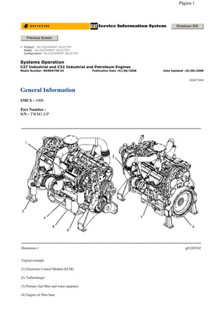
  • 1. Systems Operation C27 Industrial and C32 Industrial and Petroleum Engines General Information SMCS - 1000 Part Number - S/N - TWM1-UP Shutdown SIS Previous Screen Product: NO EQUIPMENT SELECTED Model: NO EQUIPMENT SELECTED Configuration: NO EQUIPMENT SELECTED Media Number -RENR9798-03 Publication Date -01/08/2008 Date Updated -26/08/2008 i03477244 Illustration 1 g01205382 Typical example (1) Electronic Control Module (ECM) (2) Turbocharger (3) Primary fuel filter and water separator (4) Engine oil filter base Página 1
  • 2. The Mechanical Electronic Unit Injector (MEUI) fuel system is used on this engine. The MEUI fuel system eliminates many of the mechanical components that are used in a pump and lines. The electronic control and mechanical actuation provides increased control of the timing and increased control of the fuel injection pressure. The timing advance is achieved by precise control of the unit injector timing. Engine speed is controlled by adjusting the injection duration. A special speed-timing wheel provides information to the Electronic Control Module (ECM) for detection of cylinder position and engine speed. The engine has built-in diagnostics in order to ensure that all of the components are operating properly. In the event of a system component failure, the operator will be alerted to the condition via the diagnostic lamp that is located on the control panel. Caterpillar Electronic Technician (ET) can be used to read the numerical code of the faulty component or condition. Intermittent faults are also logged and stored in memory. Starting the Engine The engine's ECM will automatically provide the correct amount of fuel in order to start the engine. Do not hold the throttle down while the engine is cranking. If the engine fails to start in twenty seconds, release the starting switch. Allow the starting motor to cool for two minutes before using the starting motor again. Cold Mode Operation The ECM will set the cold start strategy when the coolant temperature is below 20 °C (68 °F). When the cold start strategy is activated, low idle rpm will be increased and engine power will be limited. Cold mode operation will be deactivated when any of the following conditions have been met: Coolant temperature reaches 20 °C (68 °F). The engine has been running for twelve minutes. Cold mode operation uses a modified control map, that is stored in the ECM, in order to adjust the fuel injection timing and the injection duration for white smoke cleanup. The engine will usually exit the cold mode operation before the walk-around inspection is completed. During cold mode operation, the engine will remain at the elevated rpm that has been specified for the engine. After the cold mode is completed, the engine should be operated at low rpm until normal operating temperature is reached. The engine will reach normal operating temperature faster when the engine is operated at low rpm and low power demand. Customer Specified Parameters The engine is capable of being programmed for several customer specified parameters. For a brief explanation of each of the customer specified parameters, refer to the Operation and Maintenance Manual for your engine. (5) Engine oil filters (6) Secondary fuel filter and fuel priming pump (7) Exhaust manifold (8) Flywheel housing NOTICE Excessive ether (starting fluid) can cause piston and ring damage. Use ether for cold weather starting purposes only. Página 2
  • 3. Copyright 1993 - 2009 Caterpillar Inc. All Rights Reserved. Private Network For SIS Licensees. Mon Sep 14 11:48:13 EST 2009 Página 3
  • 4. Systems Operation C27 Industrial and C32 Industrial and Petroleum Engines General Information SMCS - 1000 Part Number - S/N - SMP1-UP Part Number - S/N - TLD1-UP Part Number - S/N - B2C1-UP Shutdown SIS Previous Screen Product: NO EQUIPMENT SELECTED Model: NO EQUIPMENT SELECTED Configuration: NO EQUIPMENT SELECTED Media Number -RENR9798-03 Publication Date -01/08/2008 Date Updated -26/08/2008 i02428487 Página 4
  • 5. The Mechanical Electronic Unit Injector (MEUI) fuel system eliminates many of the mechanical components that are used in a pump-and-line system. The electronic control and mechanical actuation also provide increased control of the timing and increased control of the fuel injection pressure. The timing advance is achieved by precise control of the unit injector timing. Engine speed is controlled by adjusting the injection duration. A special speed-timing wheel provides information to the Electronic Control Module (ECM) for Illustration 1 g01164605 (1) Turbocharger (2) Exhaust outlet (3) Electronic Control Module (ECM) (4) Primary fuel filter and water separator (5) Secondary fuel filter and fuel priming pump (6) Engine oil filters (7) Oil pan (8) Flywheel housing (9) Exhaust manifold Página 5
  • 6. detection of cylinder position and engine speed. The engine has built-in diagnostics in order to ensure that all of the components are operating properly. In the event of a system component failure, the operator will be alerted to the condition via the diagnostic lamp that is located on the control panel. Caterpillar Electronic Technician (ET) can be used to read the numerical code of the faulty component or condition. Intermittent faults are also logged and stored in memory. Starting the Engine The engine's ECM will automatically provide the correct amount of fuel in order to start the engine. Do not hold the throttle down while the engine is cranking. If the engine fails to start in twenty seconds, release the starting switch. Allow the starting motor to cool for two minutes before using the starting motor again. Cold Mode Operation The ECM will set the cold start strategy when the coolant temperature is below 20 °C (68 °F). When the cold start strategy is activated, low idle rpm will be increased and engine power will be limited. Cold mode operation will be deactivated when any of the following conditions have been met: Coolant temperature reaches 20 °C (68 °F). The engine has been running for twelve minutes. Cold mode operation uses a modified control map, that is stored in the ECM, in order to adjust the fuel injection timing and the injection duration for white smoke cleanup. The engine will usually exit the cold mode operation before the walk-around inspection is completed. During cold mode operation, the engine will remain at the elevated rpm that has been specified for the engine. After the cold mode is completed, the engine should be operated at low rpm until normal operating temperature is reached. The engine will reach normal operating temperature faster when the engine is operated at low rpm and low power demand. Customer Specified Parameters The engine is capable of being programmed for several customer specified parameters. For a brief explanation of each of the customer specified parameters, refer to the Operation and Maintenance Manual for your engine. NOTICE Excessive ether (starting fluid) can cause piston and ring damage. Use ether for cold weather starting purposes only. Copyright 1993 - 2009 Caterpillar Inc. All Rights Reserved. Private Network For SIS Licensees. Mon Sep 14 11:50:22 EST 2009 Página 6
  • 7. Systems Operation C27 Industrial and C32 Industrial and Petroleum Engines Electronic Control System Components SMCS - 1900 Part Number - S/N - TWM1-UP Shutdown SIS Previous Screen Product: NO EQUIPMENT SELECTED Model: NO EQUIPMENT SELECTED Configuration: NO EQUIPMENT SELECTED Media Number -RENR9798-03 Publication Date -01/08/2008 Date Updated -26/08/2008 i03211762 Illustration 1 g01205842 Top view (1) Intake manifold air temperature sensor Página 7
  • 8. (2) Intake manifold pressure sensor (3) Coolant temperature sensor (4) Atmospheric pressure sensor (5) Secondary engine speed/timing sensor (6) Coolant level sensor (7) Oil pressure sensor (8) Electronic Control Module (ECM) Illustration 2 g01387178 Front view (9) Primary engine speed/timing sensor Página 8
  • 9. The electronic control system is integrally designed into the engine's fuel system and the engine's air inlet and exhaust system in order to electronically control the fuel delivery. The electronic control system provides better timing control and fuel air ratio control in comparison to conventional mechanical engines. Injection timing is achieved by the precise control of the fuel injectors. Engine speed is controlled by adjusting the injection duration. The Electronic Control Module (ECM) energizes the unit injector solenoids in order to start the injection of fuel. Also, the ECM de-energizes the unit injector solenoids in order to stop the injection of fuel. Refer to Systems Operation/Testing And Adjusting, "Fuel System" for a complete explanation of the fuel injection process. The engine uses the following three types of electronic components: Input component Control component Illustration 3 g01387177 Section A-A (10) Fuel pressure sensor (11) Fuel temperature sensor Página 9
  • 10. Output component An input component is one that sends an electrical signal to the ECM. The signal that is sent varies in either of the following ways: Voltage Frequency Pulse width The variation of the signal is in response to a change in some specific system of the engine. Some specific examples of an input component are the engine speed-timing sensors, and the coolant temperature sensor. The ECM interprets the signal from the input component as information about the condition, environment, or operation of the engine. An ECM receives the input signals from the input components. Electronic circuits inside the control component evaluate the signals from the input components. These electronic circuits also supply electrical energy to the output components of the system. The electrical energy that is supplied to the output components is based on predetermined combinations of input signal values. An output component is one that is operated by a control module. The output component receives electrical energy from the control group. The output component uses electrical energy to make an adjustment in one of the engine's systems. An output component may also provide information to the operator. As an example, a moving solenoid plunger will perform work. By performing work, the component has functioned in order to regulate the engine. As an example, a control panel light or an alarm will provide information to the operator of the engine. These electronic components provide the ability to electronically control the engine operation. Engines with electronic controls offer the following advantages: Improvement in performance Improvement in fuel consumption Reduction in emissions levels Various sensors feed data to the ECM. The following sensors are used by the ECM for data: Engine coolant temperature Engine oil pressure Atmospheric pressure Primary speed/timing sensor Secondary speed/timing sensor Intake manifold air pressure Intake manifold air temperature The ECM processes the data. Then, the ECM sends an electronic signal to the fuel injector. The signal will control the amount of fuel that is injected into the cylinder. This will optimize the efficiency and the performance of the engine. Página 10
  • 11. Data Link A data link is used for the following items: Communicate engine information. Communicate with Caterpillar Electronic Technician (ET). Calibrate the electronic engine control system. Troubleshoot the electronic engine control system. Program the electronic engine control system. The data link is used to communicate engine information to other electronic control systems. Also, the data link can interface with Cat ET. Cat ET can be used to program the customer specified parameters. The tool is plugged into the data link connector. This allows Cat ET to communicate with the ECM. Also, Cat ET can be used to display the real time values of all the information that is available on the data link. This will help diagnose engine problems. Electronic Control Module (ECM) The engine uses an ECM. The ECM is a microprocessor based device. The ECM is mounted on the top of the front valve cover on the left side of the engine. Illustration 4 g01381771 Electronic Control Module (ECM) Página 11
  • 12. The inputs and the outputs to the ECM are designed to withstand short circuits without damage to the control module. The electronic engine control system has the following features that are designed into the system. Resistance to radio frequency Resistance to electromagnetic interference The system has passed tests for interference by two-way radios and by switching noise. The ECM power supply provides electrical power to all engine mounted sensors and actuators. The following precautions have been designed into the ECM. Reverse voltage polarity protection Swings or surges of the voltage in the power system due to sudden alternator load The ECM also monitors all sensor inputs and the ECM provides the correct outputs in addition to acting as a power supply. Also, the ECM ensures the desired engine operation. The ECM is programmed with a selected factory engine rating. The ECM memory contains a personality module identification code. This code is used to avoid unauthorized tampering or switching of personality modules and other pertinent manufacturing information. The wiring harness provides communications to the following areas: ECM Various sensors Data link connector Engine connectors The ECM is programmed to perform the following functions: Diagnostic tests on all inputs Diagnostic tests on all outputs Identify a faulty circuit. Once a fault is detected, the fault can be displayed on a diagnostic lamp. The diagnostic code can be read by using Cat ET. A multimeter can be used to check most problems. Also, a multimeter can be used to troubleshoot most problems. The ECM will record most diagnostic codes that are generated during engine operation. These logged codes or intermittent codes can be read by Cat ET. Copyright 1993 - 2009 Caterpillar Inc. All Rights Reserved. Private Network For SIS Licensees. Mon Sep 14 11:52:03 EST 2009 Página 12
  • 13. Systems Operation C27 Industrial and C32 Industrial and Petroleum Engines Electronic Control System Components SMCS - 1900 Part Number - S/N - SMP1-UP Part Number - S/N - TLD1-UP Part Number - S/N - B2C1-UP Shutdown SIS Previous Screen Product: NO EQUIPMENT SELECTED Model: NO EQUIPMENT SELECTED Configuration: NO EQUIPMENT SELECTED Media Number -RENR9798-03 Publication Date -01/08/2008 Date Updated -26/08/2008 i03211767 Página 13
  • 14. Illustration 1 g01157677 Top view of engine (1) Intake manifold air temperature sensor (2) Intake manifold pressure sensor (3) Coolant temperature sensor (4) Atmospheric pressure sensor (5) Electronic Control Module (ECM) (6) Fuel pressure sensor (7) Fuel differential pressure switch (8) Fuel temperature sensor Página 14
  • 15. The electronic control system is integrally designed into the engine's fuel system and the engine's air inlet and exhaust system in order to electronically control the fuel delivery. The electronic control system provides better timing control and fuel air ratio control in comparison to conventional mechanical engines. Injection timing is achieved by the precise control of the fuel injectors. Engine speed is controlled by adjusting the injection duration. The Electronic Control Module (ECM) energizes the unit injector solenoids in order to start the injection of fuel. Also, the ECM de-energizes the unit injector solenoids in order to stop the injection of fuel. Refer to Systems Operation/Testing And Adjusting, "Fuel System" for a complete explanation of the fuel injection process. The engine uses the following three types of electronic components: Input component Illustration 2 g01157719 Front view (9) Engine oil pressure sensor (10) Secondary speed/timing sensor (11) Primary speed/timing sensor Página 15
  • 16. Control component Output component An input component is one that sends an electrical signal to the ECM. The signal that is sent varies in either of the following ways: Voltage Frequency Pulse width The variation of the signal is in response to a change in some specific system of the engine. Some specific examples of an input component are the engine speed-timing sensors, and the coolant temperature sensor. The ECM interprets the signal from the input component as information about the condition, environment, or operation of the engine. An ECM receives the input signals from the input components. Electronic circuits inside the control component evaluate the signals from the input components. These electronic circuits also supply electrical energy to the output components of the system. The electrical energy that is supplied to the output components is based on predetermined combinations of input signal values. An output component is one that is operated by a control module. The output component receives electrical energy from the control group. The output component uses electrical energy to make an adjustment in one of the engine's systems. An output component may also provide information to the operator. As an example, a moving solenoid plunger will perform work. By performing work, the component has functioned in order to regulate the engine. As an example, a control panel light or an alarm will provide information to the operator of the engine. These electronic components provide the ability to electronically control the engine operation. Engines with electronic controls offer the following advantages: Improvement in performance Improvement in fuel consumption Reduction in emissions levels Various sensors feed data to the ECM. The following sensors are used by the ECM for data: Engine coolant temperature Engine oil pressure Atmospheric pressure Primary speed/timing sensor Secondary speed/timing sensor Fuel temperature Fuel pressure Intake manifold air pressure Página 16
  • 17. Intake manifold air temperature The ECM processes the data. Then, the ECM sends an electronic signal to the fuel injector. The signal will control the amount of fuel that is injected into the cylinder. This will optimize the efficiency and the performance of the engine. Data Link A data link is used for the following items: Communicate engine information. Communicate with Caterpillar Electronic Technician (ET). Calibrate the electronic engine control system. Troubleshoot the electronic engine control system. Program the electronic engine control system. The data link is used to communicate engine information to other electronic control systems. Also, the data link can interface with Cat ET. Cat ET can be used to program the customer specified parameters. The tool is plugged into the data link connector. This allows Cat ET to communicate with the ECM. Also, Cat ET can be used to display the real time values of all the information that is available on the data link. This will help diagnose engine problems. Electronic Control Module (ECM) The engine uses an ECM. The ECM is a microprocessor based device. The ECM is mounted on the top of the front valve cover on the left side of the engine. The inputs and the outputs to the ECM are designed to withstand short circuits without damage to the control module. The electronic engine control system has the following features that are designed into the system. Illustration 3 g01118503 Electronic Control Module (ECM) Página 17
  • 18. Resistance to radio frequency Resistance to electromagnetic interference The system has passed tests for interference by two-way radios and by switching noise. The ECM power supply provides electrical power to all engine mounted sensors and actuators. The following precautions have been designed into the ECM. Reverse voltage polarity protection Swings or surges of the voltage in the power system due to sudden alternator load The ECM also monitors all sensor inputs and the ECM provides the correct outputs in addition to acting as a power supply. Also, the ECM ensures the desired engine operation. The ECM is programmed with a selected factory engine rating. The ECM memory contains a personality module identification code. This code is used to avoid unauthorized tampering or switching of personality modules and other pertinent manufacturing information. The wiring harness provides communications to the following areas: ECM Various sensors Data link connector Engine connectors The ECM is programmed to perform the following functions: Diagnostic tests on all inputs Diagnostic tests on all outputs Identify a faulty circuit. Once a fault is detected, the fault can be displayed on a diagnostic lamp. The diagnostic code can be read by using Cat ET. A multimeter can be used to check most problems. Also, a multimeter can be used to troubleshoot most problems. The ECM will record most diagnostic codes that are generated during engine operation. These logged codes or intermittent codes can be read by Cat ET. Copyright 1993 - 2009 Caterpillar Inc. All Rights Reserved. Private Network For SIS Licensees. Mon Sep 14 12:09:33 EST 2009 Página 18
  • 19. Systems Operation C27 Industrial and C32 Industrial and Petroleum Engines Fuel System SMCS - 1250 Shutdown SIS Previous Screen Product: NO EQUIPMENT SELECTED Model: NO EQUIPMENT SELECTED Configuration: NO EQUIPMENT SELECTED Media Number -RENR9798-03 Publication Date -01/08/2008 Date Updated -26/08/2008 i02776678 Illustration 1 g01155662 (1) Cylinder head (2) Unit injector (3) Fuel transfer pump (4) Secondary fuel filter and priming pump (5) Fuel tank (6) Electronic Control Module (ECM) (7) Primary fuel filter and water separator Página 19
  • 20. The fuel supply circuit is a conventional design for unit injector diesel engines. The system consists of the following major components that are used to deliver low pressure fuel to the unit injectors: Fuel tank - The fuel tank is used to store the fuel. Fuel priming pump - The fuel priming pump is used to evacuate the air from the fuel system. As the air is removed the system fills with fuel. Fuel filters - The primary fuel filter is used to remove abrasive material and contamination from the fuel system that may be large enough to damage the fuel transfer pump. The secondary fuel filter is used to remove abrasive material and contamination as small as two microns that could damage the injectors. Supply lines and return lines - Supply lines and return lines are used to deliver the fuel to the different components. The purpose of the low pressure fuel supply circuit is to supply fuel that has been filtered to the fuel injectors at a rate that is constant and a pressure that is constant. The fuel system is also utilized to cool components such as the fuel injectors and the Electronic Control Module (ECM). Once the injectors receive the low pressure fuel, the fuel is pressurized again before the fuel is injected into the cylinder. The unit injector uses mechanical energy that is provided by the camshaft to achieve pressures that can be in excess of 200000 kPa (30000 psi). Control of the fuel delivery is managed by the engine's ECM. Data from several of the engine systems is collected by the ECM and processed in order to manage these aspects of fuel injection control: Injection timing Fuel injection timing advance Injection duration Engine cold mode status The mechanical electronic fuel system relies on a large amount of data from the other engine systems. The data that is collected by the ECM will be used in order to provide optimum performance of the engine. Low Pressure Fuel Supply Circuit The flow of fuel through the system begins at fuel tank (5) . Fuel is drawn through the primary fuel filter and water separator (7) from the fuel tank by fuel transfer pump (3) . The fuel transfer pump incorporates a check valve that will allow fuel to flow around the gears of the pump during priming of the fuel system. The fuel transfer pump also incorporates a pressure relief valve. The pressure relief valve is used in order to protect the fuel system from extreme pressure. The fuel transfer pump is designed in order to produce an excess fuel flow throughout the fuel system. The excess fuel flow is used by the system to cool the fuel system components. The excess fuel flow also purges any air from the fuel system during operation. Air that can become trapped in the fuel system can cause cavitation that may damage the components of the unit injector. After leaving the fuel transfer pump, the fuel flows to the ECM (6) in order to cool the ECM. Next, the fuel flows to the secondary fuel filter and fuel priming pump (4) . The fuel priming pump is located on the fuel filter base. The fuel filter base and the secondary fuel filter also incorporate a siphon break that prevents fuel from draining from the fuel system when the engine is not in operation. The priming pump is a hand operated pump that directs the flow of fuel during the priming pump's operation. The secondary fuel filter is a two micron fuel filter. The fuel is filtered in order to remove small abrasive particles that will cause premature wear to fuel system components. The filtered fuel then flows out of the fuel filter and returns to the passages in the fuel filter base. Prior to exiting the fuel filter base, the fuel pressure and the fuel temperature are sampled by the fuel pressure sensor and by the fuel temperature sensor. The signals that are generated by the sensors are Página 20
  • 21. used by the ECM in order to monitor the condition of the engine's components. This information is also used to adjust the fuel delivery of the engine in order to optimize efficiency. The fuel is then transfered by the fuel supply lines to the cylinder head (1) . Only a portion of the fuel that is supplied to the fuel injectors is used for engine operation. This unused fuel is discharged into the return passages of the fuel gallery. The fuel is returned to the fuel tank by the fuel return lines. A continuous flow of fuel is experienced within the low pressure fuel system. During engine operation, fuel injectors (2) receive fuel from the low pressure fuel system. The injector pressurizes the fuel to high pressure. The fuel is then injected into the cylinder. The excess fuel is returned to the tank. A pressure regulating valve is located in the fuel return. The pressure regulating valve allows the low pressure fuel system to maintain a constant pressure. A flow control orifice is also located in the fuel return. The flow control orifice maintains a system back pressure that is constant. The orifice allows the flow of fuel through the system to be constant. This prevents excessive heating of the fuel. Fuel Heaters Fuel heaters prevent the waxing of the fuel, and the plugging of the fuel filters in cold weather. The engine does not dissipate enough heat in order to prevent waxing during cold weather conditions. There are two types of fuel heaters that can be used: thermostatically controlled and self-adjusting. Heaters that are not thermostatically controlled can heat the fuel in excess of 65 °C (149 °F). High fuel temperatures can have the following effects: Reduced engine efficiency Fuel pump damage Premature wear Note: Never use fuel heaters without some type of temperature regulator. Ensure that fuel heaters are turned OFF during warm weather conditions. Fuel System Electronic Control Circuit The fuel system is equipped with an electronically controlled, mechanically actuated unit injector in each cylinder. A solenoid on each injector controls the amount of fuel that is delivered by the injector. An ECM sends a signal to each injector solenoid in order to provide complete control of the engine. There are two major components of the electronic control system that are necessary in order to provide control of the mechanical electronic unit injectors: ECM Personality module (storage for the ECM flash file) The ECM is the computer that is used to provide control for all aspects of engine operation. The personality module contains the software that defines the characteristics of the engine control. The personality module contains the operating maps. The operating maps define the following characteristics of the engine: Horsepower Torque curves Engine speed (rpm) Other characteristics Página 21
  • 22. The ECM, the personality module, the engine sensors, and the unit injectors work together in order to control the engine. Neither of the four can control the engine alone. The ECM maintains the desired engine speed by sensing the actual engine speed. The ECM calculates the amount of fuel that needs to be injected in order to achieve the desired engine speed. Fuel Injection The ECM controls the amount of fuel that is injected by varying the signals that are sent to the injectors. The ECM sends a high voltage signal to the solenoid in order to energize the solenoid. The injectors will inject fuel only while the injector solenoid is energized. By controlling the timing and the duration of the high voltage signal, the ECM can control injection timing and the amount of fuel that is injected. The ECM sets certain limits on the amount of fuel that can be injected. The Fuel Ratio Control (FRC) limit is an adjustment that controls the amount of air and the amount of fuel for the purpose of emission control. This limit is based on the boost pressure. When the ECM senses a higher boost pressure, the ECM increases the FRC limit. The rated fuel position is also a limit that is based on the horsepower rating of the engine. This is similar to the rack stops and to the torque spring on a mechanically governed engine. The rated fuel position provides horsepower and torque curves for a specific engine family and for a specific engine rating. All of these limits are programmed into the personality module by the factory. These limits are not programmable by the service technician. Injection timing depends on three factors: the engine speed (rpm), the engine load and the operational conditions of the engine. The ECM determines the top center position of No. 1 cylinder from the signal that is provided by the engine speed/timing sensor. The ECM decides when the injection should occur relative to the top center position. The ECM then provides the signal to the electronic unit injector at the desired time. Electronic Unit Injector Mechanism Página 22
  • 23. The electronic unit injector mechanism provides the downward force that is required to pressurize the fuel in the electronic unit injector pump. The electronic unit injector (7) allows fuel to be injected into the combustion chamber with precise timing. Movement is transmitted from the camshaft lobe (10) for the electronic unit injector through the rocker arm assembly (9) to the top of the electronic unit injector. The adjusting nut (8) allows the injector lash to be adjusted. For the proper setting of the injector lash, refer to the topic on adjustment of the electronic unit injector in Testing and Adjusting, "Electronic Unit Injector - Adjust". Electronic Unit Injector Illustration 2 g01387534 Electronic unit injector mechanism (7) Electronic unit injector (8) Adjusting nut (9) Rocker arm assembly (10) Camshaft lobe Illustration 3 g01387536 Electronic unit injector (11) Spring (12) Solenoid connection to the Electronic Control Module (ECM) (13) Solenoid valve assembly Página 23
  • 24. Fuel at low pressure from the fuel supply manifold enters the electronic unit injector at the fill port through drilled passages in the cylinder head. As the electronic unit injector mechanism transfers the force to the top of the electronic unit injector, spring (11) is compressed and plunger (14) is driven downward. This action displaces fuel through the valve in solenoid valve assembly (13) , and into the return manifold to the fuel tank. As the plunger travels downward, the passage in barrel (15) is closed by the outside diameter of the plunger. The passages within body (20) and along check valve (21) to the injector tip already contain fuel for injection. After the passage in the plunger barrel is closed, the injector is ready for injection at any time. The start of injection relies on the software in the Electronic Control Module (ECM). When the solenoid valve assembly is energized from a signal across solenoid connection (12) , the valve closes and fuel pressure is elevated in the injector tip. Injection begins at 34500 ± 1900 kPa (5000 ± 275 psi) as the force of spring (18) above spacer (19) is overcome. The check valve begins to lift from the valve seat. The pressure continues to rise as the plunger cycles through a full stroke. After the correct amount of fuel has been discharged into the cylinder, the ECM removes the signal to the solenoid connection. The solenoid valve assembly is de-energized and the valve in the solenoid valve assembly is opened. The high pressure fuel is then dumped through the spill port and into the fuel return manifold. The fuel is then returned to the fuel tank. The check valve in the injector tip seats as the pressure in the tip decreases. The duration of injection meters the fuel that is consumed during the fuel injection process. Injection duration is controlled by the governor logic that is programmed into the ECM. As the camshaft lobe rotates past the point of maximum lobe lift, the force on top of the electronic unit injector is removed and the spring for the injector mechanism is allowed to expand. The plunger returns to the original position. This uncovers the fuel supply passage into the plunger barrel in order to refill the injector pump body. The fuel at low pressure is again allowed to circulate through the fuel injector body. After circulating through the fuel injector body, the fuel flows out of the spill port. This continues until the solenoid valve assembly is re-energized for another injection cycle. (14) Plunger assembly (15) Barrel (16) Seal (17) Seal (18) Spring (19) Spacer (20) Body (21) Check valve Copyright 1993 - 2009 Caterpillar Inc. All Rights Reserved. Private Network For SIS Licensees. Mon Sep 14 13:17:50 EST 2009 Página 24
  • 25. Systems Operation C27 Industrial and C32 Industrial and Petroleum Engines Air Inlet and Exhaust System SMCS - 1050 The air inlet and the exhaust system includes the following components: Turbocharger Exhaust manifold Exhaust valves Inlet valves Cylinder head Valve system components Shutdown SIS Previous Screen Product: NO EQUIPMENT SELECTED Model: NO EQUIPMENT SELECTED Configuration: NO EQUIPMENT SELECTED Media Number -RENR9798-03 Publication Date -01/08/2008 Date Updated -26/08/2008 i03211775 Página 25
  • 26. The engine is set up for an air-to-air aftercooled arrangement. In an air-to-air aftercooled arrangement, clean inlet air from an air cleaner is pulled through the air inlet of the turbochargers by the turning of compressor wheel. The compressor wheel causes a compression of the air. The turbochargers compress the inlet air so that a larger volume of air can be drawn into the cylinders. This compressing of the inlet air is referred to as boost. The compression of the inlet air causes the temperature of the air to increase. The air then flows to an aftercooler. An aftercooler will cool the inlet air. Cooling of the inlet air causes the air to become more dense. This increases the combustion efficiency and the horsepower output of the engine. The air then flows from the aftercooler to the inlet manifolds of the engine. When the inlet valves open, the air flows into the Illustration 1 g01155724 Typical Example (1) Turbochargers (2) Exhaust outlets (3) Inlet manifolds (4) Exhaust manifolds (5) Exhaust valves (6) Inlet valves Página 26
  • 27. engine cylinders. The air is mixed with the fuel for combustion. When the exhaust valves open, the exhaust gases go out of the engine cylinders and into exhaust manifolds. From the exhaust manifolds, the exhaust gases flow through the blades of the turbine wheel in the turbochargers. This causes the turbine wheel to spin. The exhaust gases then flow out of the exhaust outlet of the turbocharger. Turbocharger Illustration 2 g01388253 Turbocharger (7) Air inlet (8) Compressor housing (9) Compressor wheel (10) Bearing (11) Oil Inlet port (12) Bearing (13) Turbine housing (14) Turbine wheel (15) Exhaust outlet (16) Oil outlet port Página 27
  • 28. All of the air that enters the engine passes through the turbocharger. All of the exhaust gases from the engine pass through the turbocharger. The exhaust gases enter turbine housing (13) through exhaust inlet (17). The exhaust gas pushes on the blades of the turbine wheel (14). The turbine wheel is connected by a shaft to the compressor wheel (9) . Air that passes through the air filters enters the compressor housing air inlet (7) by the rotation of compressor wheel (9). The compressor wheel causes the inlet air to be pushed into the inlet side of the engine. Boost pressure is caused when the compressor wheel pushes more air into the inlet side of the engine. This results in an inlet manifold pressure that exceeds atmospheric pressure. This allows the engine to burn more fuel. When the engine burns more fuel the engine produces more power. When the throttle is opened, more fuel is injected into the cylinders. The combustion of this additional fuel produces greater exhaust temperature. The additional exhaust temperature causes the turbine and the compressor wheels of the turbocharger to turn faster. As the compressor wheel turns faster, more air is forced into the cylinders. The increased flow of air gives the engine more power by allowing the engine to burn the additional fuel with greater efficiency. Bearings (10) and (12) for the turbocharger use engine oil under pressure for lubrication and cooling. The oil comes in through oil inlet port (11). The oil then goes through passages in the center section in order to lubricate the bearings. This oil also cools the bearings. Oil from the turbocharger goes out through oil outlet port (16) in the bottom of the center section. The oil then goes back to the engine oil pan. Valve System Components (17) Exhaust inlet Página 28
  • 29. The valve train controls the flow of inlet air and exhaust gases into the cylinders and out of the cylinders during engine operation. The camshaft (21) controls the timing of the valves during engine operation. The crankshaft gear drives the camshaft gear through an idler gear. The camshaft must be timed to the crankshaft in order to get the correct relation between the piston position and the valve position. The camshaft has three camshaft lobes for each cylinder. One camshaft lobe operates the inlet valves. One camshaft lobe operates the exhaust valves. One camshaft lobe operates the unit injector. The camshaft lobes cause the follower on the rocker arm to actuate the valves and the unit injector. Each cylinder has two inlet valves and two exhaust valves. Valve springs hold the valves closed and the valve springs resist the opening of the valves. This ensures that the valves will close at high rpm and under high boost pressures. Valve rotators cause the valves to rotate while the engine is running. The rotation of the valves prevents the valves from burning by constantly changing the contact area of the valve face and the valve seat. This rotation gives the valves longer service life. Illustration 3 g01388254 Valve system components (18) Rocker arm (19) Locknut (20) Rocker arm shaft (21) Camshaft (22) Valve bridge Copyright 1993 - 2009 Caterpillar Inc. All Rights Reserved. Private Network For SIS Licensees. Mon Sep 14 13:20:13 EST 2009 Página 29
  • 30. Systems Operation C27 Industrial and C32 Industrial and Petroleum Engines Lubrication System SMCS - 1300 Lubrication System Components The lubrication system has the following components: Oil pan Oil pump Oil cooler Oil filter Turbocharger oil lines Oil passages for the cylinder block Oil Flow Through the Oil Filter and Oil Cooler Shutdown SIS Previous Screen Product: NO EQUIPMENT SELECTED Model: NO EQUIPMENT SELECTED Configuration: NO EQUIPMENT SELECTED Media Number -RENR9798-03 Publication Date -01/08/2008 Date Updated -26/08/2008 i03211779 Página 30
  • 31. When the engine is warm, oil is drawn from the oil pan (6) through the suction lines (9) to the oil pump (7). The oil pump pushes the hot oil through the oil cooler (11). The oil is then sent to the oil filter (4). Oil from the oil filter is sent to the oil manifold (1) in the cylinder block and to the oil supply line (2) for the turbocharger. Oil from the turbocharger goes back through the oil return line (3) to the oil pan. When the engine is cold, oil is drawn from the oil pan (6) through the suction lines (9) to the oil pump (7). When the oil is cold, an oil pressure differential in the bypass valves causes the bypass valves to open. These bypass valves then provide immediate lubrication to all of the engine components when cold oil with high viscosity causes a restriction to oil flow through the oil cooler (11) and the oil filter (4). The oil pump then pushes the cold oil through the bypass valve (8) for the oil cooler and through the bypass valve (5) for the oil Illustration 1 g01241567 (1) Oil manifold (2) Oil supply line (3) Oil return line (4) Oil filter (5) Bypass valve for the oil filter (6) Oil pan (7) Oil pump (8) Bypass valve for the oil cooler (9) Suction lines (10) Bypass valve for the oil pump (11) Oil cooler Página 31
  • 32. filter. The oil then goes to the oil manifold (1) in the cylinder block and to the supply line (2) for the turbocharger. Oil from the turbocharger goes back through the oil return line (3) to the oil pan. When the oil is warm, an oil pressure differential in the bypass valves causes the bypass valves to close. This differential continues the normal flow of oil through the oil cooler and the oil filter. The bypass valves will also open when there is a restriction in the oil cooler or the oil filter. This prevents a restricted oil filter or a restricted oil cooler from stopping the lubrication of the engine. The system pressure is limited by the oil pump bypass valve (10) . Oil Flow In The Engine Illustration 2 g01241572 Engine oil flow schematic (12) Camshaft bearing journals (13) Rocker arm shaft (14) Oil passage to adjustable idler gear (15) Oil passage to air compressor (16) Oil passage to the fixed idler stub shaft (17) Piston cooling jet (18) Oil passage to cluster idler gear (19) Crankshaft main bearings (20) Oil passage from filter Página 32
  • 33. The oil from the oil manifold (21) is sent under pressure through drilled passages to the crankshaft main bearings (19). The oil flows through drilled holes in the crankshaft. This oil lubricates the connecting rod bearings. A small amount of oil is sent to the piston cooling jets (17). The piston cooling jets spray oil on the underside of the pistons. Oil flows through passages in the timing gear housing and the accessory drive gear. This oil flows to the air compressor through the oil passage (15) . Oil passage (14) provides oil to the adjustable idler gear. Oil passage (16) provides oil to the fixed idler gear. Oil passage (18) provides oil to the cluster gear. The oil flows through a passage in the shafts of the gears. There is a pressure control valve in the oil pump. This valve controls the pressure of the oil that flows from the oil pump. Oil passage (19) provides lubrication to the rear crankshaft seal. This ensures a long service life for the rear crankshaft seal. Oil flows into the cylinder head via a hollow locating dowel in the top deck of the cylinder block. Oil travels to the camshaft bearing journals (12) and the three center rocker arm shaft supports through drilled passages in the cylinder head. The supports supply oil to each rocker shaft. Oil flows to the bushings of the fuel injector rocker arm through holes in the rocker arm shaft (13). This same oil lubricates the valve and the rollers. Oil flows through drilled passages in the rocker arms. This oil lubricates the roller, the valve bridge and the contact surfaces of the actuator of the unit injector. Splash oil lubrication is used to lubricate other components of the valve system. Excess oil returns to the engine oil pan. (21) Oil manifold Copyright 1993 - 2009 Caterpillar Inc. All Rights Reserved. Private Network For SIS Licensees. Mon Sep 14 13:22:47 EST 2009 Página 33
  • 34. Systems Operation C27 Industrial and C32 Industrial and Petroleum Engines Cooling System SMCS - 1350 This engine has a pressure type cooling system that is equipped with a shunt line. A pressure type cooling system offers two advantages: The cooling system can operate safely at a temperature that is higher than the normal boiling point of water. The cooling system prevents cavitation in the water pump. Cavitation is the sudden formation of low pressure bubbles in liquids by mechanical forces. The formation of air or steam pockets is more difficult within a pressure type cooling system. The shunt line prevents cavitation by the water pump. The shunt line provides a constant head pressure at the water pump inlet. Note: The coolant mixture must be a minimum of 30 percent ethylene glycol base antifreeze for efficient water pump performance for air to air after cooled engines. The mixture keeps the cavitation temperature range of the coolant high enough for efficient performance. Shutdown SIS Previous Screen Product: NO EQUIPMENT SELECTED Model: NO EQUIPMENT SELECTED Configuration: NO EQUIPMENT SELECTED Media Number -RENR9798-03 Publication Date -01/08/2008 Date Updated -26/08/2008 i02307552 Página 34
  • 35. Water pump (9) is located on the right side of the cylinder block. The water pump is gear-driven from the front gear group. Coolant can enter the water pump in two places: Inlet at the bottom of the water pump Bypass hose (4) at the top of the water pump Coolant from the bottom of the radiator (5) is pulled into the bottom inlet of the water pump (9) by impeller rotation. The coolant exits the back of the pump directly into engine oil cooler (7). Some of the coolant is also diverted to transmission oil cooler (8) (if equipped). Some of the coolant passes through the core of engine oil cooler (7) and some of the coolant passes through the core of transmission oil cooler (8) (if equipped). The coolant then enters the internal water manifold of the cylinder block. The manifold disperses the coolant to water jackets around the cylinder walls. From the cylinder block, the coolant flows into passages in the cylinder heads. The passages send the flow around the unit injector sleeves and the inlet and the exhaust passages. The coolant now enters water temperature regulator housing (2) at the front of the cylinder head. Illustration 1 g01155880 (1) Cylinder head (2) Water temperature regulator housing (3) Expansion tank (4) Bypass hose (5) Radiator (6) Cylinder block (7) Engine oil cooler (8) Transmission oil cooler (if equipped) (9) Water pump Página 35
  • 36. Two water temperature regulators control the direction of coolant flow. When the coolant temperature is below the normal operating temperature, the water temperature regulators are closed. The coolant is directed through bypass hose (4) and into the top inlet of the water pump. When the coolant temperature reaches the normal operating temperature, the water temperature regulators open. When the water temperature regulators are open, the bypass is closed. Most of the coolant goes through the outlet to the radiator for cooling. The remainder flows through bypass hose (4) and into the water pump. Note: The water temperature regulators are an important part of the cooling system. The water temperature regulators divide coolant flow between the radiator and the bypass hose in order to maintain the normal operating temperature. If the water temperature regulators are not installed in the system, there is no mechanical control, and most of the coolant will travel the path of least resistance through the bypass hose. This will cause the engine to overheat in hot weather and the engine will not reach normal operating temperature in cold weather. Coolant Conditioner (If Equipped) Some conditions of operation can cause pitting. This pitting is caused by corrosion or by cavitation erosion. A corrosion inhibitor is a chemical that provides a reduction in pitting. The addition of a corrosion inhibitor can keep this type of damage to a minimum. Illustration 2 g01155995 (2) Water temperature regulator housing (4) Bypass hose (9) Water pump (10) Outlet to the radiator (11) Inlet from the radiator Página 36
  • 37. The coolant conditioner element is a spin-on element that is similar to the fuel filter and to the oil filter elements. The coolant conditioner element attaches to the coolant conditioner base that is mounted on the front of the engine. Coolant flows from the water pump to the coolant conditioner base and back to the cylinder block. Coolant constantly flows through the coolant conditioner element when the valves are in the OPEN position. The element has a specific amount of inhibitor for acceptable cooling system protection. As the coolant flows through the element, the corrosion inhibitor goes into the solution. The corrosion inhibitor is a dry solution, so the inhibitor dissolves. The corrosion inhibitor then mixes to the correct concentration. Two basic types of elements are used for the cooling system. The two elements are the precharge elements and the maintenance elements. Each type of element has a specific use. The elements must be used correctly in order to get the necessary concentration for cooling system protection. The elements also contain a filter. The coolant conditioner elements should remain in the system after the conditioner material has dissolved. The precharge element contains more than the normal amount of inhibitor. The precharge element is used when a system is first filled with new coolant. This element must add enough inhibitor in order to bring the complete cooling system up to the correct concentration. The maintenance elements have a normal amount of inhibitor. The maintenance elements are installed at the first change interval. A sufficient amount of inhibitor is provided by the maintenance elements in order to maintain the corrosion protection at an acceptable level. After the first change interval, only maintenance elements are installed. In order to provide the cooling system with protection, maintenance elements are installed at specific intervals. Copyright 1993 - 2009 Caterpillar Inc. All Rights Reserved. Private Network For SIS Licensees. Mon Sep 14 13:25:42 EST 2009 Página 37
  • 38. Systems Operation C27 Industrial and C32 Industrial and Petroleum Engines Basic Engine SMCS - 1200 Cylinder Block Assembly The cylinders in the left side of the block form a 65 degree angle with the cylinders in the right side. The main bearing caps are fastened to the block with four bolts, two bolts through each bearing cap and two bolts through the side of the block. The cylinder liners can be removed for replacement. The top surface of the block is the seat for the cylinder liner flange. Engine coolant flows around the liners in order to keep the liners cool. Three O-ring seals around the bottom of the liner make a seal between the liner and the cylinder block. A filler band goes under the liner flange. This makes a seal between the top of the liner and the cylinder block. A steel spacer plate is used between the cylinder head and the block. The spacer plate provides improved reusability and durability. A thin gasket is used between the plate and the block. This thin gasket seals water and oil. A thick gasket of metal and graphite is used between the plate and the head. This thick gasket seals the combustion gases, water and oil. Cylinder Head Assembly The cylinder heads are a one-piece cast iron head. The cylinder head supports the camshaft. Steel reinforced camshaft bearings are pressed into each bore for the camshaft. The bearings are lubricated under pressure. The cylinder head contains two inlet valves and two exhaust valves for each cylinder, which are controlled by the rotation of the camshaft. Bridge dowels have been eliminated as the valve train uses floating valve bridges. The unit injector is mounted in a stainless steel adapter. This adapter has been pressed into the cylinder head injector bore. Pistons, Rings And Connecting Rods The piston is a one-piece design that consists of a forged steel crown and a skirt. The piston is retained by the piston pin to the small end of the connecting rod. The pistons have three rings that are located in grooves in the steel crown. These rings seal the combustion gas. The rings provide control of the oil. The top ring has a barrel face. This ring is a Keystone ring with a plasma face coating. The second ring has a tapered face and the ring has a coating of chrome finish for the face. The third ring is the oil ring. The third ring has a coil spring expander. There are four holes that are drilled from the piston oil ring groove to the interior of the piston. These holes return excess oil from the oil ring groove to the crankcase. The connecting rod is a conventional design. The cap of the connecting rod is attached to the shank by four bolts that are threaded into the shank. Each side of the small end of the connecting rod is machined at an Shutdown SIS Previous Screen Product: NO EQUIPMENT SELECTED Model: NO EQUIPMENT SELECTED Configuration: NO EQUIPMENT SELECTED Media Number -RENR9798-03 Publication Date -01/08/2008 Date Updated -26/08/2008 i03211788 Página 38
  • 39. angle of 12 degrees in order to fit within the piston cavity. Crankshaft The crankshaft converts the combustion force in the cylinder into rotating torque. A vibration damper is used at the front of the crankshaft in order to reduce the torsional vibrations. The crankshaft drives a group of gears on the front and the rear of the engine. These gear trains provide power for the following components: camshaft, water pump, oil pump, fuel transfer pump and accessory items that are specific to the application. The cylinder block has seven main bearings that support the crankshaft. The cylinder block uses four bolts to hold each of the bearing caps into the block. Pressurized oil is supplied to all bearing surfaces through drilled holes in the webs of the cylinder block. The oil then flows through drilled holes in the crankshaft in order to provide oil to the connecting rod bearings. Seals and wear sleeves are used at both ends of the crankshaft. The seals and wear sleeves are used for easy replacement and reduction of maintenance cost. Camshaft The camshaft has three lobes at each cylinder. These lobes allow the camshaft to operate the unit injector, the exhaust valves, and the inlet valves. The camshaft is supported in the cylinder head by seven journals which are fit with bearings. The camshaft gear contains integral roller dampers that counteract the torsional vibrations that are generated by the high fuel pressure during fuel injector operation. The design reduces gear train noise. The camshaft is driven by an adjustable idler gear which is turned by a fixed idler gear which is turned by a cluster idler gear in the gear train. Each bearing journal is lubricated from the oil manifold in the cylinder head. A thrust plate that is located at the front controls the end play of the camshaft. Timing of the camshaft is accomplished by aligning marks on the crankshaft gear and idler gear, and camshaft gear with a mark on the front timing plate. Vibration Damper The twisting of the crankshaft is called torsional vibration. The torsional vibration is caused by the regular power impacts along the length of the crankshaft. The vibration damper is installed on the front end of the crankshaft. This vibration damper is used to reduce the torsional vibrations. This eliminates any damage that could occur to the crankshaft. The rubber damper is made of an outer hub connected to an inner hub by a rubber ring. The rubber makes a flexible coupling between the outer hub and the inner hub. The viscous damper consists of a casing that is welded to the inner hub. The casing contains a steel weight that is suspended in a viscous silicone lubricant. The silicone lubricant acts as a flexible coupling between the weight and the inner hub. Copyright 1993 - 2009 Caterpillar Inc. All Rights Reserved. Private Network For SIS Licensees. Mon Sep 14 13:27:18 EST 2009 Página 39
  • 40. Systems Operation C27 Industrial and C32 Industrial and Petroleum Engines Electrical System SMCS - 1400; 1550; 1900 Reference Refer to the Schematic and the Troubleshooting, "Electronic Troubleshooting" for additional information on your engine. Grounding Practices Proper grounding for the electrical system is necessary for proper engine performance and reliability. Improper grounding will result in unreliable electrical circuit paths and in uncontrolled electrical circuit paths. Uncontrolled engine electrical circuit paths can result in damage to the main bearings, to the crankshaft bearing journal surfaces, and to the aluminum components. Uncontrolled electrical circuit paths can cause electrical noise which may degrade performance. In order to ensure proper functioning of the electrical system, an engine-to-frame ground strap with a direct path to the battery must be used. This may be provided by a ground for the starting motor, by a frame to the ground for the starting motor, or by a direct frame to engine ground. An engine-to-frame ground strap must be run from the grounding stud of the engine to the frame and to the negative battery post. Connect the battery negative post to the frame rail. From the frame rail, connect the ground wire to one of the following locations: Cylinder head ground stud Optional engine ground stud connection The engine must be grounded to the frame rail. Connect the battery negative post to one of the following locations: Cylinder head ground stud Optional engine ground stud connection The engine must have a ground wire to the battery. Ground wires or ground straps should be combined at the studs that are only for ground use. Shutdown SIS Previous Screen Product: NO EQUIPMENT SELECTED Model: NO EQUIPMENT SELECTED Configuration: NO EQUIPMENT SELECTED Media Number -RENR9798-03 Publication Date -01/08/2008 Date Updated -26/08/2008 i02770527 Página 40
  • 41. All of the ground paths must be capable of carrying any potential currents. The engine alternator should be grounded to the battery with a wire size that is capable of managing the full charging current of the alternator. The engine has several input components which are electronic. These components require an operating voltage. This engine is tolerant to common external sources of electrical noise. Electromechanical buzzers can cause disruptions in the power supply. If electromechanical buzzers are used near the system, the engine electronics should be powered directly from the battery system through a dedicated relay. The engine electronics should not be powered through a common power bus with other devices that are activated by the Engine Control Switch (ECS). Engine Electrical System The electrical system can have three separate circuits. The three circuits are the charging circuit, the starting circuit, and the low amperage circuit. Some of the electrical system components are used in more than one circuit. The charging circuit is in operation when the engine is running. An alternator creates electricity for the charging circuit. A voltage regulator in the circuit controls the electrical output in order to maintain the battery at full charge. The starting circuit is in operation when the start switch is activated. The low amperage circuit and the charging circuit are connected through the ammeter. The starting circuit is not connected through the ammeter. Charging System Components Alternator The alternator is driven by the crankshaft pulley through a belt that is a Poly-vee type. This alternator is a three-phase self-rectifying charging unit. The regulator is part of the alternator. The alternator design has no need for slip rings or for brushes. The only part of this alternator that moves is the rotor assembly. All of the conductors that carry current are stationary. The following components are the conductors: the field winding, the stator windings, six rectifying diodes and the regulator circuit. The rotor assembly has many magnetic poles with air space between each of the opposite poles. The poles have residual magnetism that produces a small amount of magnet-like lines of force (magnetic field). This magnetic field is produced between the poles. As the rotor assembly begins to turn between the field winding and the stator windings, a small amount of Alternating Current (AC) is produced in the stator NOTICE When jump starting an engine, the instructions in the Operation and Maintenance Manual, "Starting with Jump Start Cables" should be followed in order to properly start the engine. This engine may be equipped with a 12 volt starting system or with a 24 volt starting system. Only equal voltage for boost starting should be used. The use of a welder or of a higher voltage will damage the electrical system. Página 41
  • 42. windings. The alternating current is produced from the small magnetic lines of force that are created by the residual magnetism of the poles. The AC is changed into Direct Current (DC) when the current passes through the diodes of the rectifier bridge. Most of this current provides the battery charge and the supply for the low amperage circuit. The remainder of current is sent to the field windings. The DC current flow through the field windings (wires around an iron core) increases the strength of the magnetic lines of force. These stronger magnetic lines of force increase the amount of AC that is produced in the stator windings. The increased speed of the rotor assembly also increases the current output of the alternator and the voltage output of the alternator. The voltage regulator is a solid-state electronic switch. The voltage regulator senses the voltage of the system. The regulator then uses switches to control the current to the field windings. This controls the voltage output in order to meet the electrical demand of the system. NOTICE The alternator should never be operated without the battery in the circuit. The making or the breaking of an alternator connection with a heavy load on the circuit can cause damage to the regulator. Illustration 1 g01096944 Typical cross section of an alternator (1) Regulator (2) Roller bearing (3) Stator winding (4) Ball bearing (5) Rectifier bridge (6) Field winding (7) Rotor assembly (8) Fan Página 42
  • 43. Starting System Components Solenoid A solenoid is an electromagnetic switch that performs two basic functions: The solenoid closes the high current circuit for the starting motor with a low current start switch circuit. The solenoid engages the pinion for the starting motor with the ring gear. The solenoid has windings (one set or two sets) around a hollow cylinder or a hollow housing. A plunger that is spring loaded is located within the solenoid housing. The plunger can move forward and backward. When the start switch is closed and electricity is sent through the windings, a magnetic field is created. The magnetic field pulls the plunger forward in the solenoid housing. This moves the shift lever in order for the pinion drive gear to engage with the ring gear. The front end of the plunger then makes contact across the battery and across the motor terminals of the solenoid. The starting motor then begins to turn the flywheel of the engine. When the start switch is opened, current no longer flows through the windings. The spring now returns the plunger to the original position. At the same time, the spring moves the pinion gear away from the flywheel. When two sets of windings in the solenoid are used, the windings are called the hold-in winding and the pull-in winding. Both of the windings wind around the cylinder for an equal amount of times. The pull-in winding uses a wire with a larger diameter in order to produce a stronger magnetic field. When the start switch is closed, part of the current flows from the battery through the hold-in winding. The remainder of the current flows through the pull-in windings, to the motor terminal, and then to the ground. When the solenoid is activated, the current is shut off through the pull-in windings. Only the smaller hold-in windings are in operation for the extended period of time that is necessary for the engine to be started. The solenoid will now take a smaller amount of current from the battery. Heat that is created by the solenoid will be kept at an acceptable level. Starting Motor Illustration 2 g00292316 Typical cross section of a solenoid Página 43
  • 44. The starting motor rotates the engine flywheel at a rate that is fast enough to start the engine. The starting motor has a solenoid. When the start switch is activated, the solenoid will move the starter pinion in order to engage the pinion and the ring gear on the engine flywheel. The starting motor pinion and the ring gear will engage before the circuit between the battery and the starting motor is closed by the electric contacts in the solenoid. When the circuit between the battery and the starting motor is complete, the pinion will rotate the engine flywheel. A clutch provides protection for the starting motor so that the engine cannot turn the starting motor too fast. When the switch is released, the starter pinion will move away from the ring gear. Illustration 3 g01385598 Typical cross section of a starting motor (9) Field (10) Solenoid (11) Clutch (12) Pinion (13) Commutator (14) Brush assembly (15) Armature Copyright 1993 - 2009 Caterpillar Inc. All Rights Reserved. Private Network For SIS Licensees. Mon Sep 14 13:30:25 EST 2009 Página 44