Current carrying capacity of cables
•
1 gostou•9,046 visualizações

This article explain the selection of a cable according to it's current carrying capacity.

Recomendados
Recomendados
Mais conteúdo relacionado
Último
Último (20)
Destaque
Destaque (20)
Current carrying capacity of cables
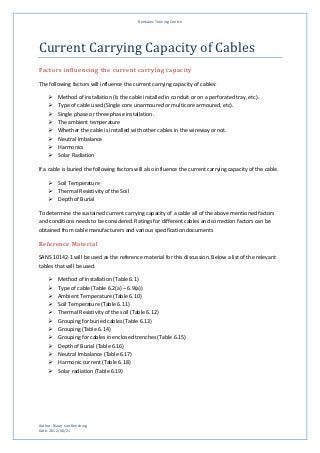
- 1. Renkalec Training Centre Current Carrying Capacity of Cables Factors influencing the current carrying capacity The following factors will influence the current carrying capacity of cables: Method of installation (Is the cable installed in conduit or on a perforated tray, etc). Type of cable used (Single core unarmoured or multicore armoured, etc). Single phase or three phase installation. The ambient temperature Whether the cable is installed with other cables in the wireway or not. Neutral Imbalance Harmonics Solar Radiation If a cable is buried the following factors will also influence the current carrying capacity of the cable. Soil Temperature Thermal Resistivity of the Soil Depth of Burial To determine the sustained current carrying capacity of a cable all of the above mentioned factors and conditions needs to be considered. Ratings for different cables and correction factors can be obtained from cable manufacturers and various specification documents Reference Material SANS 10142-1 will be used as the reference material for this discussion. Below a list of the relevant tables that will be used. Method of Installation (Table 6.1) Type of cable (Table 6.2(a) – 6.9(a)) Ambient Temperature (Table 6.10) Soil Temperature (Table 6.11) Thermal Resistivity of the soil (Table 6.12) Grouping for buried cables (Table 6.13) Grouping (Table 6.14) Grouping for cables in enclosed trenches (Table 6.15) Depth of Burial (Table 6.16) Neutral Imbalance (Table 6.17) Harmonic current (Table 6.18) Solar radiation (Table 6.19) Author: Riaan van Rensburg Date: 2012/06/21
- 2. Renkalec Training Centre Determining sustained current capacity of a cable (Above ground installation) Consider the following installation: A circuit consisting of 3 single cores, unarmoured PVC insulated cables with a size of 16 mm2 supplies a three phase motor. The cables are run in trunking together with 3 other circuits. The ambient temperature is 27 C. The harmonic current is 20% with reference to the phase current. Determine the maximum current that this cable can carry continuously. 1. Determine the method of installation by referring to Table 6.1. According to Table 6.1 on page 91 this is a Method 2 installation. 2. Select the appropriate table according to the cable type. This is single core, unarmoured, PVC insulated cable, and therefore Table 6.2(a) is the correct table to use. 3. Column 4/5 is the correct columns to use for a method 2 installation. 4. This is a three phase circuit and therefore column 5 is the appropriate column to use. 5. A 16mm2 cable has a maximum current carrying capacity of 68 A. Note that this current rating is when the ambient temperature is 30 C, this is the only circuit in the trunking, there is no neutral imbalance, no harmonic current and the cable is not subjected to direct solar radiation. If the above mentioned conditions are not met then correction factors need to be applied to the current obtained from the table. In the scenario sketched above there are influencing factors that necessitates an adjustment of the current. The current can be adjusted by multiplying it with the relevant correction factors. Below is a list of the applicable correction factors: Ambient temperature of 27 C, correction factor of 1 (Table 6.10, pg 124) Grouping of 4 cables in total, correction factor of 0,65 (Table 6.14, pg 129) Harmonic current of 20%, correction factor of 0,86 (Table 6.18, pg 137) The current obtained from Table 6.2 (a) can now be multiplied with the correction factors. This cable can therefore carry 38 A continuously without exceeding its temperature limit of 70 C. Determining sustained current capacity of a cable (Buried cable) Consider the following installation: A 25 mm2 two core cable buried, directly in the ground, 600mm deep in soil with a thermal resistivity of 1, 4 K.m/W delivers current to a single phase water pump. The soil temperature is 20 C and the cable is buried with 2 other cables. The cables are spaced horizontally, 250mm apart. Author: Riaan van Rensburg Date: 2012/06/21
- 3. Renkalec Training Centre 1. Select Table 6.8(a) (pg 114) for buried cables. 2. Columns 2/3 is the correct columns for cables buried directly in the ground. 3. This is a two core cable and therefore column 2 is the correct column to use. 4. A 25 mm2 cable has a maximum current rating of 142 A. Note that this current rating is when the soil temperature is 25 C, it is the only cable in the trench, soil resistivity is 1,2 K.m/W and depth of burial is 500mm. If the above mentioned conditions are not met then correction factors need to be applied to the current obtained from the table. In the scenario sketched above there are influencing factors that necessitates an adjustment of the current. The current can be adjusted by multiplying it with the relevant correction factors. Below is a list of the applicable correction factors: Soil temperature, correction factor of 1,05 (Table 6.11, pg 125) Thermal resistivity of the soil, correction factor of 0,93 (Table 6.12, pg 125) Grouping, correction factor of 0,78 (Table 6.13, pg 126) Depth of burial, correction factor of 0,98 (Table 6.16, pg 134) The current obtained from Table 6.8 (a) can now be multiplied with the correction factors. This cable can therefore carry 105,99 A continuously without exceeding its temperature limit of 70C. Determining cable size required for a known load It is more often the case that a cable selection needs to be made for a known load. The following method can then be used to determine the minimum cable size required. Consider the following installation. A 250kW, 660V motor with a power factor of 0, 85 and efficiency of 87% needs to be connected to the supply using a three core unarmoured cable. The cable will be installed on a perforated cable tray with two other cables. The spacing between the cables will be in excess of two cable diameters. The ambient temperature is 35C. 1. Calculate the current that the motor requires at full load. 2. Select method of installation from table 6.1, pg 93(Method 4). 3. Divide the full load current of the motor by the correction factors 4. Read of the cable size required from Table 6.3, pg 103 Author: Riaan van Rensburg Date: 2012/06/21
- 4. Renkalec Training Centre The correction factors can now be applied by dividing the load current by the correction factors. The following corrections factors apply: Ambient temperature, correction factor of 0,94 (Table 6.10, pg 124) Grouping, no correction factor, spacing exceeding 2De (Table 6.14, pg 129, see note b) The appropriate cable size can now be read off from Table 6.3, pg 104, column 9. According to Table 6.3 a 150mm2 cable can deliver 319 A. Note that the cable will not be required to carry 314, 61 A, but only 295,731 A. The cable will be able to carry 319 A prior to applying any correction factors. To test this, the sustained current carrying capacity can be determined as before. Under the conditions given this cable will be able to carry a maximum current of 299 A. Other factors influencing selection of cable When a cable is selected for a specific installation it is not only the current carrying capacity of the cable that should be considered. Other factors that must also be considered include: Maximum permissible voltdrop. Short circuit withstand rating of the cable. Maximum impedance with regards to the functioning of the short circuit protection. Electromechanical stresses and thermal effects as a result of a short circuit. Mechanical stresses Author: Riaan van Rensburg Date: 2012/06/21