02 wireline
•
39 gostaram•37,931 visualizações

The document provides information on various wellbore equipment manufactured by Parveen including: - Measuring line stuffing boxes that seal around wirelines and incorporate a blow out plug for safety. - Line wipers used to wipe wirelines when removed from wells. - Grease injection control heads that inject grease to create a seal around braided lines. - Lubricator risers that allow wirelines to be raised above wellhead valves. - Blowout preventers available in manual or hydraulic models in various configurations to provide protection during wireline operations.

Recomendados
Mais conteúdo relacionado
Mais procurados
Mais procurados (20)
Destaque
Destaque (19)
Semelhante a 02 wireline
Semelhante a 02 wireline (20)
Último
Último (20)
02 wireline
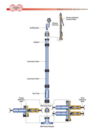
- 1. PARVEEN Wellheads, X-mas Trees, Gate Valves, Manifolds Grease Injection Control Head Sheave Bracket Stuffing Box Adapter Lubricator Riser Lubricator Riser Tool Trap Dual Hydraulic BOP Single Hydraulic BOP Blanking Plug Well Head Adaptor
- 2. PARVEEN Wellheads, X-mas Trees, Gate Valves, Manifolds MEASURING LINE STUFFING BOXES PARVEEN Measuring Line Stuffing Boxes are specifically designed to seal around a stationary or moving solid wireline of all sizes upto 0.125”. PARVEEN Stuffing Boxes incorporate a Blow Out Plug to automatically shut-in the well pressure in the event that the line breaks all the tools are stripped off while working under pressure. Available in working pressure rating from 5,000 PSI to 15,000 PSI, standard or H2S Service, with 8” to 16” diameter sheaves. PARVEEN Measuring Line Stuffing Boxes are designed to be operated either manually or hydraulically without modification. Contact factory for details on pump, fittings, hoses and other accessories. LIGHT WT. STUFFING BOX HYDRAULIC STUFFING BOX STUFFING BOX Engineering Data for Measuring Line Stuffing Boxes SERVICE SHEAVE SIZE (IN) W.P. (PSI) MANUAL PART NO. HYDRAULIC PART NO. H2S 8 5,000 12508 12508-H H2S 10 5,000 12510 12510-H H2S 16 5,000 12570 12570-H STD 10 10,000 12111 12111-H STD 16 10,000 12171 12171-H H2S 10 15,000 12410 12410-H HJ2S 16 15,000 12470 12470-H STD 10 15,000 12411 12411-H STD 16 15,000 12471 12471-H STD 10 5,000 12511 12511-H STD 16 5,000 12571 12571-H H2S 10 10,000 12110 12110-H H2S 16 10,000 12170 12170-H · Bottom Conn : To select From Quick Union Identification Chart Page No. 39 & 40
- 3. PARVEEN Wellheads, X-mas Trees, Gate Valves, Manifolds ‘LW’ LINE WIPER PARVEEN Line Wipers are used to wipe wireline when wireline is removed from well. Line wiper also used to create a seal around braided line. Manual Casing Wipers ID WIPER TYPE WORKING PRESSURE (PSI) LINE SIZE STANDARD BOTTOM CONNECTION 6-1/4 Casing 3,000 7/32-1 7 8 Thread Pin 6-1/2 Casing 3,000 7/32-1 7 8 Thread Box 6-1/2 Casing 3,000 7/32-1 7 Stub Acme Box 2-3/4 Automatic 1,000 3/16-7/8 3-1/2 O.D. LP Pin 3-5/8 Automatic 1,500 3/16-7/8 4-1/2 O.D. LP Pin Casing Line Wiper Manual Line Wipers ID WIPER TYPE WORKING PRESSURE (PSI) LINE SIZE STANDARD BOTTOM CONNECTION 1-9/16 Tubing 5,000 1/8-5/16 2-3/8 EUE Pin 1-3/16 Tubing 5,000 1/8-¾ 2-3/8 EUE Pin 2-5/16 Tubing 5,000 3/16-1 3-1/2 EUE Pin 1-13/16 Solid 2,500 3/16-¾ 2-7/8 EUE Pin 2-5/16 Solid 5,000 3/16-1 2-7/8 EUE Pin 5 Casing 3,000 7/32-1 5-1/2 8 Thread pin 5 Casing 3,000 7/32-1 5-1/2 Stub Acme Box MANUAL LINE WIPER Hydraulic Line Wipers ID WORKING PRESSURE (PSI) LINE SIZE STANDARD BOTTOM CONNECTION 1-3/4 5,000 1/8-½ 2 LP Box 1-3/4 5,000 1/8-½ Union Series 1-1/8 5,000 1/8-½ 2-3/8 EUE Pin 1-13/16 5,000 1/8-¾ 2-7/8 EUE Pin 2-5/16 5,000 1/8-1 2-7/8 EUE Pin 5 5,000 1/8-1 5-1/2 Box 5 5,000 1/8-1 5-1/2 Stub Acme 6-1/4 3,000 7/32-1 7-8 Thread Pin 6-9/16 3,000 7/32-1 7-8 Thread Pin 6-9/16 3,000 7/32-1 7-8 Thread Pin 6-17/32 5,000 7/32-1 7-8 Thread Pin HYDRAULIC LINE WIPER
- 4. PARVEEN Wellheads, X-mas Trees, Gate Valves, Manifolds GREASE INJECTION CONTROL HEADS Grease Injection Control Head (GICH) is required to obtain a seal when using braided line for heavy duty such as swabbing or fishing. Principle of Operation: Grease is injected at a pressure higher than the well pressure (approximately 20% higher). The grease fills the interstitial grooves between the braided line stands. The most critical component of the grease injection head are the `flow tubes'. These should be approximately 0.010” ID larger than the measure ODS of the o-line. The seal is achieved by the pressure drop created across the small gap between the line and flow tubes. A wiper box on top of the grease injection head retains a large percentage of the grease. Ancillary Equipment The following equipment are required to operate the grease injection system ! ! ! ! ! Compressor (Back-up system essential in high pressure situations) Grease reservoir Grease Pump Connection hoses Dual BOP system Use : The following factors will effect the volume of grease required : ! ! ! ! ! ! Clearance between the flow tubes and line Temperature Well pressure Line Speed Line Size Grease viscosity. Engineering Data For Grease / Oil Injection Control Head W.P. (PSI) LOWER CONN. PART NO. 2,000 (Non-STD) 2 EUE PIN 108591 2,000 2 EUE PIN 108591 5,000 2-7/8 EUE PIN 108663 10,000 TO SELECT FROM QUICK UNION IDENTIFICATION CHART PART NO. 39 & 40 108806 GREASE INJECTOR HEAD
- 5. PARVEEN Wellheads, X-mas Trees, Gate Valves, Manifolds LUBRICATOR RISERS PARVEEN Lubricator Risers are used to allow the wireline tool string to be raised above the Wellhead Valve prior to and after wireline operations and therefore enable the Wellhead Valve to be opened and closed allowing entry and exit from the well bore. PARVEEN Lubricator Risers are available in standard lengths from 4 feet through 12 feet, and 2-1/2” through 6.38” bores. Standard end connections include a union box up and union pin and collar (nut) down. Bleed off valves are available in all models upon request. Working pressure ranges for these Risers from 5,000 PSI through 15,000 PSI. Engineering Data for Lubricator Riser PART NO. SERVICE I.D. (INCH) W.P. (PSI) 4 FEET 6 FEET 8 FEET 10 FEET 042557X1 042559X1 STD 2.50 5,000 042553X1 042555X1 STS 3.00 5,000 043553X1 043555X1 043557X11 0435591X1 STD 2.50 10,000 042152X1 042155X1 STD 3.00 10,000 043153X1 043155X1 043157X1 043159X1 H2S 2.50 5,000 042553X0 042555X0 042557X0 042559X0 H2S 3.00 5,000 0423553X0 043555X0 043557X0 043559X0 H2S 2.50 10,000 042153X0 042155X0 042157X0 042159X0 H2S 3.00 10,000 043153X0 043155X0 043157X0 043159X0 STD 2.50 15,000 042453X1 042455X1 042457X1 042459X1 H2S 2.50 15,000 042453X0 042455X0 042457X0 042459X0 H2S 3.00 15,000 043453X0 043455X0 043457X0 043459X0 STD 4.00 5,000 044553X1 044555X1 044557X1 044559X1 H2S 4.00 5,000 044553X0 044555X0 044557X0 044559X0 STD 4.00 10,000 044153X1 044153X1 044157X1 044159X1 042157X1 042159X1 H2S 4.00 10,000 044153X0 044155X0 044157X0 044159X0 H2S 4.00 15,000 044453X0 044455X0 044457X0 044459X0 STD 5.00 5,000 045553X1 045555X1 045557X1 045559X1 STD 5.00 10,000 045153X1 045155X1 045157X1 045159X1 H2S 5.00 5,000 045553X0 045555X0 045557X0 045559X0 H2S 5.00 10,000 045153X0 045155X0 045157X0 045159X0 STD 6.38 5,000 049553X1 049555X1 049557X1 049559X1 H2S 6.38 5,000 049553X0 049555X0 049557X0 049559X0 H2S 6.38 10,000 049153X0 049155X0 049157X0 049159X0 ! Top & Bottom Conn: To select From Quick Union Identification Chart Page No. 39 & 40 LUBRICATOR RISER
- 6. PARVEEN Wellheads, X-mas Trees, Gate Valves, Manifolds BLOWOUT PREVENTERS PARVEEN Blowout Preventers are designed to give positive protection against blow outs when operating with wireline in well services work, by providing a positive seal around wireline. SINGLE WIRELINE BOP MANUAL This BOP’s are available basically in two types: Hydraulically Operated and Manually Operated, with configurations as desired. An equalizer valve allows the operator to equalize the pressure with lubricator pressure. PARVEEN Blow Out Preventers are available in sizes ranging from 2-1/2” ID through 6-3/8” ID and 3000 PSI through 15,000 PSI working pressure. Contact factory for details on pump, fittings, hoses and other accessories. HYDRAULIC SINGLE WIRELINE BOP Engineering Data for Manual and Hydraulic Wireline Blowout Preventer TYPE SINGLE SINGLE SINGLE TWIN TWIN TRIPPLE TRIPLE TRIPPLE QUAD QUAD SINGLE SINGLE TWIN TWIN TRIPPLE TRIPPLE QUAD QUAD SINGLE SINGLE I.D. (INCH) 2.50 2.50 2.50 2.50 2.50 2.50 2.50 2.50 2.50 2.50 3.00 3.00 3.00 3.00 3.00 3.00 3.00 3.00 4.00 4.00 W.P. (PSI) 5,000 10,000 15,000 5,000 10,000 5,000 10,000 15,000 5,000 10,000 5,000 10,000 5,000 10,000 5,000 10,000 5,000 10,000 5,000 10,000 PART NO. (MANUAL) 012563X-00 012100-X00 ------022563X-00 022100X-00 032563X-00 032100X-00 032410X-00 042563X-00 042100X-00 013500X-00 013137X-00 023500X-00 023137X-00 033500X-00 033137X-00 043500X-00 043137X-00 014564X-00 014103X-00 PART NO. (HYDRAULIC) 012563X-H00 012100X-H00 012410X-H00 022563X-H00 022100X-H00 032563X-H00 032100X-H00 032410X-H00 042563X-H00 042100X-H00 013500X-H00 013137X-H00 023500X-H00 023137X-H00 033500X-H00 033137X-H00 043500X-H00 043137X-H00 014564X-H00 014103X-H00
- 7. PARVEEN Wellheads, X-mas Trees, Gate Valves, Manifolds BLOWOUT PREVENTERS HYDRAULIC DUAL WIRELINE BOP HYDRAULIC TRIPLE WIRELINE BOP Engineering Data for Manual and Hydraulic Wireline Blowout Preventer TYPE TWIN TWIN TRIPLE TRIPLE QUAD QUAD SINGLE SINGLE TWIN TWIN TRIPLE TRIPLE QUAD QUAD SINGLE TWIN TRIPLE QUAD I.D. (INCH) 4.00 4.00 4.00 4.00 4.00 4.00 5.00 5.00 5.00 5.00 5.00 5.00 5.00 5.00 6.38 6.38 6.38 6.38 W.P. (PSI) 5,000 10,000 5,000 10,000 5,000 10,000 5,000 10,000 5,000 10,000 5,000 10,000 5,000 10,000 5,000 5,000 5,000 5,000 PART NO. (MANUAL) 024564X-00 024103X-00 034564X-00 034103X-00 044564X-00 044103X-00 015565X-00 015111X-00 025565X-00 025111X-00 035565X-00 035111X-00 045565X-00 045111X-00 700-200-638-2000 700-300-638-2000 700-200-638-3000 700-200-638-4000 Top & Bottom Conn : To Select From Quick Identification Chart Page No. 39 & 40 PART NO. (HYDRAULIC) 024564X-H00 024103X-H00 034564X-H00 034103X-H00 044564X-H00 044103X-H00 015565X-H00 015111X-H00 025565X-H00 025111X-H00 035565X-H00 035111X-H00 045565X-H00 045111X-H00 700-200-638-1000 700-300-638-1000 700-200-638-3001 700-200-638-4001
- 8. PARVEEN Wellheads, X-mas Trees, Gate Valves, Manifolds TOOL TRAPS PARVEEN Tool Traps are available in both hydraulically operated and manually operated models. These tool traps are designed to be installed at the bottom of a lubricator or wellhead setup and prevents the loss of a wireline tool in case the Rope Socket accidentally stripped off. Contact factory for details on pump, fittings, hoses and other accessories. HYDRAULIC TOOL TRAP Engineering Data for Hydraulic Tool Trap SERVICE STD STD H2S H2S STD STD H2S H2S H2S STD H2S H2S STD H2S STD STD STD H2S H2S H2S I. D. (INCH) 2.50 3.00 2.50 3.00 2.50 3.00 2.50 2.50 3.00 4.00 4.00 3.00 4.00 4.00 5.00 5.00 6.38 5.00 5.00 4.00 W.P. (PSI) 5,000 5,000 5,000 5,000 10,000 10,000 15,000 10,000 10,000 5,000 5,000 15,000 10,000 10,000 5,000 10,000 5,000 5,000 10,000 15,000 PART NO. 06251-H 06351-H 06250-H 06350-H 601251 60448 06240-H 69969 06310-H 06451-H 06450-H 06340-H 06411-H 06410-H 06551-H 06511-H 06951-H 06550-H 06510-H 06440-H Manual Tool Trap Hydraulic Tool Trap Top & Bottom : To Select From Quick Union Identification Chart Page No. 39 & 40 MANUAL TOOL TRAP Engineering Data for Manual Tool Trap SERVICE STD STD STD STD STD I.D. (INCH) 2.50 3.00 4.00 5.00 6.38 W.P. (PSI) 5,000 5,000 5,000 5,000 5,000 TOP & BOTTOM CONN. To select from Q.U. Identification chart page no. 39 & 40 PART NO. 6220 62460 6600 61650 06951
- 9. PARVEEN Wellheads, X-mas Trees, Gate Valves, Manifolds GREASE / OIL INJECTION SUPPLY SYSTEM PARVEEN Grease / Oil Injection Supply Systems are used to deliver grease or oil to PARVEEN Grease / Oil Injection Control Head Assemblies , under operating pressures from 2000 PSI to 15,000 PSI with Grease Injection and Grease Return Hoses. Basic design consists of Grease / Oil / Oil Reservoir, Grease / Oil Pump, Pressure and volume control, pressure gauges and necessary piping , valves, fittings and other components to power and control the unit. Engineering Data For Supply System W.P. (PSI) USE WITH CONTROL PART NO. PART NO. 2,000 108591 105412 5,000 108591 108909 5,000 108663 109100 10,000 108661 107005 15,000 108806 103442
- 10. PARVEEN Wellheads, X-mas Trees, Gate Valves, Manifolds WELLHEAD FLANGE ADAPTERS PARVEEN Wellhead Flange Adapters are designed to be used in the upper most position on API Wellheads and therefore enable wireline and other well service operations to be performed through the wellhead into well bore. PARVEEN Wellhead Adapters are available in various bore sizes and with quick union connections compatible with Bowen and Otis type quick unions. Additionally, flange/Adapters are supplied for standard or H2S Service and working pressure upto 15,000 PSI. Engineering Data for Wellhead Flange Adapters SERVICE H2S STD H2S STD H2S STD H2S STD STD STD H2S H2S H2S H2S H2S H2S H2S H2S H2S H2S H2S STD STD STD STD STD STD STD ! ! ! FLANGE ADAPTER I.D. (INCH) 2.06 2.06 2.50 2.50 3.00 3.00 2.56 2.56 2.06 2.50 2.06 2.50 2.56 3.00 3.06 3.12 2.06 2.50 3.00 3.06 4.00 2.06 2.50 3.00 3.12 3.06 4.00 4.00 W.P. (PSI) 5,000 10,000 5,000 10,000 5,000 10,000 5,000 10,000 15,000 15,000 10,000 10,000 10,000 5,000 5,000 15,000 15,000 15,000 10,000 10,000 5,000 5,000 5,000 5,000 10,000 5,000 5,000 10,000 PART NO. 5115XX0 5111XX1 5125XX0 5121XX1 5135XX0 5131XX1 51115XX0 51111XX1 5114XX1 5124XX1 5111XX0 5121XX0 51111XX0 5131XX0 51125XX0 51135XX0 5114XX0 5124XX0 5134XX0 51121XX0 5141XX0 5115XX1 5125XX1 5135XX1 51135XX1 51121XX1 5145xx1 5141xx1 Quick Union Size: To Select From Quick Union Identification Chart Page No. 39 & 40 Flange Size & Type: Customer to Specify as per API 6A Other Size Available on Request
- 11. PARVEEN Wellheads, X-mas Trees, Gate Valves, Manifolds API ADAPTERS PARVEEN API Threaded Adapters have an API pin thread down and a quick box connection up. These adapters are used for lower working pressure. Any combination of end connections are available on request. Engineering Data for Crossover Adapter SERVICE I.D. (INCH) W.P. (PSI) BOTTOM CONN. PART NO. STD 2.067 5,000 2-11.5 V Line Pipe 134-025011 H2S 2.067 5,000 2-11.5 V Line Pipe 134-025010 STD 1.995 5,000 2-3/8 EU 8 rd 134-015021 H2S 1.995 5,000 2-3/8 EU 8 rd 134-015020 STD 2.441 5,000 2-7/8 EU 8 rd 134-035031 H2S 2.441 5,000 2-7/8 EU 8 rd 134-035030 STD 2.500 5,000 3-1/2 EU 8 rd 134-045041 H2S 2.500 5,000 3-1/2 EU 8 rd 134-045040 STD 2.992 5,000 3-1/2 EU 8 rd 134-055041 H2S 2.992 5,000 3-1/2 EU 8 rd 134-055040 STD 3.476 5,000 4 EU 8 rd 134-065051 H2S 3.476 5,000 4 EU 8 rd 134-065050 H2S 3.958 5,000 4-1/2 EU 8 rd 134-075060 STD 3.598 5,000 4-1/2 EU 8 rd 134-075061 H2S 4.000 5,000 4-1/2-8 rd long casing 134-085070 STD 4.000 5,000 4-1/2-8 rd long casing 134-085071 H2S 4.000 5,000 5-1/2-8 rd long casing 134-085080 STD 4.890 5,000 5-1/2-8 rd long casing 134-105081 STD 3,000 7-8 rd long casing 134-113091 5.000 5,000 7-5/8-8 rd long casing 134-115101 H2S 4.670 5,000 5-1/2-8 rd long casing 134-095080 H2S 5.000 3,000 7-8 rd long casing 134-113090 H2S 5.000 5,000 7-5/8-8 rd long casing 134-115100 STD 5.000 5,000 9-5/8-8 rd long casing 134-115111 H2S 5.000 5,000 9-5/8-8 rd long casing 134-115110 STD 6.375 5,000 9-5/8-8 rd long casing 134-135111 H2S 6.375 5,000 9-5/8-8 rd long casing 134-135110 STD 6.090 3,000 7-8 rd long casing 134-123091 H2S ! 5.000 STD 6.090 3,000 7-8 rd long casing 134-123090 Top Conn : To Select From Quick Union identification Chart Page No. 39 & 40. TUBING PIN X THREADED HALF
- 12. PARVEEN Wellheads, X-mas Trees, Gate Valves, Manifolds QUICK UNION PARVEEN Quick Union Connections are used to assemble lubricators and related equipment and they are designed to be assembled by hand. Otis type and Bowen Type designs are commonly used. A O-Ring on the pin section forms the seal when made up into the box. The collar has an internal ACME threads to match the external threads on the box. This threads mix-up quickly by hand. E (SEAL) C B A G G D B UNION PIN AND NUT UNION BOX (TPI = F) 1 A PARVEEN QUICK UNION IDENTIFICATION CHART PARVEEN (A) W.P.(PSI) SERV B C D E F G PART NO. 5.000-4 ACME TYPE O STD 2.50 3.00 3.494 3.5 50236 4 5.000 440100 5.000-4-ACNE TYPE O 10,000 STD 2.50 3.00 3.494 3.5 50338 4 5.000 440100 5.000-4 ACME TYPE O 15,000 STD 2.50 3.494 3.5 50338* 4 5.000 440101 5.750-4 ACME TYPE O 5,000 10,000 H2S 2.50 3.00 3.994 4.00 50342* 4 5.750 440200 6.250-4 ACME TYPE O 15,000 H2S 2.50 3.994 4.00 50342* 4 6.250 440301 6.500-4 ACME TYPE O 5,000 10,000 STD 4.00 4.744 4.750 50348 4 6.500 440400 7.500-4 ACME TYPE O 15,000 H2S 3.00 5.494 5.500 50354* 4 7.500 440701 8.250-4 ACME TYPE O 5,000 10,000 STD 5.00 6.182 6.188 50435 4 8.250 440800 8.375-A ACME TYPE O 5,000 10,000 H2S 4.00 5.244 5.250 50427 4 8.375 440900 8.750-4 ACME TYPE O 5,000 STD 6.38 7.494 7.500 50441 4 8.750 441100 9.000-4 ACME TYPE O 5,000 10,000 H2S 5.00 6.744 6.750 50438 4 9.000 441200 9.500-4 ACME TYPE O 15,000 H2S 4.00 6.244 6.250 50435* 4 9.500 441601 9.500-4 ACME TYPE O 5,000 H2S 6.38 7.994 8.000 50443 4 9.500 441400 11.500-4 ACME 10,000 TYPE O * SEAL GROOVE WILL HAVE THIS CONFIGURATION 5000 H2S 6.38 8.244 8.250 50444 4 11.500 441800 PARVEEN Type O Union Are Interchangeable With Otis Union
- 13. PARVEEN Wellheads, X-mas Trees, Gate Valves, Manifolds QUICK UNION A E (SEAL) C B G D G B UNION PIN AND NUT UNION BOX (TPI = F) 1 A PARVEEN QUICK UNION IDENTIFICATION CHART PARVEEN (A) W.P. (PSI) SERV. B C D E F G PART NO 4.750-4 ACME TYPE B 5,000 STD H2S 2.50 3.744 3.00 3.750 50340 4 4.750 440110 4.750-4 ACME TYPE B 10,000 STD 2.50 3.744 3.00 3.750 50340* 4 4.750 440111 5.500-4 ACME TYPE B (DL) 5,000 STD H2S 3.00 4.369 4.375 50345* 4 5.500 440211 5.500-4 ACME TYPE B (DL) 10,000 STD 3.00 4.369 4.375 50345* 4 5.500 440211 6.312-4 ACME TYPE B 10,000 H2S 2.50 4.369 3.00 4.375 50345** 4 6.312 440311 6.312-4 ACME TYPE B 15,000 STD 2.50 4.369 4.375 50345* 4 6.312 440312 6.312-4 ACME TYPE B 15,000 H2S 2.50 3.744 3.750 50340** 4 6.312 44012 7.000-5 SA TYPE B 5,000 STD H2S 4.00 5.244 5.250 5 7.000 440510 7.093-4 ACME TYPE B 15,000 STD H2S 3.00 4.744 4.750 50348** 4 7.093 440612 8.250-4 ACME TYPE B (DL) 10,000 STD H2S 4.00 5.994 6.000 50358* 4 8.250 440811 8.250-4 ACME TYPE B (DL) 5,000 STD H2S 5.00 6.744 6.750 50438 4 8.250 440710 50427 PARVEEN Type B Union Are Interchangeable With Bowen Unions. * SEAL GROOVE WILL HAVE THIS CONFIGURATION ** SEAL GROOVE WILL HAVE THIS CONFIGURATION
- 14. PARVEEN Wellheads, X-mas Trees, Gate Valves, Manifolds BLANKING CAP & PLUG PARVEEN Blanking Cap and Blanking Plugs are used for installing gauge and / or Bleed Off Valve. They are available for use on all Quick Unions, and are equipped with NPT ports. BLANKING PLUG BLANKING CAP PUMP IN SUB The Pump-In Sub is placed between wireline BOP and the Wellhead. It is basically used to pump the fluid in well when wireline BOP is closed. Pump-In Sub can also be used for injection of inhibitors and for collecting samples. It has top and bottom with Quick Union Connections and side outlet with Wing Union Connection. Engineering Data for Pump-In Sub ID W.P (PSI) SERVICE 2-1/2 5,000 STD 2-1/2 5,000 H2S 2-1/2 10,000 STD. 2-1/2 10,000 H2S 3 10,000 STD 3 10,000 H2S 4 10,000 H2S 5.12 10,000 H2S 6-3/8 10,000 H2S PUMP IN SUB W/WECO UNION ON SIDE
- 15. PARVEEN Wellheads, X-mas Trees, Gate Valves, Manifolds LUBRICATOR ACCESSORIES Union Cross Over Adapters can be utilized to provide transition between otherwise incompatible unions made by same or different manufacturers. These adapters are designed with a Union Box Up and Union Pin & Collar Down and are always rated, both in terms of service and pressure. Any combination of end connections are available upon request. Floor Block (Hay Pulley) is used to bring the wireline down to a position where it is horizontal from the tree to the wireline rig. It also shifts the point of wireline pull from the top of lubricator to the base of tree and reduces side loading of the lubricator. Engineering Data for Hay Pulley Pulley Dia (IN) Groove Dia Type Connection Safe Working Load (lbs) Part No. 7 Customer Swivel Hanger 3,000 330700 10 to Swivel Hanger 5,000 331000 12 specify Swivel Hanger 5,000 331200 Swivel Hanger 5,000 331400 14 Wireline Clamp is used to clamp the wireline while Assembly No. Description raising or lowering the 15XXX00 For all sizes of smooth wireline for lubricator or during fishing 15XXX10 3/16-in and ¼- braided wireline operations. Wellhead Connection is used to connect the bottom of the wireline valve to the top tree connections. The top of the connection fits the bottom of valve and the bottom thread of connection is threaded to screw into the particular threads on top of the tree flange connections. Telescopic Gin Pole is used to rise the lubricator to the top of the wireline valve and maintain this position while breaking off or making up wireline tool string. Assembly No. Description 38XXX10 38XXX00 38XXX20 Steel for standard weight lubricators Aluminium for standard weight lubricators Steel for standard weight, high-pressure lubricators Load Binder and Chain are used to bind the gin pole to the tree and to the wireline valve. Rope Blocks are used to raise and lower the lubricator. Lubricator Pick-Up Clamp is used to hook rope block to pick up lubricator. Pump - In - Subs and Plug Valves are used to pressurize the lubricator during hydrostatic testing or pumping in to the well bore when that become necessary during the course of servicing operations. Models with WP. above 5,000 PSI are equipped with specially designed side ports and accept plug valves with integral unions. Plug Valves are available separately and as a component of Pump-in-Subs. Fitted with a variety of Top and Bottom Connection, - Quick Union connections being most common, - these assemblies are available from 2.50 ID. inch through 6.38" ID. with WP from 3,000 PSI through 15,000 PSI.
- 16. PARVEEN Wireline Pressure Control Equipment & Tool String WIRELINE TOOL STRING The Wireline Tool String is necessary for the efficient surface control during the running and pulling operations on slickline of sub surface controlled devices. Rope Socket An assembly of wireline tools connected to the wireline is used to deliver surface control impacts (jar action) either upwards or downwards to manipulate devices within the well bore. A standard set of wireline tool string typically consist of : Stem Wireline Socket (Rope Socket) for attaching the wireline to the tool string. Wireline Stem (Sinker Bar) for adding weight to sink the tool in the well bore against the well pressure and different gravity fluids encountered. Wireline Jars (Spang Link Jar) for securing the hammering effect by upward or downward movement. Wireline Knuckle Joint for obtaining flexibility through the tool string. Wireline running or pulling tool for running and retrieving devices from the well bore. Stem All Wireline Tools are available with following: Sucker Rod Threads UN Threads Quick Lock Connection ! ! ! Customer to choose the type of connection they want to use in wireline tool string. Sucker rod threads are machined on wireline tools asper API 11B. These are economical cost wise. Mechanical Jars UN threads are also machined on wireline tools and are interchangeable with Sucker Rod Threads but are shorter in length. These are also economical cost wise. Quick Lock Connector as the name suggest is a quick connect and quick disconnect connection, which is used in place of screwed connection. It has many advantages over screwed connection: ! ! Knuckle Joint (Optional) It is quarter turn connection. It is stronger than screwed connection. It has three impact load bearing surfaces in each direction, which make it safer for heavy and prolonged wireline operations. ! It is safer and simpler and can be released with a screwdriver.
- 17. PARVEEN Wireline Pressure Control Equipment & Tool String ROPE SOCKET PARVEEN Rope Sockets are used as a means to connect wireline to the tool string. Rope Sockets are available in 4 types as under: SPOOL TYPE WEDGE TYPE SLIP TYPE CLAMP TYPE Engineering Data for Rope Socket SIZE F/N. O.D. THREAD CONN. WIRE SIZE (IN.) (IN.) (IN) BOX (IN. TPI) (IN) 1 1.000 0.875 5/8-11 UNC 1-1/4 1.250 1.187 1-1/2 1.500 2-1/2 TYPE PART NO. 0.066-0.092 SPOOL 911000-SP 15/16-10 UN 0.066-0.092 SPOOL 911211-SP 1.375 15/16-10 UN 0.066-0.092 SPOOL 911521-SP 2.500 2.312 1-9/16-1O UN 0.092 SPOOL 912546-SP 1-7/8 1.750 1.875 1-1/16-10 UN 0.066-0.092 SPOOL 911932-SP 2-1/8 2.125 1.750 1-1/16-10 UN 0.092 SPOOL 912132 SP 1-1/8 1.125 0.875 5/8-11 UNC 0.066-0.092 WEDGE 911100-W 1-1/2 1.500 1.375 15/16-10 UN 0.092/0.108 WEDGE 911521-W 1-1/2 1.50 1.375 1-1/16-10 UN 0.092/0.108 WEDGE 911522-W 1-7/8 1.875 1.750 15/16-10 UN 0.092/0.108 WEDGE 911931-W 1-7/8 1.875 1.750 1-1/16-10 UN 0.092/0.108 WEDGE 911932-W 2-1/8 2.125 1.750 1-1/16-10 UN 0.092/0.108 WEDGE 912132-W 2-1/2 2.500 2.312 1-9/16-10 UN 0.092/0.108 WEDGE 912546-W 1-1/4 1.250 1.187 15/16-10 UN 0.125 CLAMP 911211-C 1-1/2 1.500 1.375 15/16-10 UN 0.125/0.187 CLAMP 911521-C 1-7/8 1.875 1.750 1-1/16-10 UN 0.187 CLAMP 911932-C 2-1/2 2.500 2.312 1-9/16-10 UN 0.250 CLAMP 912546-C 1-1/2 1.500 1.375 15/16-10 UN 0.187 SLIP 911521-SL 1-7/8 1.875 1.750 1-1/16-10 UN 0.187 SLIP 911936-SL 2-1/8 2.125 1.750 1-1/16-10 UN 0.187 SLIP 912132-SL 2-1/2 ! MAX. O.D. 2.500 2.312 1-9/16-10 UN 0.187 SLIP 912546-SL Other sizes available on request
- 18. PARVEEN Wireline Pressure Control Equipment & Tool String ‘S’ WIRELINE STEM (WEIGHT BAR) PARVEEN Wireline Stems are used to provide weight to tool string to eliminate friction with elastomers of stuffing box and for smooth running of wireline against well pressure. Wireline stems are available in various Lengths, ODs, Connections. Engineering Data for Wireline Stem SIZE (IN.) MAX. O.D. (IN.) F/N. O.D. THREAD CONN. (IN) PIN X BOX (IN. TPI) 2 FT LONG PART NO 3 FT. LONG 5 FT LONG 1 1.000 0.875 5/8-11 UNC 16105100 16105200 16105400 1-1/4 1.250 1.187 15/16-10 UN 16125111 1612511 16125411 1-1/2 1.500 1.375 15/16-10 UN 16155121 16155221 16155421 1-7/8 1.875 1.750 1-1/16-10 UN 16195132 16195232 16195432 2-1/8 2.125 1.750 1-1/16-10 UN 16215132 16215232 16215432 2-1/2 2.500 2.312 1-9/16-10 UN 16255145 16255245 16255445 ! Other sizes available on request WIRELINE STEM (WEIGHT BAR) ‘LS’ LEAD FILLED STEM PARVEEN Lead Filled Stems are used to provide additional weight to tool string, without change in OD & Length. These are normally used in well bores with high pressure, to eliminate friction with elastomers of stuffing box and for smooth running of wireline against well pressure. Engineering Data for Wireline Lead Filled Stem SIZE (IN.) MAX. O.D. F/N. O.D. (IN.) (IN) THREAD CONN. PIN X BOX (IN. TPI) 2 FT LONG PART NO 3 FT. LONG 5 FT LONG 1-1/4 15/16-10 UN 55125111 55125211 55125411 1.500 1.375 15/16-10 UN 55155121 55155221 55155421 1-7/8 1.875 1.750 15/16-10 UN 55195132 55195132 55195432 2-1/8 LEADED STEMS 1.187 1-1/2 ! 1.250 2.125 1.750 15/16-10 UN 55215132 55215232 55215432 Other sizes available on request.
- 19. PARVEEN Wireline Pressure Control Equipment & Tool String ‘SM’ ROLLER STEM PARVEEN Roller Stems are used with tool string in deviated wells. Its application is to reduce friction against tubing ID. In assembly of Roller Stems : Teflon / Alloy Steel Rollers (suitable for high temperature / H2S Service), specialty bearings are assembled with body. Roller Stems are available in various Lengths, ODs, Connections and Rollers dia. Engineering Data for Roller Stem SIZE (IN.) ! MAX. O. D. (IN.) F/N O.D. (IN.) 1-1/2 2.00 1.375 1-7/8 2.50 1.750 2-1/2 3.00 2.312 1-1/2 2.00 1.375 1-7/8 2.50 1.750 2-1/2 3.00 2.312 Other sizes available on request. THREAD CONN. PIN X BOX (IN. - TPI.) 15/16-10 UN 1-1/16-10 UN 1-9/16-10 UN 15/16-10 UN 1-1/16-10 UN 1-9/16-10 UN NO. OF WHEELS PART NO. 3 3 3 4 4 4 52200321 52250332 52300346 52200421 52250432 52300446 ROLLER STEM ‘MJ’ SPANG LINK JARS OR MECHANICAL JARS PARVEEN Spang Link or Mechanical Jars are used in wireline fishing operations with stems. The weight of stems and jars can be used by operator for jarring by pulling and then releasing wireline. These Jars are available in various sizes and strokes. Force =Mass x Acceleration. Stem weight is fixed but speed can be varied. In jar down action, speed is limited due to limited travel and gravity. Jar of action is more effective as speed can be increased by increasing the spooling speed of wireline unit and using long jars. Engineering Data for Spang Link Jars or Mechanical Jar SIZE (IN.) ! MAX. O.D. (IN.) F/N. OD (IN.) 1 1.000 0.875 1 1.000 0.875 1-1/4 1.250 1.187 1-1/4 1.250 1.187 1-1/4 1.250 1.187 1-1/2 1.500 1.375 1-1/2 1.500 1.375 1-7/8 1.875 1.750 1-7/8 1.875 1.750 1-7/8 1.875 1.750 2-1/8 2.125 1,750 2-1/2 2.500 2.312 Other sizes available on request. THREAD CONN. PIN X BOX (IN. TPI) 5/8-11 UNC 5/8-11 UNC 15/16-10 UN 15/16-10 UN 15/16-10 UN 15/16-10 UN 15/16-10 UN 1-1/16-10 UN 1-1/16-10 UN 1-1/16-10 UN 1-1/16-10 UN 1-9/16-10 UN STROKE (IN.) PART NO. 20 24 20 24 30 20 24 20 24 30 30 24 11102000 11102400 11122011 11122411 11123011 11152021 11152421 11192032 11182432 11193032 11213032 11252446 SPANG LINK JAR
- 20. PARVEEN Wireline Pressure Control Equipment & Tool String ‘TJ’ WIRELINE TUBULAR JAR PARVEEN Tubular Jars are used in tool string for effective jarring. Tubular Jars are commonly used to remove obstacles from the tubing ID by jarring. This is an effective tool during fishing of wire as possibility of Tubular Jar getting jammed with wire is minimal. SIZE (IN.) Engineering Data for Wireline Tubular Jar MAX. O.D. THREAD F/N. PIN X BOX STROKE (IN.) OD (IN.) (IN. TPI) (IN.) PART NO. 1 1.000 0.875 5/8-11 UNC 18 21101800 1 1.000 9.875 5/8-11 UNC 20 21102000 1-1/8 1.125 0.875 5/8-11 UNC 18 21111800 1-1/4 1.250 1.187 15/16-10 UN 20 21122011 1-1/4 1.250 1.187 15/16-10 UN 24 21122411 1-1/4 1.250 1.187 15/16-10 UN 30 21123011 1-1/2 1.500 1.375 15/16-10 UN 20 21152021 1-1/2 1.500 1.375 15/16-10 UN 24 21152421 1-1/2 1.500 1.375 15/16-10 UN 30 21153021 1-3/4 1.750 1.375 15/16-10 UN 20 21172021 1-3/4 1.750 1.375 15/16-10 UN 30 21173021 1-7/8 1.875 1.750 1-1/16-10 UN 20 21192032 1-7/8 1.875 1.750 1-1/16-10 UN 30 21193032 2-1/8 2.125 1.750 1-1/16-10 UN 20 21212032 2-1/8 2.125 1.750 1-1/16-10 UN 24 21212432 2-1/8 2.125 1.750 1-1/16-10 UN 30 21213032 2-1/2 2.500 2.312 1-9/16-10 UN 24 21252446 2-1/2 2.500 2.312 1-9/16-10 UN 30 21253046 ! Other Sizes Available On Request. ‘HJ’ HYDRAULIC JAR PARVEEN Hydraulic Jars are used for jarring when difficulty is face to obtain good jarring action with Mechanical Jars, particularly due to deviated wells or wells with highly viscous fluids. These jars provide only up stroke and are run between stem and Mechanical Jar. Engineering Data for Hydraulic Jar SIZE (IN.) TUBULAR JAR MAX. O.D. (IN.) F/N. OD (IN.) THREAD PIN X BOX (IN. TPI) STROKE (IN.) PART NO. 1-1/8 1.125 0.875 5/8-11 UNC 6.750 081100 1-1/4 1.250 1.187 15/16-10 UN 9.250 081211 1-1/2 1.500 1.375 15/16-10 UN 9.187 081521 1-3/4 1.750 1.375 1-1/16-10 UN 10.00 081722 2-1/8 2.125 1.750 1-3/16-10 UN 11.625 082135 ! Other Sizes Available On Request. HYDRAULIC JAR
- 21. PARVEEN Wireline Pressure Control Equipment & Tool String ‘SPJ’ SPRING JAR PARVEEN Spring Jars are used to provide upward jarring during wireline fishing operations. Spring Jars can be used in place of Hydraulic Jar. These Jars are run between Stem and Mechanical Jar in tool string. Engineering Data for Spring Jar SIZE (IN.) MAX. O.D. (IN.) F/N. O.D. (IN) THREAD CONN. PIN X BOX(IN. TPI) STROKE (IN.) PART NO. 1-1/2 1.500 1.375 15/16-10 UN 12 56151221 1-7/8 1.875 1.750 1-1/16-10 UN 12 56181232 2-1/2 2.500 2.312 1-9/16-10 UN 12 56251246 ! Other Sizes Available On Request ‘WA’ WIRELINE ACCELERATOR PARVEEN Wireline Accelerator is used to run with Hydraulic Jar to reduce shocks at Rope Socket to avoid pulling of wire out of socket and accelerate movement of stem, to achieve effective jarring. Accelerator facilitate constant pull at the time of opening of Hydraulic Jar. Engineering Data for Wireline Accelerator SIZE (IN.) F/N. O.D. (IN) THREAD CONN. PIN X BOX(IN. TPI) LENGTH (IN.) PART NO. 1-1/2 1.500 1.375 15/16-10 UN 22 53152221 1-7/8 SPRING JAR MAX. O.D. (IN.) 1.875 1.750 1-1/16-10 UN 26 53182632 2-1/8 2.125 1.750 1-1/16-10 UN 38 53213832 2-1/2 2.500 2.312 1-9/16-10 UN 35 53253546 3 3.000 2.312 1-9/16-10 UN 38 53303846 ! Other Sizes Available On Request WIRELINE ACCELERATOR
- 22. PARVEEN Wireline Pressure Control Equipment & Tool String ‘SH’ SHOCK ABSORBER PARVEEN Wireline Shock Absorber is used to reduce the shocks to sub surface instruments, caused due to jarring, surging etc. Engineering Data for Wireline Shock Absorber SIZE (IN.) F/N. OD (IN.) TOP CONNECTION PIN (IN. TPI) BOTTOM CONNECTION (BOX) (IN. TPI) PART NO. 1.50 1.375 15/16-10 UN ¾ - 16 UNF 301521 1.75 1.375 15/16-10 UN ¾ - 16 UNF 301721 2.00 1.375 15/16-10 UN ¾ - 16 UNF 302021 ! Other Sizes Available On Request ‘KJ’ KNUCKLE JOINTS PARVEEN Knuckle Joints are used to add flexibility to the tool string and Knuckle Joints are effective in deviated wells. Whenever Stem and jar are not aligned or not moving freely it is impossible to operate tools. However adding knuckle joint in a string this situation can be avoided. Knuckle Joints are run immediately below Mechanical Jar. For additional flexibility additional Knuckle Joint can be included between Stem and Jar. Engineering Data for Knuckle Joints SIZE (IN.) F/N. O.D. (IN) THREAD CONN. PIN X BOX (IN. TPI) PART NO. 1-1/8 1.125 0.875 5/8-11 UNC 071100 1-1/4 1.250 1.187 15/16-10 UN 071211 1-1/2 1.500 1.375 15/16-10 UN 071521 1-7/8 SHOCK ABSORBER MAX. O.D. (IN.) 1.875 1.750 1-1/16-10 UN 071932 2-1/8 2.125 1.750 1-1/16-10 UN 072132 2-1/2 2.500 2.312 1-9/16-10 UN 072546 ! Other Sizes Available On Request KNUCKLE JOINT
- 23. PARVEEN Wireline Pressure Control Equipment & Tool String ‘KJA’ KNUCKLE JAR PARVEEN Knuckle Jars are used as a combination of functions of Knuckle Joint & Short Tubular Jars. Knuckle Jars can be utilized to jar with short strokes to free the string. Like in PARVEEN Knuckle Joint, PARVEEN Knuckle Jar too has specially designed double fishing neck. Engineering Data for Knuckle Jar SIZE (IN.) MAX. O.D. (IN.) F/N. OD (IN.) THREAD PIN X BOX (IN. TPI) STROKE (IN.) PART NO. 1-1/4 1.250 1.187 15/16-10 UN 2 20120211 1-1/2 1.500 1.375 15/16-10 UN 2 20150221 1-1/2 1.500 1.375 15/16-10 UN 4 20150421 1-7/8 1.875 1.750 1-1/16-10 UN 6 20190632 2-1/8 2.125 1.750 1-1/16-10 UN 6 20210632 2-1/2 2.500 2.312 1-9/16-10 UN 6 20250646 ! Other Sizes Available On Request. ‘QC’ QUICK LOCK COUPLINGS PARVEEN Quick Couplings are used as a fast, safe & strong method of tool coupling. Coupling can be made by hand , eliminating requirement of wrenches / spanners etc. KNUCKLE JAR Engineering Data for Quick Lock Coupling SIZE (IN.) MAX. O.D. (IN.) F/N. O.D. (IN) THREAD CONN. PIN X BOX (IN. TPI) PART NO. 1-1/4 1.250 1.187 15/16-10 UN 052511 1-1/2 1.500 1.375 15/16-10 UN 051521 1-7/8 1.875 1.750 1-1/16-10 UN 051932 2-1/2 2.500 2.312 1-9/16-10 UN 052456 ! Other Sizes Available On Request. QUICK LOCK COUPLING
- 24. PARVEEN Wireline Pressure Control Equipment & Tool String ‘TS’ TUBING SWAGE PARVEEN Tubing Swages are used to remove large obstructions and restore light collapse in the tubing. This allows smooth running of tool string in well bore. The OD of tubing swage should be equal to tubing drift ID. It should be run with up stroke jar to enable operator to take it out of tubing if swage is jammed. Engineering Data for Tubing Swage SIZE (IN) MAX O.D. (IN) F/N O.D. (IN) THREAD CONN. PIN (IN.-TPI) PART NO 1.1/2 1.187 15/16-10 UN 101511 1.906 1.375 15/16-10 UN 102021 2.1/2 2.344 1.375 15/16-10 UN 102321 3 2.937 1.750 1.1/16-10 UN 103032 4 ! 1.521 2 3.720 1.750 1.1/16-10 UN 103732 Other Sizes Available On Request. TUBING SWAGE ‘TC’ TUBING GAUGE / PARAFFIN CUTTER PARVEEN Gauge / Paraffin Cutters are run in hole before running sub surface equipment. Gauge / Paraffin Cutters are used to check if sub surface equipment can pass freely thru tubing & there are no obstructions and to locate top of nipple. The bottom of Gauge / Paraffin Cutter is suitable to cut paraffin , scale and any other obstacles in tubing. Selection of size : Example Nipple bore = 2.25" No Go ID = 2.197" So, Gauge Cutter should be between above two sizes. Engineering Data for Tubing Gauge / Paraffin Cutters O.D. RANGE (IN) * 0.905 - 1.575 1.655 - 2.265 2.323 - 2.520 2.598 - 2.953 2.992 - 3.900 5.750 - 6.151 F/N O.D.(IN) 0.875 1.375 1.375 1.750 2.312 2.312 THREAD CONN. PIN (IN.-TPI) 5/8 - 11 UNC 15/16 - 10 UN 15/16 - 10 UN 1.1/16 - 10 UN 1.1/16 - 10 UN 1.9/16 - 10 UN PART NO 831600 832231 832521 832932 833942 836146 TUBING GAUGE / PARAFFIN CUTTER *Tubing Gauge / Paraffin Cutter are available in MM. increments within the Specified O.D. Ranges. When ordering , specify required O.D. in MM ( Inches x 25.4 = MM)
- 25. PARVEEN Wireline Pressure Control Equipment & Tool String ‘BB’ BLIND BOX Parveen Blind Boxes are used when heavy downward jarring is required to dislodge a fish or push something down the hole. Bottom surface of Blind Box is flat and hardened to reduce wear and damage. Engineering Data for Blind Box O.D. RANGE (IN) * F/N O.D. (IN) THREAD CONN. PIN (IN.-TPI) PART NO 1.187 - 1.250 1.187 15/16 - 10 UN 221211 1.625 - 1.375 1.375 15/16 - 10 UN 222221 2.625 - 2.750 1.750 1.1/16 - 10 UN 222732 3.500 - 4.625 2.312 1.9/16 - 10 UN 224646 5.250 - 5.750 2.312 1.9/16 - 10 UN 225746 * Blind Boxes are available in MM. Increments Within The Specified O.D. Ranges. When Ordering, Specify Required O.D. In MM. (Inches x 25.4 = MM) BLIND BOX ‘TL’ TUBING END LOCATOR PARVEEN Tubing End Locators are used to locate end of tubing during completions. With its spring loaded finger, it can be run in various sizes of tubing ranging from 2.3/8" till 4.1/2". Engineering Data for Tubing End Locator SIZE (IN) F/N O.D. (IN) TOP CONN. PIN (IN.-TPI) BOTTOM CONN. PIN (IN. - TPI) PART NO. 2 - 2.1/2 1.750 1.375 15/16 - 10 UN 1 - 11.1/2 NPT 421721 3 2.500 1.375 15/16 - 10 UN 1 - 11.1/2 NPT 422521 4 * MAX O.D. (IN)* 3.750 2.312 1.9/16 - 10 UN 1 - 11.1/2 NPT 423746 O.D. With Finger Sheared ! Other Sizes available on request. TUBING END LOCATOR
- 26. PARVEEN Wireline Pressure Control Equipment & Tool String ‘SB’ SAMPLE BAILER ‘SB’ SAMPLE BAILER The PARVEEN Sample Bailer is used to collect samples of debris from the well bore creating obstructions. PARVEEN Sample Bailer are available in two basic designs with ball or flapper shoe. The shoe opens when sample bailer assembly is forced in debris and closes when the sample bailer is forced out. SIZE (IN.) 1.5 1.75 2 2.5 3 4 Engineering data for `SB' Sample Bailer F/N OD (IN.) CONNECTING THREAD BOX (IN. TPI) 1.375 15/16-10 UN 1.375 15/16-10 UN 1.75 1-1/16-10 UN 2.313 1-1/16-10 UN 2.313 1-1/16-10 UN 2.313 1-9/16-10 UN PART NO. 051 - 001 051 - 002 051 - 003 051 - 004 051 - 005 051 - 006 SAND PUMP BAILER The pump bailer is used to remove the bulk of sand above the wireline tools / equipment. It is a hollow tube with a check valve (ball or flapper) at its lower end, which is usually mule shoe (cut at 45O). It contains a piston and valve attached to a rod which passes through a loose hold ( for fluid bypass) at the upper end of the tube. This rod is attached to the tool string. As the bottom of the bailer rests on the sand, the weight of the tool string pushes the piston to the bottom of the tube. As this piston is picked up, it sucks sand and debris into the bottom of the bailer. This slow ' stroking process' continues until the bailer is full. SAMPLE BAILER HYDROSTATIC BAILER A hydrostatic bailer consists of a chamber sealed at atmospheric pressure. When the bailer reaches the top of the sand and is jarred down, a shear disk is ruptured and the bottom hole pressure surging into the chamber sucks up the sand. A ball check in the bottom serves to trap the sand in the chamber. These bailer are used to clean off sand or foreign materials from around a fishing neck very successfully and are not recommended for normal bailing operations. In soft sand , this bailer will bury itself each time it goes off. It usually requires a hard object against which to shear the disc. Always use a pump bailer to remove the bulk of sand etc. until pump bailer is resting on the plug or whatever is to be removed. A hydrostatic bailer can then be used to clean around the fishing neck. Hydrostatic bailer are not recommended for normal bailing operations because : ! Too slow ! A high possibility of sticking in the sand due to suction action when the sealed chamber is opened. The sand pumps and hydrostatic bailer can be dangerous after pulling them to the surface and when unloading the sand , due to pressure trapped inside the chamber. Caution should be taken when removing the check valve on the bottom to make sure there is no pressure inside. This can be determined usually by how hard the bottom is to unscrew. Once should never completely remove the bottom while the bailer is pressured up. Do not hammer on a bailer to remove sand. These bailer are subject to bottom hole pressure. It is good idea to visually inspect these bailer for wear and wall reduction. Hydrostatic bailer have pressure relief valves, and some have an automatic pressure relief valve. These become plugged easily and can be dangerous to handle , so observe the above caution when unscrewing the bottom.
- 27. PARVEEN Wireline Pressure Control Equipment & Tool String ‘HB’ HYDROSTATIC BAILER PARVEEN Hydrostatic Bailer is used to clean off sand or foreign materials from around a fishing neck of tools. Hydrostatic Bailer is used in situation where Pump Type Bailer are not effective. Engineering Data for Hydrostatic Bailer SIZE PART NO. F/N O.D. THREAD CONNECTION GUIDE SHOE GUIDE SHOE (IN.) 1.3/8 181411 (IN.) 1.187 PIN (IN. - TPI) 15/16 - 10 UN 1.3/4 181721 1.375 15/16 - 10 UN O.D.(IN.)* 1.375 1.750 2.156 2.687 PART NO. 181411 - 13 181721 - 17 181721 - 21 181721 - 26 * Guide Shoe O.D. is the Max. Bailer Assembly O.D. Unless a specified O.D. is requested. The smallest O.D. Guide Shoe is supplied. ‘SAB’ SAND PUMP BAILER PARVEEN Sand Pump Bailer are used when a sand bridge is encountered during operations. The bailer pulls sand into cylinder, to remove sand bridge. Bailer are available in 3 types : 1. W/ Flat Bottom 2. W/ Angled Bottom 3. W/ Flapper Bottom : For easy bailing of sand. : For bailing hard packed sand : For bailing metallic particles which can not pass thru ball & seat Engineering Data for Sand Pump Bailer SIZE (IN.) 1.1/4 HYDROSTATIC 1.5/8 BAILER PART NO. F/N O.D. THREAD CONNECTION GUIDE SHOE GUIDE SHOE (IN.) PIN (IN. - TPI) O.D.(IN.)* PART NO. 581211 1.187 15/16 - 10 UN 1.250 581211-12 1.437 581211-14 581611 1.187 15/16 - 10 UN 1.850 581611-18 2.125 581611-21 2.500 581611-25 2.687 581611-26 3.500 581611-35 3.750 581611-37 *Guide Shoe O.D. is the Max. Bailer Assembly O.D. Unless a specified O.D. is requested. The smallest O.D. Guide Shoe is supplied. SAND PUMP BAILER
- 28. PARVEEN Wireline Pressure Control Equipment & Tool String ‘WO’ WIRELINE OVERSHOT PARVEEN Wireline Overshots are used to engage sub-surface tools in various situations as determined by operator. Overshots consist of hardened steel slips with sharpened upward teeth, engage the fish. The tapered ID of skirt and upward pull / jarring set the slips tighter. Engineering Data for Wireline Overshot SIZE PART NO. MAX O.D. F/N O.D. THREAD CONN (IN.) (IN.) (IN.) PIN (IN. - TPI ) 1.75 351721 1.750 1.375 15/16 - 10 UN 2.625 352632 2.625 1.750 1.1/16 - 10 UN 3.80 353846 3.800 2.312 1.9/16 - 10 UN WIRELINE OVERSHOT TO CATCH DIAs (IN.) 0.50 - 0.75 0.75 - 1.00 1.00 - 1.25 0.50 - 0.75 0.75 - 1.00 1.00 - 1.25 1.25 - 1.50 1.50 - 1.75 1.75 - 2.00 0.50 - 0.95 0.95 - 1.40 1.40 - 1.85 1.85 - 2.30 2.30 - 2.75 PART NO. 351721 - 07 351721 - 10 351721 - 12 352632 - 07 352632 - 10 352632 - 12 352632 - 15 352632 - 17 352632 - 20 353846 -09 353846 - 14 353846 - 18 353846 - 23 353846 - 27 ! Each Assembly is complete with one set of slips. Please specify required size when ordering. ! Other sizes available on request. ‘ROS’ RELEASABLE OVERSHOT PARVEEN Releasable Overshot is used in Wireline Fishing Operation. Bowen and ‘O’ Banon type Overshot cannot be released once they are latched. However in PARVEEN Releasable Overshots, the slips can be released by downward jarring. Engineering Data for Releasable Overshot O.D. (IN) TOP CONN PIN. (IN TPI) PART NO. 1.875 1.375 15/16-10 UN R351921 2.25 1.375 15/16-10 UN R352221 2.625 RELEASABLE OVERSHOT F/N. OD (IN) 1.750 1-1/16-10 UN R352632
- 29. PARVEEN Wireline Pressure Control Equipment & Tool String ‘WS’ WIRELINE SPEAR PARVEEN Wireline Spears are used in general fishing operations when wire is bundled up very badly and two prong wireline grab can not engage it. Engineering Data for Wireline Spear SIZE (IN.) MAX. O.D (IN.) F/N O.D. (IN.) THREAD CONN PIN (IN. - TPI.) TO CATCH DIAs (IN.) PART NO. 1.1/2 1.50 1.375 15/16 - 10 UN 0.50 - 0.75 60150721 1.1/2 1.375 15/16 - 10 UN 0.75 - 1.00 60151021 1.50 1.375 15/16 - 10 UN 1.00 - 1.25 60151221 1.1/2 1.50 1.375 15/16 - 10 UN 1.25 - 1.50 60151521 1.3/4 1.75 1.375 15/16 - 10 UN 1.50 - 1.75 60171721 2.1/4 2.25 1.750 15/16 - 10 UN 1.75 - 2.25 60222231 2.3/4 2.75 1.750 1.1/16 - 10 UN 2.25 - 2.75 60272732 3.1/2 ! 1.50 1.1/2 3.50 2.312 1.1/16 - 10 UN 2.75 - 3.50 60353542 Other sizes available on request WIRELINE SPEAR ‘FC’ FLUTED CENTRALIZER PARVEEN Fluted Centralizers are used in deviated wells to ensure that tool string is at centralized position. Engineering Data for Fluted Centralizer SIZE (IN.) MAX. O.D. (IN.) F/N O.D. (IN.) THREAD CONN. PIN X BOX (IN. - PI.) PART NO. 1.1/2 1.50 1.187 15/16 - 10 UN 641511 2.1/2 2.50 1.750 1.1/16 - 10 UN 642532 3.1/2 3.50 2.312 1.9/16 - 10 UN 643546 6 6.00 2.312 1.9/16 - 10 UN 646046 FLUTED CENTRALIZER
- 30. PARVEEN Wireline Pressure Control Equipment & Tool String ‘WFM’ WIRELINE FISHING MAGNET PARVEEN Fishing Magnets are used to remove small pieces of ferrous metals from top of tools and also to retrieve metallic scales. WIRELINE FISHING MAGNET ! Engineering Data for Wireline Fishing Magnet SIZE - O.D. F/N O.D. THREAD CONN. TO PULL (IN.) (IN.) PIN (IN. - TPI.) (LBS.) 1.50 1.375 15/16 - 10 UN 11 - 14 1.75 1.375 15/16 - 10 UN 15 - 20 2.25 1.375 15/16 - 10 UN 25 - 50 2.65 1.375 15/16 - 10 UN 50 - 75 3.65 1.750 1.1/16 - 10 UN 150 - 250 Other sizes available on request. PART NO. 991521 991721 992221 992621 993632 ‘MT’ MAGNETIC FISHING TOOL PARVEEN Magnetic Fishing Tools are used to remove small particles of metals from the top of tools during operations. Engineering Data for Magnetic Fishing Tool SIZE (IN.) MAX O.D. (IN.) F/N O.D. (IN.) THREAD CONN. PIN (IN. - TPI.) PART NO. 1.1/4 1.23 0.875 5/8 - 11 UNC 131200 1.1/2 1.43 1.187 15/16 - 10 UN 131411 2 1.87 1.375 15/16 - 10 UN 131821 2.1/2 2.18 1.375 15/16 - 10 UN 132221 2.1/2 2.29 1.375 15/16 - 10 UN 132321 3 2.84 2.312 1.1/16 - 10 UN 132842 3.1/2 3.50 2.312 1.1/16 - 10 UN 133542 3.3/4 3.75 2.312 1.1/16 - 10 UN 133742 ! Other sizes available on request. ‘IB’ IMPRESSION BLOCK MAGNETIC FISHING TOOL PARVEEN Impression Blocks are used during fishing operations to check the shape / size of the top of fish and to determine tool appropriate for fishing operation. Lead is filled within body of Impression Block and a pin is fixed thru body of Impression Block and lead to stabilize lead within body. ! IMPRESSION BLOCK Engineering Data for Impression Block O.D. RANGE (IN.)* F/N O.D. (IN.) THREAD CONN. PIN (IN.) PART NO. 1.000 - 1.230 0.875 5/8 - 11 UNC 921200 1.375 - 1.410 1.187 15/16 - 10 UN 921411 1.750 - 2.250 1.375 15/16 - 10 UN 922221 2.625 - 2.812 1.750 1.1/16 - 10 UN 922832 3.500 - 4.625 2.312 1.9/16 - 10 UN 924646 5.500 - 5.750 2.312 1.9/16 - 10 UN 925746 Impression Blocks are available in MM. increments within the specified I.D. Ranges, when ordering , specify required O.D. in MM ( Inches x 25.4 = MM)
- 31. PARVEEN Wireline Pressure Control Equipment & Tool String PULLING TOOLS (JD & JU SERIES) JU ( Jar - Up) Pulling Tools are used to shear and release tools and are available with C - S Core options. JD (Jar Down) Pulling Tools are also used to shear and release tools and are available with C - S - L Core options. The cores of JU & JD are same. JU & JD Pulling Tools are used to engage External Fishing Necks. Engineering Data for JD & JU Series Pulling Tools NORMAL TYPE MAX PULLS REACH* CONNECTPRONG SIZE O.D. NECK (IN.) ING CONNECT(IN.) O.D. THREAD ING THREAD (IN.) (PIN) (BOX) 1.1/4 JDC 1.291 0.875 1.937 15/16 - 10 1/4 - 20 1.1/4 JDS 1.291 0.875 2.687 15/16 - 10 N/A 1.1/4 JUC 1.250 0.875 1.937 15/16 - 10 1/4 - 20 1.3/8 JDC 1.375 1.000 1.875 15/16 - 10 N/A 1.1/2 JDC 1.422 1.187 1.093 15/16 - 10 1/2 - 13 1.1/2 JDS 1.422 1.187 1.843 15/16 - 10 1/2 - 13 1.1/2 JUC 1.422 1.187 1.093 15/16 - 10 1/2 - 13 1.1/2 JUS 1.422 1.187 1.843 15/16 - 10 1/2 - 13 1.5/8 JDS 1.625 1.187 1.843 15/16 - 10 1/2 - 13 2 JDC 1.859 1.375 1.437 15/16 - 10 1/2 - 13 2 JDS 1.859 1.375 2.250 15/16 - 10 1/2 - 13 2 JDL 1.859 1.375 2.812 15/16 - 10 1/2 - 13 2 JUC 1.859 1.375 1.437 15/16 - 10 1/2 - 13 2 JUS 1.859 1.375 2.125 15/16 - 10 1/2 - 13 2.1/2 JDC 2.250 1.750 1.312 15/16 - 10 1/2 - 13 2.1/2 JDS 2.250 1.750 2.187 15/16 - 10 1/2 - 13 JD PULLING 2.1/2 JUC 2.250 1.750 1.312 1 5/16 - 10 1/2 - 13 TOOL 2.1/2 JUS 2.250 1.750 2.187 15/16 - 10 1/2 - 13 3 JDC 2.796 2.312 1.437 15/16 - 10 1/2 - 13 and 5/8 - 11 3 JDC 2.796 2.312 0.687 15/16 - 10 5/8 - 11 3 JDS 2.812 2.312 2.125 15/16 - 10 5/8 - 11 3 JDL 2.812 2.312 2.609 15/16 - 10 5/8 - 11 3 JUC 2.812 2.312 1.437 15/16 - 10 5/8 - 11 3 JUS 2.812 2.312 2.125 15/16 - 10 5/8 - 11 4 JDC 3.750 3.125 2.312 1.1/16 - 10 1.1/4 - 12 4 JUC 3.750 3.125 3.375 1.1/16 - 10 1.1/4 - 12 ! ! FISHING ASSEMBLY NECK NUMBER O.D.(IN.) 1.187 1.187 1.187 1.187 1.187 1.187 1.187 1.187 1.187 1.375 1.375 1.375 1.375 1.375 7 1.375 1.375 1.375 1.375 70151 70165 71175 70153 70154 70166 71174 71194 70155 70156 70168 70164 71176 1196 70158 70170 71178 71198 1.750 1.750 1.750 1.750 1.750 1.750 2.312 2.312 70160 70031 70172 70173 71180 71200 70162 71182 Reach is the distance from the core to the engaging shoulder of the dogs. Other core length / OD's available on request. JU PULLING TOOL
- 32. PARVEEN Wireline Pressure Control Equipment & Tool String ‘R’ PULLING TOOL R Pulling Tools are used to engage External Fishing Necks and to be released by Jar-Up action. These tools are available in 3 different types: 1. RB : w/Longest Core 2. RS : w/ Medium Core 3. RJ : w/ Short Core Either of above tools can be changed to other types by changing core. All other parts of above tools are interchangeable . Engineering Data for ‘R’ Pulling Tool NOMINAL TYPE (IN.) O.D. FISHING PULLS TOP (IN.) NECK NECK O.D. THREAD (IN.) (IN.) REACH ASSEMBLY (IN.) NO. 1.1/4 RB 1.220 1.000 1.000 5/8 - 11 1.219 127RB10 1.1/4 RS 1.220 1.000 1.000 5/8 - 11 2.125 127RS10 1.1/4 RJ 1.220 1.000 1.000 5/8 - 11 1.844 127RJ4 1.1/2 RB 1.430 1.188 1.188 15/16 - 10 1.265 127RB14 1.1/2 RS 1.430 1.188 1.188 15/16 - 10 1.797 127RS5 1.1/2 RJ 1.430 1.188 1.188 15/16 - 10 2.547 127RJ5 1.1/2 RB 1.484 1.188 1.188 15/16 - 10 1.050 127RB21 1.3/4 RS 1.562 1.188 1.188 15/16 - 10 1.797 127RS14 1.3/4 1.560 1.188 1.188 15/16 - 10 2.550 127RJ10 RB 1.770 1.375 1.375 15/16 - 10 1.219 127RB17 2 RS 1.770 1.375 1.375 15/16 - 10 1.984 127RS6 2 RJ 1.770 1.375 1.375 15/16 - 10 2.547 127RJ1 2.1/2 RB 2.180 1.375 1.750 15/16 - 10 1.203 127RB18 2.1/2 R PULLING TOOL RJ 2 RS 2.180 1.375 1.750 15/16 - 10 1.984 127RS7 2.1/2 RJ 2.180 1.375 1.750 15/16 - 10 2.547 127RJ2 3 RB 2.74 2.312 2.312 1.1/16 - 10 1.297 127RB19 3 RS 2.74 2.312 2.312 1.1/16 - 10 2.190 127RS8 3 RJ 2.74 2.312 2.312 1.1/16 - 10 2.609 127RJ3 3.1/2 RB 3.110 2.312 2.75 1.1/16 - 10 1.350 127RB30 3.1/2 RS 3.110 2.312 2.75 1.1/16 - 10 2.100 127RS16 4 RB 3.670 2.312 3.125 1.1/16 - 10 1.49 127RB20 4 RS 3.718 2.312 3.125 1.1/16 - 10 2.156 127RS9 4 RJ 3.660 2.312 3.125 1.1/16 - 10 2.000 127RJ6
- 33. PARVEEN Wireline Pressure Control Equipment & Tool String ‘S’ PULLING TOOL S Pulling Tools are used to retrieve equipment with external fishing necks by Jar-Up action. These tools are also used to run and release equipment by jarring down. Available in 3 different types: 1. SB : W/ Longest Core 2. SS : W/Short Core 3. SM : W/Medium Core Engineering Data for ‘S’ Pulling Tool NOMINAL TYPE O.D. FISHING PULLS NECK TOP REACH ASSEMBLY (IN.) (IN.) NECK (IN.) O.D. (IN.) THREAD (IN.) NO. 1.1/4 SB 1.220 1.000 1.000 5/8 - 11 1.280 127SB14 1.66 SM 1.188 0.875 0.875 15/16 - 10 1.680 127SM7 1.3/16 SM 1.190 1.188 0.875 15/16 - 10 1.680 127SM7 1.1/2 SB 1.437 1.188 1.188 15/16 - 10 0.688 127SB3 1.1/2 SB 1.437 1.188 1.188 15/16 - 10 1.297 127SB6 1.1/2 SS 1.437 1.188 1.188 15/16 - 10 1.780 127SS3 1.1/2 SM 1.380 1.375 0.875 15/16 - 10 1.578 127SM3 2 SB 1.766 1.375 1.375 15/16 - 10 1.219 127SB1 2 SM 1.766 1.375 1.375 15/16 - 10 1.640 127SM1 2 SS 1.766 1.375 1.375 15/16 - 10 2.030 127SS1 2.1/2 SB 2.188 1.375 1.75 15/16 - 10 1.281 127SB2 2.1/2 SS 2.188 1.375 1.75 15/16 - 10 2.000 127SS2 3 SB 2.734 2.312 2.312 1.1/16 - 10 1.380 127SB9 3 SB 2.844 2.312 2.312 1.1/16 - 10 1.500 127SB7 3 SS 2.844 2.312 2.312 1.1/16 - 10 2.210 127SS4 3.1/2 SB 3.115 2.312 2.75 1.1/16 - 10 1.690 127SB11 4 SB 3.670 2.312 2.75 1.1/16 - 10 1.500 127SB10 S PULLING TOOL
- 34. PARVEEN Wireline Pressure Control Equipment & Tool String ‘GS’ PULLING TOOL GS Pulling Tools are used to unlock and pull various down hole equipment with Internal Fishing Necks. These tools are designed to shear with Jar Down action. With addition of GU Adapter, complete assembly is changed to GR Shear Up Tool. Engineering Data for ‘GS’ Pulling Tool Nominal (In.) Prong Thread Fishing Neck I.D. Guide Gs Pulling Tool O.D. Fishing Neck O.D. Top Thread Reach Assembly No. 1.1/4 3/8 - 16 0.880 1.160 1.000 5/8 - 11 1.08 28125 - 00 1.1/2 - 1.3/4 1/2 - 13 1.060 1.470 1.187 15/16 - 10 1.62 28150 - 00 2 1/2 - 13 1.380 1.750 1.375 15/16 - 10 1.62 28200 - 00 2 1/2 - 13 1.380 1.810 1.375 15/16 - 10 1.62 28200 - 01 2.1/2 1.810 2.160 1.750 15/16 - 10 1.62 28250 - 00 5/8 - 11 1.810 2.160 1.750 15/16 - 10 1.62 28250 - 01 3 5/8 - 11 2.310 2.72 2.313 1.1/16 - 10 1.62 28300 - 00 3.1/2 1.3/8- 12 2.620 3.110 2.313 1.1/16 - 10 1.62 28350 - 00 4 2.1/8 - 12 3.120 3.620 2.313 1.1/16 - 10 1.62 28400 - 00 5 2.1/2 - 10 4.000 4.500 3.125 1.1/16 - 10 1.82 28500 - 00 7 GS PULLING TOOL 5/8 - 11 2.1/2 3.5/8 - 10 5.250 5.830 3.125 1.1/16 - 10 1.86 28700 - 00 7 3.5/8 - 10 5.250 5.880 3.125 1.1/16 - 10 1.86 28700 - 01 ‘GU’ SHEAR UP ADAPTER Engineering Data for Shear Up Adapter Size (In.) Actual O.D. (In.) F/n. O.D. (In.) Thread Conn. Pin X Box Part No. 1-1/2 1.470 1.187 15/16-10 UN 170-150 2 1.812 1.375 15/16-10 UN 170-200 2-1/2 GU SHEAR UP ADAPTER 2.250 1.750 15/16-10 UN 170-250 3, 3-1/2, 4 2.718 2.312 1-1/16-10 UN 170-400
- 35. PARVEEN Wireline Pressure Control Equipment & Tool String ‘PX’ RUNNING TOOL PARVEEN PX Running Tool is to enable X Lock to run selectively in the profile required. ACTUAL O.D.(IN) 1.72 2.171 2.687 2.843 3.25 3.75 4.50 Engineering Data for PX Running Tool TO SUIT FISH NECK CONNECTIONS NIPPLE BORE (IN) O.D. (IN) PIN X BOX 1.875 1.375 15/16-10 UN 2.313 1.75 15/16-10 UN 2.75 2.313 1-1/16-10 UN 2.875 2.313 1-1/16-10 UN 3.313 2.313 1-1/16-10 UN 3.813 2.313 1-1/16-10 UN 4.562 3.125 1-1/16-10 UN PART NO. 174-187 174-231 174-275 174-288 174-331 174-381 174-456 ‘B’ Shifting Tool `B' Shifting Tool manufactured by PARVEEN is used to open or close Sliding Side Door. Engineering Data for Shifting Tool PX RUNNING TOOL SSD I.D. (In) 1.375 1.500 1.625 1.710 1.781 1.875 2.125 2.188 2.313 2.562 2.750 2.813 3.125 3.313 3.437 3.688 O.D. Fish Neck O.D. (Keys Retracted)(In) (In) 1.35 1.00 1.49 1.187 1.62 1.187 1.69 1.187 1.75 1.375 1.84 1.375 1.97 1.375 2.17 1.75 2.16 1.75 2.53 1.75 2.73 2.313 2.72 2.313 3.06 1.750 3.25 2.313 3.38 2.313 3.66 3.125 Connections Pin x Pin 5/8-11 UN 15/16-10 UN 15/16-10 UN 15/16-10 UN 15/16-10 UN 15/16-10 UN 15/16-10 UN 15/16-10 UN 15/16-10 UN 15/16-10 UN 1-1/16-10 UN 1-1/16-10 UN 15/16-10 UN 1-1/16-10 UN 1-1/16-10 UN 1-1/16-10 UN Part No. 175-137 175-150 175-162 175-171 175-178 175-188 175-212 175-218 175-231 175-256 175-275 175-281 175-312 175-3313 175-343 175-368 B SHIFTING TOOL
- 36. PARVEEN Wireline Pressure Control Equipment & Tool String PINNING TOOL Engineering Data for Pinning Tool SIZE (IN) PART NO. 1-1/2, 1-5/8, 2-1/2 173-400-000 3, 4, R & S PINNING TOOL RELEASING TOOL Engineering Data for Releasing Tool SIZE (IN) PART NO. 2, 2-1/2 & 3 172-300 4 172-400 RELEASING TOOL
- 37. PARVEEN Wireline Pressure Control Equipment & Tool String ‘WC’ WIRELINE CUTTER PARVEEN Wireline Cutters are used to cut the wire near the rope socket and retrieve to surface with cut end of wire. It can cut all sizes of wires of large dia. by changing its internals appropriately. Engineering Data for Wireline Cutter SIZE - O.D. (IN.) F/N O.D. (IN.) PART NO. 1.500 1.375 79152 1.875 ! ! 1.375 79182 2.000 1.750 79203 Specify Wire Size Other sizes available on request. WIRELINE SNIPPER PARVEEN Wireline Snippers are used to cut / slice the wire when operator finds it necessary to cut the wire when struck in hole. WIRELINE CUTTER Engineering Data for Wireline Snipper Actual O.D. (In) Fishing Neck O.D. (In) Wire Size (In) Part No. 1.5 1.375 0.092 / 0.108 171-150 1.875 1.75 0.092 / 0.108 171-188 1.875 1.75 0.187 / 0.219 171-189 2.125 1.75 0.092 / 0.108 171-212 2.125 1.75 0.187 / 0.219 171-213 2.5 2.313 0.092 / 0.108 171-250 2.5 2.313 0.187 / 0.219 171-251 WIRELINE SNIPPER
- 38. PARVEEN Wireline Pressure Control Equipment & Tool String ‘GD’ GO-DEVIL PARVEEN Go-Devils are used in wireline fishing operations when wireline is required to be cut. Go-Devils looks similar to wireline stem and has a longitudinal slot on body with a metallic strip pinned within slot, to prevent wireline from coming out. Engineering Data for Go-Devil SIZE (IN.) F/N O.D. (IN.) 2 FT. LONG PART NO 3 FT. LONG 5 FT. LONG 1.1/2 1.500 1.375 1415512 - A 1415522 - A 1415542 - A 1.7/8 1.875 1.750 1418513 - A 1418523 - A 1418543- A 2.1/8 2.125 1.750 1421513 - A 1421523 - A 1421543 - A 2.1/2 ! ! MAX. O.D. (IN.) 2.500 2.312 1425514 - A 1425524 - A 1425544 - A Specify Wire Size Other sizes available on request. ‘RGD’ ROLLER GO-DEVIL PARVEEN Roller Go Devil is used mainly in deviated wells to reduce friction when tool string is run in hole. Roller Go Devil is similar to Go Devil with exception of Rollers. Available in various lengths and flat / angled bottom type. Engineering Data for Roller Go Devil F/N. OD (IN) LENGTH (FT.) 1.5 1.375 2-3-5 1.75 2-3-5 2.125 1.75 2-3-5 2.5 GO DEVIL 45O ANGLED BOTTOM OD (IN) 1.875 GO DEVIL FLAT BOTTOM 2.313 2-3-5 ROLLER GO DEVIL/ ROLLER DROP BAR
- 39. PARVEEN Wireline Pressure Control Equipment & Tool String ‘TB’ TUBING BROACH PARVEEN Tubing Broach is used remove buss in the tubing. Tubing Broach is also used to remove scale, rust etc, from tubing I.D. Engineering Data for Tubing Broach SIZE (IN) F/N. O.D.(IN) TOP CONN. TPI (IN) 1.5 1.375 15/16 - 10 UN 2.00 1.375 15/16 - 10 UN 2.50 1.375 15/16 - 10 UN 3.00 1.750 1-1/16 - 10 UN 4.00 1.750 1-1/16 - 10 UN 5.00 2.313 1-1/16 - 10 UN ‘PS’ PARAFFIN SCRATCHERS PARVEEN Paraffin Scratchers are used to clean the paraffin deposition on the ID of tubing, Nipple Profile etc. Engineering Data for Paraffin Scratcher SIZE (IN.) F/N O.D. (IN.) THREAD CONN. PIN (IN. - TPI.) PART NO. 1.1/2 - 2.1/16 1.187 15/16 - 10 UN 1002011 2 - 2.1/2 1.375 15/16 - 10 UN 1001521 2 - 2.1/2 ! 1.750 1.1/16 - 10 UN 1002532 3.1/2 1.750 1.1/16 - 10 UN 1003532 Other sizes available on request. WIRE SCRATCHER (FLARED TYPE) WIRE SCRATCHER
- 40. PARVEEN Wireline Pressure Control Equipment & Tool String ‘WW’ WIRELINE WIREFINDER PARVEEN Wireline Finder is used in wireline fishing operations to locate broken wire in tubing. The fingers of slotted bottom guide pressed against tubing ID and locate the top of wire and direct it inside the finder. Engineering Data for Wireline Wirefinder NOMINAL SIZE (IN.) THREAD CONN. PIN (IN.-TPI) PART NO. 1.500 1.187 15/16 - 10 UN 541511 2.000 1.375 15/16 - 10 UN 542021 2.500 1.375 15/16 - 10 UN 542521 3.000 1.750 1-1/16 - 10 UN 543032 4.000 WIRELINE WIRE FINDER F/N. OD (IN.) 1.750 1-1/16 - 10 UN 544032 ! Other Sizes Available On Request, Please Quote Max. O.D. When Ordering. ‘WR’ WIRELINE RETRIEVER PARVEEN Wire Finder is used during wireline fishing operations to locate top of broken wireline and to bundle it. Engineering Data for Wireline Retrievers TOOL TO RUN IN O.D. TUBING (IN.) (IN.) 1-1/2 CAN BE ADAPTED RUN IN (IN.) THREAD CONN. PIN (IN. - TPI) TYPE 2- 2.1/1 1-1/2 F/N. O.D. (IN.) GUIDE PART NO. TYPE 1.375 15/16 - 10 Slip Slotted 591521-S Slip Plain 591521-P Slip Slotted 591821-S UN 1-1/2 1-1/2 2-3/8 - 2-7/8 1.375 15/16 - 10 UN 1-13/16 2-3/8 2-7/8 - 3-1/2 1.375 15/16 - 10 UN ! ! WIRELINE RETRIEVER Specify Guide Type Other Sizes Available On Request
- 41. PARVEEN Wireline Pressure Control Equipment & Tool String ‘WG’ WIRELINE GRAB PARVEEN Wireline Grabs are used in wireline fishing operations to engaged broken wire from the tubing to retrieve to surface. Engineering Data for Wireline Grabs SIZE MAX. O.D. F/N. OD THREAD CONN. (IN.) (IN.) (IN.) PIN X BOX (IN. - TPI) 1-1/2 1.437 1.187 15/16 - 10 UN 2-2-1/2 1.843 1.375 15/16 - 10 UN 3 2.718 2.312 1-1/16 - 10 UN 4-5-1/2 2.875 2.312 1-1/16 - 10 UN ! Other Sizes Available On Request. NO. OF PART NO. 2 2 3 3 5714211 5718221 5727342 5728342 CENTER SPEAR PARVEEN Center Spears are used to engage broken wire in hole when in balled condition. It is used in particular when the broken wire, in well bore, is badly balled and can not be engaged by wireline grab. Engineering Data for Center Spear SIZE (IN) TOP CONN PIN. (IN TPI) PART NO. 1.5 1.375 15/16 - 10 UN 407-1521 1.875 WIRELINE GRAB F/N. OD (IN) 1.750 1-1/16 - 10 UN 407-1932 2.5 2.313 1-9/16 - 10 UN 407-2546 CENTER SPEAR
- 42. PARVEEN Wireline Pressure Control Equipment & Tool String BOW SPRING CENTRALISER The PARVEEN Bow Spring Centraliser is designed for use with slickline toolstrings whilst running gauges into the tail pipe assembly. The PARVEEN Bow Spring Centraliser will keep gauges and toolstrings centralised in tail pipes ranging from 2" through 4" i.d. O.D. RANGE O.D.FISHNECK TOP CONNECTION PART NO. 2-4 1.375 15/16 - 10 UN 177 - 400 ANTI BLOW-UP TOOL BOW SPRING CENTRALISER The PARVEEN Anti Blow Up Tool is a wireline service tool designed to be used as part of the toolstring when downhole instruments are to be deployed in to a multi zone completion well. The PARVEEN Anti Blow Up Tool will help to prevent a toolstring being blown up the production string if the flow rates between zones should try to push the toolstring upwards. The PARVEEN Anti Blow Up Tool has been designed so that if the lower part of the toolstring starts to lift, two arms are thrown outward to lock into the tubing wall, stopping any further upward movement. To release the arms, once engaged, you simply pick up on the wireline which lifts the upper body of the tool and closes the arms, releasing the toolstring. The PARVEEN Anti Blow Up Tool is available to suit all tubing sizes from 2.3/8” through to 5.1/2”. TUBING SIZE D.D. DOGS EXPANDED FISHNECK D.D. CONNECTIONS PART NO. 2-3/8 1.375 15/16 - 10UN 181-238-00 2-7/8 2.441 1.375 15/16 - 10UN 181-288-00 3-1/2 3.068 1.375 15/16 - 10UN 181-350-00 4-1/2 ANTI BLOW-UP TOOL 2.010 4.090 1.75 1-1/16 - 10UN 181-950-00 5-1/2 4.892 1.75 1-1/16 - 10UN 181-550-00
- 43. PARVEEN Wireline Pressure Control Equipment & Tool String WIRELINE SWIVEL JOINT The PARVEEN Swivel Joint is a wireline accessory used to minimize the effect of line twist caused by subsurface devices being run. The Swivel Joint has a bearing incorporated into its design and is used to minimize rotation whilst running tubing or casing calliper surveys. The PARVEEN Swivel joint has a double fishneck feature and standard pin and box threads. Engineering Data for Swivel Joint ACTUAL O.D FISHNECK O.D. CONNECTIONS PART NO. 1.5 1.375 15/16-10 UN 180-150-00 1.875 1.75 1-1/16-10 UN 180-188-00 2.5 2.313 1-9/16-10 UN 180-231-00 WIRELINE SWIVEL JOINT TUBING GAUGE CUTTER RING SET The PARVEEN Gauge Cutter Ring Set is a wireline service tool designed to operate as a standard Gauge Cutter, but with the added facility of being able to interchange different size Gauge Cutters on a standard carrier. The PARVEEN Gauge Cutter Ring Set is of primary benefit where an operation requires a number of Gauge Cutters of similar diameter to be run. This flexibility means that there is no need to keep a large inventory of different size Gauge Cutters, and a considerable cost saving can be made. Engineering Data for Cutter Ring SIZE RANGE FISHNECK O.D. TOP CONNECTIONS PART NO. 1.0 - 1.5 1.187 15/16 - 10UN 83-150-00 1.5 - 3.0 1.375 15/16 - 10UN 83-300-00 3.0 - 6.0 1.75 1-1/16 - 10UN 83-600-00 TUBING GAUGE CUTTER RING SET
- 44. PARVEEN Wireline Pressure Control Equipment & Tool String SUCKER ROD CONNECTION U A F C B E M H-Thd’s per in. SIZE A B C E F H M U 5/8 1.250 1.250 .9362 .995 1.41 10 .830 1.3/4 3/4 1.437 1.500 1.0611 1.080 1.60 10 .955 1.15/16 7/8 1.625 1.625 1.1861 1.205 1.79 10 1.080 2.1/8 1 1.875 2.000 1.3735 1.393 2.07 10 1.267 2.1/2 1.1/8 2.125 2.250 1.5609 1.580 2.31 10 1.455 2.3/4 WRENCH FLATS ON SUCKER ROD ROD SIZE DISTANCE ACROSS FLATS LENGTH OF FLATS 5/8 7/8 1.1/4 3/4 1 1.1/4 7/8 1 1.1/4 1 1.5/16 1.1/2 1.1/8 1.1/2 1.5/8
- 45. PARVEEN Wireline Pressure Control Equipment & Tool String QUICK LOCK CONNECTION Quick Lock Connection provides a fast safe and strong method of attaching and releasing tools by hand. The male half is mated with the female half, then rotated through 90 deg. Whereon a spring loaded spade in the female section engages a slot in the male section and locks the assembly in place. It is released by pushing upon the spring and rotating again through 90 deg. It eliminates the chance of items backing off and does away with the need for pipe wrenches. ADVANTAGES : ! Joint strength of Wireline Tools with Quick Lock Connection is much higher than joint strength of API Sucker Rod Connection. ! ! ! There is no need to use wrenches to make or break connection. QUICK LOCK MALE-SUB It is safer & faster method of connection. There is no possibility of unscrewing downhole. DOUBLE SHOULDER QUICK LOCK MALE-SUB The Quick Lock Connections are available in following sizes: 1) 1-1/2 2) 1-7/8 3) 2-1/8 Design Parameters of Sucker Rod Threads & Quick Lock Connection THREAD / QLS YIELD STRENGTH DESIGN TENSILE * STRENGTH DESIGN SHEAR * STRENGTH ULTIMATE TENSILE 15/16 - 10 SRT 47584 lbs. 68475 lbs. 72966 lbs. 1-1/16 - 10 SRT 63910 lbs. 79888 lbs. 96600 lbs. 1-9/16 - 10 SRT 148819 lbs. 195382 lbs. 228200 lbs. 1-1/2 QLS 51128 lbs. 60258 lbs. 77700 lbs. 1-7/8 QLS & 2-1/8 QLS 77605 lbs. 74409 lbs. 119000 lbs. * Theoretical values for guidance only. Suitable safety factor to be considered when in use. QUICK LOCK ASSY.
- 46. PARVEEN Wireline Pressure Control Equipment & Tool String ‘WCR’ WIRELINE CROSSOVERS PARVEN Wireline Cross over are used to connect to tool strings equipments having different threads. WIRELINE CROSSOVER Engineering Data for Wireline Crossovers MAX. O.D. (IN.) 1.500 1.375 2.250 2.312 1.375 1.750 2.312 2.312 2.312 1.750 2.312 2.250 2.312 2.500 2.312 2.312 2.312 F/N. OD (IN.) 1.375 1.375 1.375 1.375 1.375 1.750 1.750 2.312 2.312 1.750 2.312 1.750 2.312 2.312 2.312 2.312 2.312 THREAD CONN. PIN (IN. - TPI) BOX (IN. - TPI) 15/16 - 10 UN 15/16 - 10 UN 15/16 - 10 UN 1-1/16 - 10 UN 15/16 - 10 UN 1-9/16 - 10 UN 15/16 - 10 UN 1-9/16 - 10 UN 1-1/16 - 10 UN 15/16 - 10 UN 1-1/16 - 10 UN 15/16 - 10 UN 1-1/16 - 10 UN 15/16 - 10 UN 1-1/16 - 10 UN 1-3/16 - 10 UN 1-1/16 - 10 UN 1-9/16 - 10 UN 1-3/16 - 10 UN 15/16 - 10 UN 1-3/16 - 10 UN 1-9/16 - 10 UN 1-3/8 - 10 UN 1-9/16 - 10 UN 1-9/16 - 10 UN 15/16 - 10 UN 1-9/16 - 10 UN 15/16 - 10 UN 1-9/16 - 10 UN 1-1/16 - 10 UN 1-9/16 - 10 UN 1-3/16 - 10 UN 1-9/16 -10 UN 1-3/8 - 10 UN ! Box By Box And Pin By Pin Crossover Available On Request. PART NO. 4115211 4113212 4122216 4123216 4113221 4117321 4123321 4123425 4123426 4117351 4123456 4122076 4123461 4125461 4123462 4123465 4123467