Selective laser sintering uses a laser to fuse powdered materials like nylon or metal into solid objects. Parts are built layer by layer on a platform below the surface of a bin containing the powder. For each layer, powder is applied and the laser sinters it based on the pattern for that layer before building the next one. This process continues until the part is complete.
1. Selective Laser Sintering
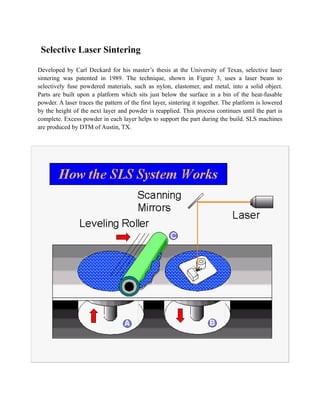
Developed by Carl Deckard for his master’s thesis at the University of Texas, selective laser
sintering was patented in 1989. The technique, shown in Figure 3, uses a laser beam to
selectively fuse powdered materials, such as nylon, elastomer, and metal, into a solid object.
Parts are built upon a platform which sits just below the surface in a bin of the heat-fusable
powder. A laser traces the pattern of the first layer, sintering it together. The platform is lowered
by the height of the next layer and powder is reapplied. This process continues until the part is
complete. Excess powder in each layer helps to support the part during the build. SLS machines
are produced by DTM of Austin, TX.
5. Technology description:
Stereolithography is an additive manufacturing process using a vat of liquid UV-curable
photopolymer "resin" and a UV laser to build parts a layer at a time. On each layer, the laser
beam traces a part cross-section pattern on the surface of the liquid resin. Exposure to the UV
laser light cures, or, solidifies the pattern traced on the resin and adheres it to the layer below.
* After a pattern has been traced, the SLA's elevator platform descends by a single layer
thickness, typically 0.05 mm to 0.15 mm. Then, a resin-filled blade sweeps across the part cross
section, re-coating it with fresh material. On this new liquid surface, the subsequent layer pattern
is traced, adhering to the previous layer. A complete 3-D part is formed by this process. After
building, parts are cleaned of excess resin by immersion in a chemical bath and then cured in a
UV oven.
* SLA requires the use of support structures to attach the part to the elevator platform and to
prevent certain geometry from not only deflecting due to gravity, but to also accurately hold the
2D cross sections in place such that they resist lateral pressure from the re-coater blade.Supports
are generated automatically during the preparation of 3D CAD models for use on the SlA
machine, although they may be manipulated manually. Supports must be removed from the
finished product manually; this is not true for all rapid prototyping technologies.
Highlights of Stereo Lithography Apparatus
* The first Rapid Prototyping technique and still the most widely used.
* Inexpensive compared to other techniques.
* Uses a light-sensitive liquid polymer.
* Requires post-curing since laser is not of high enough power to completely cure.
* Long-term curing can lead to warping.
* Parts are quite brittle and have a tacky surface.
* No milling step so accuracy in z can suffer.
* Support structures are typically required.
* Process is simple: There are no milling or masking steps required.
* Uncured material can be toxic. Ventilation is a must.
Introduction of Stereo Lithography Apparatus:
Stereo Lithography Apparatus (SLA), the first Rapid Prototyping process, was developed by 3D
Systems of Valencia, California, USA, founded in 1986. A vat of photosensitive resin contains a
vertically-moving platform. The part under construction is supported by the platform that moves
downward by a layer thickness (typically about 0.1 mm / 0.004 inches) for each layer. A laser
beam traces out the shape of each layer and hardens the photosensitive resin.
* The Stereo Lithography Apparatus (SLA) System overall arrangement
Stereo Lithography Apparatus ProcessThe sequence of steps for producing an Stereo
Lithography Apparatus (SLA) layer is shown in the following figures:
6. Uncured resin is removed and the model is post-cured to fully cure the resin. Because of the
layered process, the model has a surface composed of stair steps. Sanding can remove the stair
steps for a cosmetic finish. Model build orientation is important for stair stepping and build time.
In general, orienting the long axis of the model vertically takes longer but has minimal stair
steps. Orienting the long axis horizontally shortens build time but magnifies the stair steps. For
aesthetic purposes, the model can be primed and painted.
During fabrication, if extremities of the part become too weak, it may be necessary to use
supports to prop up the model. The supports can be generated by the program that creates the
slices, and the supports are only used for fabrication. The following three figures show why
supports are necessary: