
Recomendados
Recomendados
Mais conteúdo relacionado
Semelhante a Design Arduino Circuits & Schematics in Express SCH
Semelhante a Design Arduino Circuits & Schematics in Express SCH (20)
Último
Último (20)
Design Arduino Circuits & Schematics in Express SCH
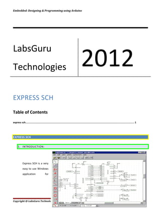
- 1. Embedded: Designing & Programming using Arduino EXPRESS SCH Table of Contents express sch......................................................................................................................................................... 1 EXPRESS SCH 1. INTRODUCTION: Express SCH is a very easy to use Windows application for Copyright @ LabsGuru Technologies Private Limited Page 1 LabsGuru Technologies 2012
- 2. Embedded: Designing & Programming using Arduino drawing schematics. While not required, we suggest that you draw a schematic for your circuit before designing the PC board 2. THE SIDE TOOLBAR: 1. THE TOP TOOLBAR: 2. BEGINNING A NEW SCHEMATIC: 1. Begin a new schematic by running Express SCH. 2. Select New from the File menu and then choose the desired page size, typically Letter - 8.5" x 11". It is best to set the page size to the same dimensions as the paper in your printer. By doing this, your schematic will be printed one-to-one. If you create a schematic with a larger page size than in your printer, the printed schematic is compressed to fit the printer. Copyright @ LabsGuru Technologies Private Limited Page 2
- 3. Embedded: Designing & Programming using Arduino 3. Fill in the text in the title block located in the lower right corner of the page. Double click on "Company Name", "Schematic Name" and "Designer's Name" to set these fields. 4. Finally, give your schematic a filename by selecting Save As from the File menu 5. Zooming and Panning: The easiest way to move around your layout is with the scroll wheel on the mouse. Turning the wheel zooms in and out. Pressing the wheel and dragging the mouse pans. 3. COMPONENTS AND SYMBOL You build a schematic by first placing components and symbols on the page and then wiring them together. In Express SCH, components and symbols are different. Components represent parts that you add to your circuit such as resistors and ICs. Symbols, such as these, are inserted into your schematic just like components. However they differ from components in that they don't have a physical part associated with them. Symbols are used to make electrical connections to common buses (such as ground) without having to draw wires. They are also used to make connections from one page of a schematic to another. Here is how they work: All symbols are assigned a Net Name (such as GND). Every symbol placed on a schematic with the same Net Name is electrically connected together. For example, every component pin that is wired to a ground symbol (which has the Net Name GND) is connected. 4. PLACING THE COMPONENT: Components represent parts that you will add to your circuit such as resistors and ICs. The easiest way to place components in your board layout is to use the Component Manager. Tip: Use the Find button to search for a component by its name. To place a component: 1. Click the button located on the top toolbar to display the Component Manager. Copyright @ LabsGuru Technologies Private Limited Page 3
- 4. Embedded: Designing & Programming using Arduino 2. Select one of these categories:· Library components -Components that are included with the program· Custom components - Components that you have drawn· Favorite components - Components or symbols that you have book-marked 3. From the list box, choose the item to insert. Note that the components list is organized by the prefixes:· Connector - connectors· IC - integrated circuits· Misc - batteries, buzzers and motors· Passive - resistors and capacitors· Semiconductors - transistors and diodes 4. Select how the component & its accompanying text are rotated by clicking one of or to flip right-to-left pick. 5. Press the Insert into schematic button, and then drag the component to the desired location. 6. Double click on the item just inserted to display its properties dialog box. Here you will assign the component its Part ID (such as R1 or U1) and Part name (such as 74LS00 or 3.3K). 7. PLACING THE SYMBOLS, PORTS: Symbols such as these are inserted into your schematic just like components. However symbols are different from components in that they don't have a physical part associated with them. To insert a symbol in to your schematic: 1. Select the button from the side toolbar. 2. From the top toolbar, choose the symbol in the list box 3. Move the mouse into the main window, press the left mouse button and drag the symbol to the desired location. 4. After placing a port symbol, assign it a Net Name. Do this by double clicking on it to display the Symbol properties dialog box. The port symbol shown here has been assigned the Net Name: 20 MHz 5. Keep in mind that all symbols given the same Net Name are electrically connected together on the schematic. 1. WIRING COMPONENTS: Copyright @ LabsGuru Technologies Private Limited Page 4
- 5. Embedded: Designing & Programming using Arduino From the side toolbar, select desired tab or press the W shortcut key. Move the mouse to the wire's first end point and click left. Typically you will start on the pin of a component. Drag the wire to the second end point, then click left again. Continue placing wire segments until you have reached the final end point. While dragging the wire, the Del key deletes the previous segment, the + and - keys zoom in and out, the G key toggles the snap-to-grid on and off, the Spacebar sets the wire, and the Esc key cancels it. To complete the operation, press the Spacebar or click right. 2. WORKING WITH WIRES: Wires themselves cannot be moved. The path of a wire is determined by the straight line between its two connections. Therefore, to move a wire, you need to connect it to something different or to move what it is connected to. Corners in wires allow them to bend. They are displayed as small square blocks at the ends of wires. A wire with two corners is shown here. When you print your schematic, the corners will not be visible. Corners can be dragged, inserted or deleted to change a wire's path. To insert a corner, select desired tab then click on the wire at the point where you want to insert it. To disconnect a wire and reconnect it elsewhere, select desired tab from the side toolbar. Next, click on the wire near the point you want to disconnect, and then drag the wire to a new pin. 3. CHECKING ERRORS: After completing your schematic, you should check it for errors before beginning your PC board layout. Run the command Check schematic for net list errors from the File menu. This will check for problems such as components that have not been assigned a Part ID, multiple components having the same Part ID, and missing pin numbers. This command also scans for wires that are not properly connected and tries to correct them. None of the wires leading to the LED seen here are connected. Wire 1 has not been dragged close enough to the LED's pin (shown as a dot). Though wire 2 ends on the LED, it does not attach to the right place. It needs to stop on the LED's pin. The gray corner markers at the ends of wires 1 and 2 indicate that they have not merged to the LED. When a wire is properly connected to a component's pin, the gray corner marker will disappear. The ground symbol (3) is also not connected. The pin on the ground symbol is too far away from the pin on the LED to make a connection. Copyright @ LabsGuru Technologies Private Limited Page 5
- 6. Embedded: Designing & Programming using Arduino 4. COPYING DELETING AND MOVING THE ITEMS: Express SCH uses standard Edit commands for Copy, Cut and Paste. To copy an item or several items, first select them. From the Edit menu choose Copy, and then choose Paste. Deleting items from your schematic is as easy as selecting them and pressing the Del key. There are three ways most items can be moved. Typically, items are moved by selecting and dragging them. They also can be moved with the arrow keys by selecting them and then pressing Ctrl-right, Ctrl-left, Ctrl-up or Ctrl-down. Alternately, an item can be moved by changing the coordinates set in its properties dialog box. Tip: To copy a group of items from one layout file to another, select and copy the items of interest into the clipboard. Load the second file into Express SCH and paste. It is not possible to copy items between two programs running at the same time. It is strongly recommended that you visually inspect your schematic for errors before designing your PCB. The Check schematic for net list errors command only identifies a few types of mistakes that you might have made. You should also make sure that all of your wires are properly connected to their components and other wires, because this command cannot fix all missed connections. 5. MAKING CUSTOM COMPONENT: Copyright @ LabsGuru Technologies Private Limited Page 6
- 7. Embedded: Designing & Programming using Arduino Copyright @ LabsGuru Technologies Private Limited Page 7