
Recomendados
Recomendados
Mais conteúdo relacionado
Mais procurados
Mais procurados (20)
Semelhante a Aircraft mechanical cable control system
Semelhante a Aircraft mechanical cable control system (20)
Mais de raj_sevak
Último
Último (20)
Aircraft mechanical cable control system
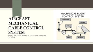
- 1. AIRCRAFT MECHANICAL CABLE CONTROL SYSTEM FLAPS, AILERON, RUDDER, ELEVATOR, TRIM TAB SYSTEM
- 2. INTRODUCTION Aircraft flight control systems consist of flight control surfaces, the respective cockpit controls, connecting linkages, and the necessary operating mechanisms to control an aircraft's direction in flight. Aircraft engine controls are also considered as flight controls as they change speed. They can be divided into three main groups: - Primary flight control - Secondary flight control - Auxilliary flight control
- 3. CONTROL SYSTEM Primary flight control - Elevator Control System - Aileron Control System - Rudder Control System Secondary flight control - Elevator Trim Tab System - Rudder and Aileron Trim Tab System Auxilliary flight control - Flap Control System - High Lift Devices
- 5. Elevator Control System An elevator is mounted on the back edge of the horizontal stabilizer on each side of the fin in the tail. They move up and down together. When the pilot pulls the stick backward, the elevators go up. Pushing the stick forward causes the elevators to go down. Raised elevators push down on the tail and cause the nose to pitch up. This makes the wings fly at a higher angle of attack which generates more lift and more drag. Many aircraft use a stabilator — a moveable horizontal stabilizer — in place of an elevator.
- 7. AILERON Control System Ailerons are mounted on the trailing edge of each wing near the wingtips, and move in opposite directions. When the pilot moves the stick left, or turns the wheel counter-clockwise, the left aileron goes up and the right aileron goes down. A raised aileron reduces lift on that wing and a lowered one increases lift, so moving the stick left causes the left wing to drop and the right wing to rise. This causes the plane to bank left and begin to turn to the left. Centering the stick returns the ailerons to neutral maintaining the bank angle. The plane will continue to turn until opposite aileron motion returns the bank angle to zero to fly straight.
- 9. RUDDER Control System The rudder is typically mounted on the back edge of the fin in the empennage. When the pilot pushes the left pedal, the rudder deflects left. Pushing the right pedal causes the rudder to deflect right. Deflecting the rudder right pushes the tail left and causes the nose to yaw right. Centering the rudder pedals returns the rudder to neutral and stops the yaw.
- 12. Elevator Trim Tab System Elevator trim balances the control force necessary to maintain the aerodynamic down force on the tail. When aircraft is flying, a lot of trim could be required to maintain the desired angle of attack. This mainly applies to slow flight, where maintaining a nose-up attitude requires a lot of trim. An important design parameter for aircraft is the stability of the aircraft when trimmed for level flight. Any disturbances such as gusts or turbulence will be damped over a short period of time and the aircraft will return to its level flight trimmed airspeed.
- 14. Rudder and Aileron Trim Tab System Trim doesn't only apply to the elevator, as there is also trim for the rudder and ailerons. The use of this is to counter the effects of slip stream, or to counter the effects of the centre of gravity being to one side. This can be caused by a larger weight on one side of the aircraft compared to the other, such as when one fuel tank has a lot more fuel in it than the other, or when there are heavier people on one side of the aircraft than the other.
- 17. Flap Control System Flaps are hinged surfaces on the trailing edge of the wings of a fixed-wing aircraft. As flaps are extended, the stalling speed of the aircraft is reduced. Flaps are also used on the leading edge of the wings of some high-speed jet aircraft, where they may be called Krueger flaps. Flaps increase the camber of the wing airfoil, thus raising the lift coefficient. This increase in lift coefficient allows the aircraft to generate a given amount of lift with a slower speed. Therefore, extending the flaps will reduce the stalling speed of an aircraft. They also increase drag which helps to slow the aircraft.
- 18. Types of flap systems: 1) Krueger flap: hinged flap on the leading edge. 2) Plain flap: rotates on a simple hinge. 3) Split flap: upper and lower surfaces are separate, the lower surface operates like a plain flap, but the upper surface stays immobile or moves only slightly. 4) Fowler flap: slides backwards before hinging downwards, thereby increasing both camber and chord, creating a larger wing surface better tuned for lower speeds. 5) Slotted flap: a slot (or gap) between the flap and the wing enables high pressure air from below the wing to re-energize the boundary layer over the flap. This helps the airflow to stay attached to the flap, delaying the stall. 6) Blown flaps: systems that blow engine air over the upper surface of the flap at certain angles to improve lift characteristics.
- 21. High Lift Devices Spoilers- On low drag aircraft like sailplanes, spoilers are used to disrupt airflow over the wing and greatly increase the amount of drag. This allows a glider pilot to lose altitude without gaining excessive airspeed. Spoilers are sometimes called "lift dumpers". Spoilers that can be used asymmetrically are called spoilerons and are able to affect an aircraft's roll.
- 22. High Lift Devices Slats- slats also known as Leading Edge Devices, are extensions to the front of a wing for lift augmentation, and are intended to reduce the stalling speed by altering the airflow over the wing. Slats may be fixed or retractable - fixed slats give excellent slow speed and STOL capabilities, but compromise higher speed performance. Retractable slats, as seen on most airliners, provide reduced stalling speed for take- off and landing, but are retracted for cruising.
- 23. High Lift Devices Leading edge cuffs- are a fixed aerodynamic device employed on fixed-wing aircraft to modify the airfoil used. They may be either factory-installed or, more commonly, an after-market modification. In most cases a leading edge cuff will “droop” the leading edge of the airfoil. This has the effect of causing the airflow to attach better to the upper surface of the wing at higher angles of attack, thus lowering stall speed. This allows lower approach speeds and shorter landing distances.
- 24. Thank you..
Notas do Editor
- NOTE: To change the image on this slide, select the picture and delete it. Then click the Pictures icon in the placeholder to insert your own image.