SlideShare uma empresa Scribd logo
1 de 50
The
original
wishing
machine
Future_Horizons “wishing machine” is actually a Radionic device and is now available as a
modified pyramid mind machine. Raymond Ebbeler author extraordinaire, inventor,
investor, an esoteric scientist and Pyramidologist has created the “ultimate wishing
machine” that allows humans and animals to accelerate the law of attraction to change
thought forms into reality
BioPhotonics is the electronic Magazine or had copy on how to construct a working pyramid
mind machine called the PyramiTronix Resonator that is constructed as a basic,
intermediate, and advanced stages for accelerating the law of attraction. The eZine is FREE
through the mobile app: http://apps.appypie.com/html5/the-wishing-machine
BIOPHOTONICS
Preface: Author’s Findings Supported by Wikipedia and Peer-Reviewed Research
The purpose for constructing a prototype model of the Great
Pyramid at Giza Egypt is to identify the shape as a resonant
cavity. According to Wikipedia a resonator is cavity and is
defined as:
A resonator is a device or system that exhibits resonance or resonant
behavior, that is, it naturally oscillates at some frequencies, called its
resonant frequencies, with greater amplitude than at others.
The oscillations in a resonator can be either electromagnetic or mechanical (including acoustic). Resonators are
used to either generate waves of specific frequencies or to select specific frequencies from a signal. Musical
instruments use acoustic resonators that produce sound waves of specific tones.
A Pyramid As A Cavity Resonator
A cavity resonator, usually used in reference to electromagnetic resonators, is one in which waves exist in a
hollow space inside the device. Acoustic cavity resonators, in which sound is produced by air vibrating in a
cavity with one opening, are known as Helmholtz resonators. A physical system can have as many resonant
frequencies as it has degrees of freedom; each degree of freedom can vibrate as a harmonic oscillator. Systems
with one degree of freedom, such as a mass on a spring, pendulums, balance wheels, and LC tuned circuits have
one resonant frequency. Systems with two degrees of freedom, such as coupled pendulums and resonant
transformers can have two resonant frequencies. A crystal lattice composed of N atoms bound together can have
N resonant frequencies. As the number of coupled harmonic oscillators grows, the time it takes to transfer
energy from one to the next becomes significant. The vibrations in them begin to travel through the coupled
harmonic oscillators in waves, from one oscillator to the next. The term resonator is most often used for a
homogeneous object in which vibrations travel as waves, at an approximately constant velocity, bouncing back
and forth between the sides of the resonator. The material of the resonator, through which the waves flow, can
be viewed as being made of millions of coupled moving parts (such as atoms). Therefore they can have millions
of resonant frequencies, although only a few may be used in practical resonators. The oppositely moving waves
interfere with each other to create a pattern of standing waves in the resonator. If the distance between the sides
is , the length of a round trip is . To cause resonance, the phase of a sinusoidal wave after a round trip must
be equal to the initial phase so the waves self-reinforce. The condition for resonance in a resonator is that the
round trip distance, , is equal to an integral number of wavelengths of the wave:
If the velocity of a wave is , the frequency is so the resonant frequencies are:
So the resonant frequencies of resonators, called normal modes, are equally spaced multiples (harmonics) of a
lowest frequency called the fundamental frequency. The above analysis assumes the medium inside the
resonator is homogeneous, so the waves travel at a constant speed, and that the shape of the resonator is
rectilinear. If the resonator is inhomogeneous or has a nonrectilinear shape, like a circular drumhead or a
cylindrical microwave cavity, the resonant frequencies may not occur at equally spaced multiples of the
fundamental frequency. They are then called overtones instead of harmonics. There may be several such series
of resonant frequencies in a single resonator, corresponding to different modes of vibration.
Because of the universe
and cosmos as a space-
time continuum -- a
region for aether to be
abundant for all to harness
is the Great Pyramid
which also incorporates in
its sides and angles the
means for creating a
highly sophisticated map
projection of the northern
geo-hemisphere.
Further along with the other two Giza pyramids replicates the exact positions of the three stars in the
Constellation Orion where is an example of The Golden Spiral, whereby the three pyramids and the Sphinx are
interlocked and thus situated by design.
The PyramiTroniX Resonator similarly introduces the shape for the invention
which accelerates the Law of Attraction as a scaled down version for the
“pyramid housing assembly.”
The purpose for this housing is to capture the electron (photon) discharge
abundant in the aether which couples with the bio-photons of an individual's
brain and body.
The present invention provides a method and apparatus that addresses "putative" energy fields or bio fields
which have denied measurement based on the concept that humans are infused with a subtle energy having 70
different names such as chi, ki, prana, life force, etc. However, in theoretical physics, scalar field theory can
refer to a classical or quantum theory of scalar fields. A field which is invariant under any Lorentz
transformation is called a "scalar", in contrast to a vector or tensor field. The quanta of the quantized scalar field
are spin-zero particles, and as such are bosons. The only fundamental scalar field that has been observed in
nature is the Higgs field. However, scalar fields appear in the effective field theory descriptions of many
physical phenomena. An example is the pion, which is actually a "pseudoscalar", which means it is not invariant
under parity transformations which invert the spatial directions, distinguishing it from a true scalar, which is
parity-invariant. Because of the relative simplicity of the mathematics involved, scalar fields are often the first
field introduced to a student of classical or quantum field theory. In particle physics, a pion (or a pi meson,
denoted with the Greek letter pi: π) is any of three subatomic particles: π0, π+, and π−. Each pion consists of a
quark and an antiquark and is therefore a meson. Pions are the lightest mesons (and, more generally, the lightest
hadrons), because they are composed of the lightest quarks (the u and d quarks). They are unstable, with the
charged pions π+ and π− decaying with a mean lifetime of 26 nanoseconds (2.6×10⁻⁸
seconds), and the neutral
pion π0 decaying with a much shorter lifetime of 8.4×10⁻¹⁷
seconds. Charged pions most often decay into muons
and muon neutrinos, and neutral pions into gamma rays.
Nonetheless, since biofields have not been measured by conventional instruments and that neither the external
field nor their therapeutic effects have been robustly scientifically demonstrated as a biophysical process, the
objective is to design a method and apparatus that focuses on the interactions of the brain (consciousness) and
body (cardiac) to amplify emotional, mental, social, and spiritual parameters of human growth and self-
development.
Non-invasive measurement can determine various changes in biological system s which includes the chemical
analysis of blood, urine, and other processes relative to bio-photonic discharge usually considered the waste by-
product of metabolism.
Previously, infrared photon energy was used since the kinetic energy of thermal movement of molecules is E =
0.132 eV (electron volts) at 9,350 nm (nanometers). In contrast is the 1.67 - 3.41 eV (electron volts) of visible
photons necessary for cells to regenerate regarding bio-photon emissions (BPE) as natural processes.
Bearden (1995) determined 1kg of mass was equivalent to 17.053 X 10 ^ 50 and served as an "action switch" as
a small as a quantum as defined by Planck's constant divided by four. He de-differentiated an infected cell
(DND) and it was the de-differentiation process that indicated the DNA as a "time-reversal" potential at its
previous state of health and wellness. However a problem observed is between energy and the energy density
flow relative to Einstein's E=MC ^2. He related that electromagnetic energy trapped in space is equal to c ^2
(time squared) since energy can be transformed from one state to another state.
However, a reference to Whitaker's (1903) seminal paper "On the partial differentiation equation of
mathematical physics" indicates that scalar potentials can be decompositioned into a harmonic series of bio-
directional electromagnetic wave pairs. Of significance is that each wave pair consists of a wave and its phase
conjugate (anti-wave) observed as a "virtual" or phantom effect. By the "distortion correction theorem" of non-
linear optics (not yet in existence til 1970) was each wave pair (wave, anti-wave) as a superposition for space
(wave) and time (anti-wave). Therefore each wave pair appears as a standing wave where each point as (E )
energy of the wave and (-E) N-energy of the anti-wave simultaneously superimpose with each other. In
superposition (E, -E); individual vectors do not cancel or cease to exist since the wave pair passes through space
as observed by the observer. For this to occur, an observation time is needed to detect the "observation effect"
as E and -E. However, it is the E(T) and -E(T), the "observation time differentiation" which removes time so
that the observer will observe a zero an d a non-E field comprised of E + (-E) = 0. Thus the scalar field densities
can b e summed at any point and a gravitational standing wave is superposed as the true phase conjugate
replicated (time-reversal of wave pairs) and the electromagnetic field is converted to gravity. Whitaker
indicated that the wave pair include s photons/anti-photons as pairs -- a spin 2 entities called gravitons, not
individual photon in the 4th dimension (time). Whereas, E(T) and -E(T) did not cancel in the 3rd dimension
(space).
Mind, Body, & Spirit Development The practical scalability of the PyramiTroniX Resonator
as a full-scale model can now evolve as a trihierarchical stage of development regarding mind, body and
spiritual.
Contemporary neuroscience research addresses the existence of algorithms for all sensory transduction
necessary as brain-specific coding referred to as "intrinsic data fields" (IDF).
Direct stimulation of these codes are within the human temporal or limbic cortices with application of
electromagnetic patterns which usually require high energy levels. However, a scaled down process is coupling
a narrow band whose frequencies range from 1 - 15 cycles per second HZ (Hertz).
Although the resultant vector summation of the E field is a zero vector, the scalar field densities can be summed
at any point thus “non-localization.” Of particular interest is Dirac (1929) who postulated a "quantum theory"
for the electron and predicted anti particles and electrons or positrons through the process of " positron
annihilation" where the pairing of electrons produce a photon and the new area of research became known as
"Quantum Electrodynamics" (QED).
Thus non-localization was not an instantaneous connection across space, but rather time which coupled separate
systems where no physical (phantom) activity or interaction occurs at the speed of light...but thought.
Since non-localization was based on deBroglie-Boem's theory which occurs when an electric current was passed
through hydrogen gas, a radiated light, when dispersed through a prism produced a line spectrum and supported
Heisenberg's Uncertainty Principle based on energy and time as a functional relationship. It further purports that
if energy was sufficient to penetrate a barrier, the electron could "tunnel" through that barrier by sharing
"surplus" (free) energy based on superposition when the electron is a wave function.
Since neurons can be excited by externally applied time-varying electromagnetic fields, the pulse current I(T),
the point source to where a cell could be positioned above the forehead (pineal gland) an/or adjacent to the head
(temporal lobe s) activate the E-field in tissue based on
Faraday's law"
V x E= alphaB / alpha T where B is the magnetic field produced by the coil based on
Biot-Savart Law
B (r1, t) = mu0 / 4 pi => d/r ^1 X (r-r ^1) / 1r - t (1/3)
These laws are amenable to scientific method as a non-invasive imaging process where the brain as a charge
point can be measured as a field outside the head indicative of metabolic and hemo (blood) dynamics. The
conventional neuroscience provides evidence-based research for multiple techniques regarding imaging.
Raymond W. Ebbeler, Ph.D. (Candidate; on Sabbatical)
Health Psychology, Walden University
The Wishing Machine
This amazing machine is actually just a type of “Psionic” amplifier that works using a direct link to your own
mind. It essentially amplifies your intent or wish and can help to materialize it into your reality. The machine is
simply a tool and the real power actually comes from the person using it so the more focused your mind and
willpower is the better your results will be.
This technology has been around for many years and was successfully tested many times even in
laboratory conditions. Many people thought it was complete nonsense but now conventional science is
finally catching up. Some researchers now believe that it is a Quantum Mechanics effect that allows the
machine to work. A thought experiment invented by Albert Einstein, Boris Podolsky, and Nathan Rosen
back in the late 1930's has now begun to scientifically substantiate much of the psychic and Psionic
phenomenon. It is a sort of bizarre loophole in quantum physics known as the EPR (Einstein-Podolsky-
Rosen) effect that seems to tell us that our world is put together in such a way that an event going on in a
distant galaxy or in the mind of a friend across town is also going on in some analogous way in our own
mind simultaneously. The experiment is a bit complex and rather difficult to explain but here it is: The
experiment involves what physicists call a two particle system of zero spin.
This means that you have two particles, such as two electrons, one spinning one way and the other
spinning in exactly the opposite way so that the spin of each of the electrons cancels the other out. One
spins right while the other spins left or one spins up while the other spins down. In the experiment the
two particles are separated electrically so that their spins should not have an effect on one another. Now
comes the strange part. Physicists were able to affect the spin of one of the electrons randomly using a
magnetic field and found that the other electron seemed to know instantly that this occurred and it
reverses its own spin to maintain equilibrium of spin cancellation.
This experiment tends to confirm that there is a universal connectedness with all things within our
world. And that information about any part of the whole is instantly available to any single part! This
strange connectedness proven by the EPR effect has a mathematical proof known as Bell's theorem,
which was published in 1964 by J .S. Bell, a physicist at the European organization for nuclear research
(CERN) in Switzerland. Bells theorem implies that at a fundamental level the "separate parts" of the
universe are connected in an intimate and immediate way. Another amazing part of this is the fact that
this type of informational transfer if you will takes place instantaneously everywhere in the universe.
This has some incredible and far reaching implications in the way our reality actually works. The
experiment gives confirmation to the belief that all matter in the known universe exhibits a universal
connectedness and that information is available and accessible to anything or anyone who knows the
secret of accessing it. This is like a universal collective unconscious. This also means that the
subconscious minds of all people are also collectively linked on some level together and to the rest of
the universe. The same apparently goes for all physical matter.
FutureHorizons
Dr. Raymond Brown and the Underwater Pyramid
In 1970, Dr. Ray Brown, a naturopathic practitioner from Mesa, Arizona, was scuba diving with friends near the Bari
islands, Bahamas, in an area 20 miles from the edge of a submarine drop-off called the Tongue of the Ocean.
During the dive, Brown became separated from his companions, and in trying to rejoin them, suddenly saw a strange
pyramid shape looming up against the aquamarine light. The pyramid was situated 22 fathoms down, stood 120 feet
high, with only 90 feet projecting out of the sea floor shifting sands. Brown was at first struck by how smooth and mirror-
like the stone surface of the structure was, with the joints between the individual blocks almost indiscernible.
Swimming about the capstone, which the Arizona diver thought looked like lapis lazuli, he discovered an entranceway
and decided to explore further. Passing along a narrow hallway, Brown finally came to a small rectangular room with a
pyramid-shaped ceiling. What was amazing was that the room contained no algae or coral growing on the inner walls.
They were completely spotless.
In addition, though Brown had brought no flashlight, he could nevertheless see everything in the room perfectly.
It was very bright and well lit, but no direct light source was visible. Brown's attention was drawn to a brassy metallic rod
3 inches in diameter hanging down from the apex of the center, and at its end was attached a many-faceted red gem,
which came to a point. Directly below the rod and gem, sitting in the middle of the room was a stand of carved stone
topped by a stone plate with scrolled ends.
On the plate rested a pair of carved metal bronze-colored hands, life-sized, which appeared blackened and burnt, as if
having been subjected to tremendous heat. Nestled in the hands, and situated 4 feet directly below the ceiling rod gem
point, was a crystal sphere 3-1/2 inches in diameter.
Brown first attempted to pry loose the ceiling rod and red gemstone, but neither would budge. Turning back to the crystal
sphere he found it easily separated from the bronze hand holders, and left the pyramid with it. As he departed, Brown
felt a presence, and heard a voice from somewhere telling him never to return.
Fearing that his unusual prize might be confiscated as salvage-treasure by the U.S. government, Dr. Brown did not
disclose the existence of the strange crystal or his experiences until 1975, when he exhibited the crystal for the first time.
He displayed the crystal only a half dozen times, but each time witnesses have seen or have been sensitive to strange
phenomena directly associated with it.
Deep inside the crystal form one gazes upon three pyramid images, one in front of the other, in decreasing sizes. Some,
entering into a meditative or alpha brainwave state of consciousness, are able to clearly see a fourth pyramid, in the
foreground of the other three.
The significance of the image may have been hinted at by psychic Elizabeth Bacon of New York. In a trance reading on
the mysterious sphere, she received the message that the object had once belonged to Thoth, the Egyptian god who
ages ago buried a secret vault of knowledge at Giza, near the three great Pyramids there. Do the positions of the three
pyramid images in the crystal hold a key to finding a fourth, as yet unfound subterranean pyramid, that is the fabled Hall
of Records?
From the side, the internal images dissolve into thousands of tiny fracture lines, and Brown feels these may be electrical
in nature, like some form of microscopic circuitry. From still another angle, and under special conditions, many witnesses
have been able to see a large single human eye staring out serenely at them. Photographs of this eye have also been
taken.
Like the mysterious crystal skull of Central America, Dr. Brown's crystal sphere is the source of a variety of paranormal
events. People have felt breezes of ionic winds blowing close to it; cold and warm layers surround it at various distances;
other witnesses have been phantom lights, heard voices, or felt strange tingling sensations around it.
A compass needle placed next to the sphere will spin counterclockwise, then begin turning in the opposite direction
when moved only two inches away.
Metals are temporarily magnetized in close contact with it. There are even recorded instances where one person has
been temporarily healed of an ailment by touching the crystal sphere, but then the next person to come into its range
took on the symptoms of the ailment of the other person, as if the crystal could draw out and then activate human
disorders at will.
Just what the purpose of the crystal sphere was, and what role it once played in the enigmatic instrument Brown found
inside the sunken Bahaman pyramid, remains a mystery, though of course there are some interesting possibilities.
One idea proposed is that the sunken pyramid once attracted, accumulated and generated cosmic forces.
The suspended rod may have conducted forces accumulated in the capstone; the faceted red gem at its end
concentrated and projected the energy to the crystal sphere below it; and the burnt and blackened hands, showing the
evidence of an energy transfer, probably amplified the release of energies; while the crystal sphere acted as the tuner
and broadcaster of the energies.
All that we know for certain is that the crystal sphere Dr. Brown retrieved from this system is by itself testimony to a
most sophisticated technology, for as experts at the Smithsonian Institute in Washington noted, the technology for
cutting quartz stone to the perfection exhibited in the crystal sphere was not accomplished by our civilization until after
1900.
Is It Alien Technology? Another Variant Is The Telepathic Pyramid
The painting also shows the exact shape and relative size of the pyramid, as well as the manner it was held by
the being. The colour scheme of the pyramid’s surface, as well as shadows and illustration of walls’
transparency, is conveying the impression that Daniela got when looking at the working pyramid.
Fig. C2. A photograph of the pyramid
Shown is a prototype of this device built in Poland, but not made operational. More details about the purpose,
operation, and theory behind this device is provided in treatise [7], in chapter G of monographs [3] & [3/2], as
well as in chapter N of monographs [1/2] & [1/3].
Research on the prototype completed by Daniela indicated that after an alternating current of high frequency is
supplied to the device from an external source (e.g. from a radio) the pyramid produces some kind of telepathic
signal. However, her prototype still hides some construction errors which make it impossible to operate
according to the original specification of the giver. To eliminate these errors, further theoretical research and
physical development needs to be carried out.
 (Top) The side view of the whole pyramid. The device is held by myself (Dr Jan Pajak) in a manner
similar as the little being with blue eyes held it in his hands. During such holding the biofield of the user
infiltrates through the active space of the device. Because this bio-field carries the thoughts of the user,
it modifies with these thoughts the state of the optical interference cavity. In turn the modifications of this
optical interference cavity are imposed onto the electrical oscillations from the pyramid’s resonator, thus
modulating these oscillations.
After the modulation into magnetic vibrations these thoughts are emitted into space from which they can
be intercepted by another similar device. After being intercepted these thoughts are demodulated and
superimposed on the biofield of another user, thus appearing in his/her mind as another set of thoughts
imposed on his/her own.
 (Bottom) The inner components of the pyramid. The casing (hat) is visible from underneath after being
put aside on the right.
Fig. C3. The general shape, design, and main components of the pyramid
This illustration is prepared as if all the elements were transparent, i.e. through subsequent components the
elements, shapes, and connections placed behind them are visible. It represents a repetition of Figure N2 from
monographs [1/3] and [1/2], and Figure 1 from treatise [7].
This device is shaped as a pyramid of around 27.5 [cm] high. Its wiring and main components are hermetically
enclosed inside a pyramidal casing made of perspex or glass. The casing hosts: a copper frame (F) shaped like
a pyramid and aligning each corner of the casing, a conical coil © also made of a copper wire, four aluminium
disks (D1), (D2), (D3), (D4) attached to the side walls of the pyramidal casing - one of them (D1) should have a
small hole in the centre, quartz crystal (Q) placed at ¼ of the height, phial (T) placed in the centre of the base,
two inductors (I1) and (I2), and four cascades of mirrors (M1), (M2), (M3), (M4) placed in four corners of the
base. All these components should not touch each other, although they should be electrically connected
together according to the original instruction.
Their electrical properties should fulfil the condition of “harmonic” proportions.
The phial (T) should be half filled with ordinary kitchen salt, half with mercury. It is recommended that it should
work under a vacuum. Both inductors (I1) and (I2) are made of small bar magnets with copper wiring tightly
winded around them. Each cascade of mirrors (M) is made of three small mirrors of descending heights. The
copper frame (F) is simply eight pieces of copper wire joined together so that they form the shape of a pyramid.
It is recommended that the whole pyramid should be under a vacuum.
Fig. D1. The electrical diagram which illustrates the basic circuits and connections
existing in the pyramid
It is reproduced from Figure N3 of monograph [1/3]. The continuous lines indicate the connections that were
described to Daniela in the original disclosure. The broken lines indicate electrical connections which were not
included in the original disclosure, but the existence of which is explained by theories described in chapter D of
this treatise (chapter D explains the phenomena, principles, and basic circuits involved in the pyramid’s
operation).
The below diagram illustrates my knowledge about the operation of this device at the time of writing this treatise
(the further theoretical research which I continually carry out, combined with experiments which hopefully will be
inspired by this treatise and may be completed by readers, in future may introduce some improvements to this
diagram).
Names of subsequent components of this pyramid are reflecting the use of this device as a telepathyser. The
corresponding names of the same components for the operation of the pyramid as a telekinetic battery are
explained in subsection D2.4. The pyramid is composed of the following main circuits and individual
components: (1) receiving antenna for telepathic waves. It is composed of the quartz crystal (Q) placed in the
focal point of the telepathic resonance cavity that is formed from four aluminium disks (D1, D2, ... D4). (2)
The modulating and demodulating circuit (resonator - R). It is composed of such components as inductors (I1)
and (I2), a glowing tube (T), and a vacuum capacitor. The capacitor is formed out of two types of “plates” (which
differ in shapes), separated from each other with a layer of vacuum (or air). The first of these “plates” is formed
from four aluminium disks (D1, D2, ... D4) connected together.
The second “plate” of the capacitor is formed from a conical coil © and a frame (F) connected to it. In order to
increase the communicativeness of this diagram, the resonator circuit is marked with a dotted line ®. (3) The
optical interference chamber/cavity which functions as an “inouter” for thoughts. It is composed of: a glowing
tube (T) and not shown here four cascades of mirrors (M) which cooperate with this tube. (4) Emitting antenna
which forms the telepathic waves and sends them throughout counter-world. It has a shape of a conical coil ©.
Fig. D2. A revealing device. It represents a simplified, self-defense version of telepathic
telescopes
Such devices, if completed, would enable us to see our cosmic parasites which so-far successfully were hiding
from our sight by entering a state of telekinetic flickering. More thoroughly the design of this device is described
in treatise [7B].
A state of telekinetic flickering is accomplished by switching on a sequence of fast pulses of the telekinetic field.
Each such a pulse is turning the object that is wrapped into this field into a transparent energy pattern or cloud.
But between these pulses the object remains material and visible. Therefore, if such a flickering is fast enough,
the object becomes unnoticeable for our eyes, similarly as in our motion pictures the flickering of individual
frames becomes invisible for us. But each pulse of the telekinetic field can be intercepted by the device showed
here, and revealed as a glowing shape. Therefore the revealing device illustrated here allows us to see normally
invisible UFOnauts and their vehicles.
They appear as glowing figures at the device’s electromagnetic screen (s).
As this is the case with optical telescopes, also the revealing devices are composed of a main tube (t), on which
all other components are to be assembled. At the frontal part of this tube a focusing magnetic lens (f) is
assembled. At the rear part of the same tube the viewing magnetic lens (v) is assembled. In a simplified, self-
defence version of the telepathic telescopes called here “revealing devices”, such lenses (f) and (v) are simply
permanent magnets (or permanent electromagnets which use DC).
In centre of the tube an electromagnetic screen (s) is formed - see the dotted plane extending across the tube
(t). This screen is composed of a collision surface and the athwart electrostatic field. The collision surface (s) is
formed by the two magnetic fields bumping into each other with their magnetic poles (O) which represent an
“outlet” for flow of counter-matter (for the notation of magnetic polarity used by present physicists: O=N).
The athwart electrostatic field which is spreading from two thin electrodes (e) extending along the peripherals of
the collision surface and placed at the opposite side of the tube (t). The whole interior of the tube must be filled
up with an extraction glow generating substance (g).
Back to Contents
Appendixes
Appendix Z1
List of illustrations of the treatise [7/2] “Pyramid of thoughts” (ISBN 0-9583727-1-3)
Because copies of this treatise [7/2] are to be available via Internet, where the inclusion of illustrations may pose
a technical problem, in this listing of illustrations additional information is provided which indicates which of the
publications listed i chapter G also contains a given Figure (most of publications listed in chapter G was supplied
to the National Library of Poland, to all libraries of province capitols in Poland, and also to the main libraries of
almost all higher education institutions in Poland, not mentioning similar libraries in New Zealand and in several
other countries outside Poland).
For example the symbol [1/3]-F1 means that a give illustration is also included into the monograph [1/3] as
Figure F1. The use of symbol ~ indicates either an older version of the same illustration, or illustration very
similar, while the use of symbol ¨ indicates a colour print of a given photograph. Note that in the following pairs of
monographs very similar illustrations were used: [1/2] & [1/3], [3] & [3/2], [5] & [5/2], [5/3] & [5/4], [6] & [6/2]. Also
the Polish and other language versions of the same publications have identical illustrations, e.g.: [5/2] & [5/2E],
or [7], [7E] & [7I].
Treatise [7/2] includes 29 illustrations, which in the printed versions of this treatise are arranged into 12 Figures,
a title page, and 2 “about the authors” pages. In Internet each of these illustrations is available as a separate
item. Symbols assigned to individual illustrations/items reflect their location on a given Figure. Thus illustrations
the symbol of which includes letter “H” are placed in the higher row of a Figure, while illustrations with letter “L”
are placed in the lower row of a Figure. Within a given row, symbols “l, m, r” mean the location on left, in the
middle, or on right.
In turn symbols “a, b, c”, or “1, 2, 3, 4”, indicate a writing-type order within a given Figure.
 Fig. A1. The smallest Magnocraft - type K3. [4B]-B1, [5/2]-19, [5/4]-G2, [1/3]~F1, [6/2]-10,
o (A1a) General design and components of K3 type Magnocraft. [1/3]-F1, [1E]-B1, [1I]B1, [3/2]~H1,
o (A1b) Side view of the smallest magnecraft type K3. [1/3]-F1, [1E]-G4, [1I]-G4, [5/4]-G2,
o (A1c) Twin-chamber capsule composed of two oscillatory chambers. [1/3]-C5, [1E]-F4, [1I]-F4,
[2]C4, [3/2]-F5,
 Fig. A2. Flying arrangements formed by magnocraft. [1E]-G6, [1I]-G6, [2]-D3, [3/2]-H3, [5/3]-F5, [6/2]-12,
[4B]-B2,
 Fig. A3. Scorch marks left on the ground by landed UFOs.
o (A3H) Connection between a vehicle’s height and a shape of landing site. [1/3]-F33, [1I]~G38,
[5/2]-23, [5/3]-F3,
o (A3L) Photographs of landing sites scorched by single UFOs. [1/3]-P1, [5/2]~33, [5/3]~G9,
o (A3Ll) Two concentric rings. [1/3]-P1, [1E]-M7/H, [1I]-K1, [5/2]-33ª, [5/3]-G9, [5/4]-H9a,
o (A3Lm) A ring with central scorching. [1/3]-P1, [1E]-M2/H, [5/2]-33b, [5/3]-G9, [5/4]-H9b,
o (A3Lr) A ring with a flange. [1/3]-P1, [5/2]-33c, [5/3]-G9, [5/4]H9c,
 Fig. A4. The Tapanui crater where around 7 UFO vehicles exploded in 1178 AD. [1/3]-P4,
o (A4H) A photograph of the Tapanui crater’s eastern slope. [1/3]-P4, [1E]-M19d, [1I]¨K4/L, [5/2]2,
[5/3]-A2, [5/4]-A2,
o (A4L) Comparison of similarities between Tapanui and Tunguska. [1/3]-P5, [1E]-M30, [5/2]-8,
[5/3]-C6, [5/4]-C6
 Fig. A5. Examples of underground tunnels evaporated in rocks by UFOs. [1/3]-P6, [5/2]~32, [6/2]~21,
(#1-#3) Photos of tunnels evaporated in rocks by UFOs. [1/3]-P6, [4B]-B4,
o (A5_1) Cocklebiddy Cave, Australia. [1E]-M18, [1I]¨K3/1, [5/2]-32/2, [5/3]-G8, [6/2]-21/2, [4B]-
B4b,
o (A5_2) Deer Cave, Borneo, Malaysia. [1/3]-P6, [4B]-B4/L,
o (A5_3) Tunnel Morona-Santiago, Ecuador. [1E]-M17, [1I]¨K3/2ª, [5/2]-32/1, [5/3]-G8, [6/2]-21/1,
[4B]-B4a,
o (A5_4) Principles of formation of underground tunnels by UFOs. [1/3]-F31, [4B]-B3, [1E]~G36,
[1I]~G36,
 Fig. B1. The 550 million year-old imprint of human foot. [1/3]-O32,
 Fig. B2. An old church painting on the Crucifixion supervised by UFOs. see description under Fig. B2,
 Fig. C1. The little white being with blue eyes holding the pyramid. this illustration is unique for [7/2],
 Fig. C2. A photograph of the pyramid described here. [1/3]-N1, [3/2]-G1, [5/3]-F8, [7]~2,
o (C2H) Dr Jan Pajak holding the pyramid. [1/3]-N1, [3/2]-G1, [5/3]-F8, [7]~2,
o (C2L) A photograph of the pyramid’s interior. [1/3]-N1, [3/2]-G1, [5/3]-F8, [7]~2,
 Fig. C3. The internal design of the pyramid described here. [1/3]-N2, [3/2]-G2, [7]-1,
 Fig. D1. The electrical circuitry (connections) of the pyramid described here. [1/3]-N3, [3/2]-G3, Fig. D2. A
revealing device. [7B]-1/H.
Independently from Figures listed above, treatise [7/2] uses also one drawing on the front page which represents
a repetition of illustration from Fig. C1, and also includes passport-type photographs of both authors included
into descriptions from chapter H “About Authors”.
Back to Contents
Integrating the Pyramid Cavity and the Coupling
Coefficient of Resonators: The Wishing Machine
Schematic
Wikipedia defines a coupling coefficient of resonators as having a dimensionless value that characterizes
interaction of two resonators: in this case…the Pyramid Cavity and the Wishing Machine Schematic as
Coupling coefficients which are used in resonator filter theory.
Since resonators may be both electromagnetic and acoustic the coupling coefficients are synchronized together
with resonant frequencies within the alpha – theta range such that the external quality factors of resonators are
better generalized parameters of filters. In order to adjust the frequency response of the filter it is sufficient to
optimize only these generalized parameters that are specific to the Pi (3.14) and Phi (1.618) ratios found in
nature.
Evolution of the term Resonator
Coupling coefficient considered as a positive constant
Earlier well-known definitions of the coupling coefficient of resonators are given in monograph by G. Matthaei
et al.[2]
Note that these definitions are approximate because they were formulated in the assumption that the
coupling between resonators is sufficiently small. However, the coupling coefficient for the case of two equal
resonators such as the scaled down model of the Great Pyramid and a Tesla Coil is a positive constant as a
longitudinal or standing wave that emits a scalar energy
The Pyramid cavity is a nodal representation for information transfer which characterizes
interaction of “contextual” resonators as a resonant frequency range: Alpha – Theta
The PyramiTroniX Resonator will be a conduit for focusing thought to change one’s realty using the mind-
body-spirit triad which is the ultimate spiritual experience of transcendence.
Bandpass filters with cross couplings
The Pyramidal Cell In the
Human Brain and Body
Exoteric versus Esoteric Science
As an exoteric scientist I was interested in using Psychoneuroimmunology to emphasize
biophotonic emission, while I also was an esoteric scientist / pyramidologist and adhered to the
discipline of Radionics as an innovative approach to integrating the mind-body problem in health
psychology. I found that Psychoneuroimmunology actually addressed the overlap in the health and
wellness industry as an alternative medicine that the American Medical Association (AMA) regards
as a pseudoscience that I found it necessary to start a non-profit: Black Box Energies & Research.
Unfortunately, the web site was removed and I had to go underground to do research on Radionics.
Having traveled to the United Kingdom ten years previously in 1988 as an exchange student in
World Art 101; I attended a conference held by the Radionics society in Oxford, England.
Basic Evolution of Radionics: The Human-Machine Interface & the Wishing Machine Circuit
The Heironymus Machine SymbolicsActual
https://youtu.be/uYL3tQborDw
Radionics: United States & United Kingdom
From Wikipedia, the free encyclopedia
Jump to: navigation, search
Contemporary Radionic instruments
Radionics is an alternative medicine that claims disease can be diagnosed
and treated with a kind of energy similar to radio waves.[1]
The concept
behind radionics originated in the early 1900s with Albert Abrams (1864–
1924), who became a millionaire by leasing radionic machines which he
designed himself.[1]
Radionics contradicts some principles of physics and
biology and so is commonly considered pseudoscience.[2]
The United States Food and Drug Administration does not recognize any legitimate medical uses for such
devices.[1][2][3]
The Wheatsone Bridge as a Substitute for the Radionic Circuit
A Wheatstone bridge is an electrical circuit used to measure an unknown electrical resistance by balancing two
legs of a bridge circuit, one leg of which includes the unknown component. Its operation is similar to the
original potentiometer. It was invented by Samuel Hunter Christie in 1833 and improved and popularized by Sir
Charles Wheatstone in 1843. One of the Wheatstone bridge’s initial uses was for the purpose of soils analysis
and comparison.[1]
Operation
In the figure, is the unknown resistance to be measured; , and are resistors of known resistance and
the resistance of is adjustable. If the ratio of the two resistances in the known leg is equal to the ratio
of the two in the unknown leg , then the voltage between the two midpoints (B and D) will be zero and
no current will flow through the galvanometer . If the bridge is unbalanced, the direction of the current
indicates whether is too high or too low. is varied until there is no current through the galvanometer,
which then reads zero.
Detecting zero current with a galvanometer can be done to extremely high accuracy. Therefore, if , and
are known to high precision, then can be measured to high precision. Very small changes in disrupt the
balance and are readily detected.
At the point of balance, the ratio of
Alternatively, if , , and are known, but is not adjustable, the voltage difference across or current flow
through the meter can be used to calculate the value of , using Kirchhoff’s circuit laws (also known as
Kirchhoff’s rules). This setup is frequently used in strain gauge and resistance thermometer measurements, as it
is usually faster to read a voltage level off a meter than to adjust a resistance to zero the voltage.
The 555 Timer Integrated Chip
The 555 timer IC is an integrated circuit (chip) used in a variety of
timer, pulse generation, and oscillator applications. The 555 can be
used to provide time delays, as an oscillator, and as a flip-flop element.
Derivatives provide up to four timing circuits in one package.
Introduced in 1971 by American company Signetics, the 555 is still in
widespread use due to its ease of use, low price, and stability. It is now
made by many companies in the original bipolar and also in low-power
CMOS types. As of 2003, it was estimated that 1 billion units are
manufactured every year.[1]A
Design
Internal schematic
Internal schematic (CMOS version)
The IC was designed in 1971 by Hans Camenzind under contract to Signetics, which was later acquired by
Dutch company Philips Semiconductors (now NXP).
Depending on the manufacturer, the standard 555 package includes 25 transistors, 2 diodes and 15 resistors on a
silicon chip installed in an 8-pin mini dual-in-line package (DIP-8).[2]
Variants available include the 556 (a 14-
pin DIP combining two 555s on one chip), and the two 558 & 559s (both a 16-pin DIP combining four slightly
modified 555s with DIS & THR connected internally, and TR is falling edge sensitive instead of level
sensitive).
The NE555 parts were commercial temperature range, 0 °C to +70 °C, and the SE555 part number designated
the military temperature range, −55 °C to +125 °C. These were available in both high-reliability metal can (T
package) and inexpensive epoxy plastic (V package) packages. Thus the full part numbers were NE555V,
NE555T, SE555V, and SE555T. It has been hypothesized that the 555 got its name from the three 5 kΩ
resistors used within,[3]
but Hans Camenzind has stated that the number was arbitrary.[1]
Low-power versions of the 555 are also available, such as the 7555 and CMOS TLC555.[4]
The 7555 is designed
to cause less supply noise than the classic 555 and the manufacturer claims that it usually does not require a
"control" capacitor and in many cases does not require a decoupling capacitor on the power supply. Those parts
should generally be included, however, because noise produced by the timer or variation in power supply
voltage might interfere with other parts of a circuit or influence its threshold voltages.
Pins
Pinout diagram
The connection of the pins for a DIP package is as follows:
Pin Name Purpose
1 GND Ground reference voltage, low level (0 V)
2 TRIG
The OUT pin goes high and a timing interval starts when this input falls below 1/2 of CTRL
voltage (which is typically 1/3 VCC, CTRL being 2/3 VCC by default if CTRL is left open).
3 OUT This output is driven to approximately 1.7 V below +VCC, or to GND.
4 RESET
A timing interval may be reset by driving this input to GND, but the timing does not begin again
until RESET rises above approximately 0.7 volts. Overrides TRIG which overrides THR.
5 CTRL Provides "control" access to the internal voltage divider (by default, 2/3 VCC).
6 THR
The timing (OUT high) interval ends when the voltage at THR ("threshold") is greater than that at
CTRL (2/3 VCC if CTRL is open).
7 DIS Open collector output which may discharge a capacitor between intervals. In phase with output.
8 VCC Positive supply voltage, which is usually between 3 and 15 V depending on the variation.
Pin 5 is also sometimes called the CONTROL VOLTAGE pin. By applying a voltage to the CONTROL
VOLTAGE input one can alter the timing characteristics of the device. In most applications, the CONTROL
VOLTAGE input is not used. It is usual to connect a 10 nF capacitor between pin 5 and 0 V to prevent
interference. The CONTROL VOLTAGE input can be used to build an astable multivibrator with a frequency
modulated output.
Modes
The IC 555 has three operating modes:
 Monostable mode: In this mode, the 555 functions as a "one-shot" pulse generator. Applications include
timers, missing pulse detection, bouncefree switches, touch switches, frequency divider, capacitance
measurement, pulse-width modulation (PWM) and so on.
 Astable (free-running) mode: The 555 can operate as an oscillator. Uses include LED and lamp flashers,
pulse generation, logic clocks, tone generation, security alarms, pulse position modulation and so on.
The 555 can be used as a simple ADC, converting an analog value to a pulse length. E.g. selecting a
thermistor as timing resistor allows the use of the 555 in a temperature sensor: the period of the output
pulse is determined by the temperature. The use of a microprocessor based circuit can then convert the
pulse period to temperature, linearize it and even provide calibration means.
 Bistable mode or Schmitt trigger: The 555 can operate as a flip-flop, if the DIS pin is not connected and
no capacitor is used. Uses include bounce-free latched switches.
Monostable
See also: RC circuit
Schematic of a 555 in monostable mode
The output pulse ends when the voltage on the capacitor equals 2/3 of the supply voltage. The output pulse
width can be lengthened or shortened to the need of the specific application by adjusting the values of R and
C.[5]
The output pulse width of time t, which is the time it takes to charge C to 2/3 of the supply voltage, is given by
where t is in seconds, R is in ohms (resistance) and C is in farads (capacitance).
While using the timer IC in monostable mode, the main disadvantage is that the time span between any two
triggering pulses must be greater than the RC time constant.[6]
Bistable
Schematic of a 555 in bistable mode
In bistable (also called Schmitt trigger) mode, the 555 timer acts as a basic flip-flop. The trigger and reset inputs
(pins 2 and 4 respectively on a 555) are held high via pull-up resistors while the threshold input (pin 6) is
simply floating. Thus configured, pulling the trigger momentarily to ground acts as a 'set' and transitions the
output pin (pin 3) to Vcc (high state). Pulling the reset input to ground acts as a 'reset' and transitions the output
pin to ground (low state). No timing capacitors are required in a bistable configuration. Pin 5 (control voltage) is
connected to ground via a small-value capacitor (usually 0.01 to 0.1 uF); pin 7 (discharge) is left floating.[7]
Astable
Standard 555 astable circuit
In astable mode, the 555 timer puts out a continuous stream of rectangular pulses having a specified frequency.
Resistor R1 is connected between VCC and the discharge pin (pin 7) and another resistor (R2) is connected
between the discharge pin (pin 7), and the trigger (pin 2) and threshold (pin 6) pins that share a common node.
Hence the capacitor is charged through R1 and R2, and discharged only through R2, since pin 7 has low
impedance to ground during output low intervals of the cycle, therefore discharging the capacitor.
In the astable mode, the frequency of the pulse stream depends on the values of R1, R2 and C:
[8]
The high time from each pulse is given by:
and the low time from each pulse is given by:
where R1 and R2 are the values of the resistors in ohms and C is the value of the capacitor in farads.
The power capability of R1 must be greater than .
Particularly with bipolar 555s, low values of must be avoided so that the output stays saturated near zero
volts during discharge, as assumed by the above equation. Otherwise the output low time will be greater than
calculated above. The first cycle will take appreciably longer than the calculated time, as the capacitor must
charge from 0V to 2/3 of VCC from power-up, but only from 1/3 of VCC to 2/3 of VCC on subsequent cycles.
To have an output high time shorter than the low time (i.e., a duty cycle less than 50%) a small diode (that is
fast enough for the application) can be placed in parallel with R2, with the cathode on the capacitor side. This
bypasses R2 during the high part of the cycle so that the high interval depends only on R1 and C, with an
adjustment based the voltage drop across the diode. The voltage drop across the diode slows charging on the
capacitor so that the high time is a longer than the expected and often-cited ln(2)*R1C = 0.693 R1C. The low
time will be the same as above, 0.693 R1C. With the bypass diode, the high time is
where Vdiode is when the diode's "on" current is 1/2 of Vcc/R1 which can be determined from its datasheet or by
testing. As an extreme example, when Vcc= 5 and Vdiode= 0.7, high time = 1.00 R1C which is 45% longer than the
"expected" 0.693 R1C. At the other extreme, when Vcc= 15 and Vdiode= 0.3, the high time = 0.725 R1C which is
closer to the expected 0.693 R1C. The equation reduces to the expected 0.693 R1C if Vdiode= 0.
The operation of RESET in this mode is not well defined, some manufacturers' parts will hold the output state
to what it was when RESET is taken low, others will send the output either high or low.
Specifications
These specifications apply to the NE555. Other 555 timers can have different specifications depending on the
grade (military, medical, etc.).
Supply voltage (VCC) 4.5 to 15 V
Supply current (VCC = +5 V) 3 to 6 mA
Supply current (VCC = +15 V) 10 to 15 mA
Output current (maximum) 200 mA
Maximum Power dissipation 600 mW
Power consumption (minimum operating) 30 mW@5V, 225 mW@15V
Operating temperature 0 to 70 °C
Derivatives
Many pin-compatible variants, including CMOS versions, have been built by various companies. Bigger
packages also exist with two or four timers on the same chip. The 555 is also known under the following type
numbers:
Manufacturer Model Remark
Custom Silicon Solutions[9]
CSS555/CSS555C CMOS from 1.2 V, IDD < 5 µA
CEMI ULY7855
ECG Philips ECG955M
Exar XR-555
Fairchild Semiconductor NE555/KA555
GoldStar GSC555 CMOS
Harris HA555
Hitachi HA17555
IK Semicon ILC555 CMOS from 2 V
Intersil SE555/NE555
Intersil ICM7555 CMOS
Lithic Systems LC555
Maxim ICM7555 CMOS from 2 V
Motorola MC1455/MC1555
National Semiconductor LM1455/LM555/LM555C
National Semiconductor LMC555 CMOS from 1.5 V
NTE Sylvania NTE955M
Raytheon RM555/RC555
RCA CA555/CA555C
STMicroelectronics NE555N/ K3T647
Texas Instruments SN52555/SN72555
Texas Instruments TLC555 CMOS from 2 V
USSR К1006ВИ1
X-REL Semiconductor XTR655 Operation from -60°C to 250+°C
Zetex ZSCT1555 (discontinued) down to 0.9 V
NXP Semiconductors ICM7555 CMOS
HFO / East Germany B555
556 dual timer[edit]
Die of a 556 dual timer manufactured by STMicroelectronics.
The dual version is called 556. It features two complete 555s in a 14 pin DIL package.
558 quad timer[edit]
Die of a 558 quad timer.
The quad version is called 558 and has 16 pins. To fit four 555s into a 16 pin package the power, control
voltage, and reset lines are shared by all four modules. Each module's discharge and threshold circuits are wired
together internally.
Example applications
Joystick interface circuit using the 558 quad timer
The Apple II microcomputer used a quad timer 558 in monostable (or "one-shot") mode to interface up to four
"game paddles" or two joysticks to the host computer. It also used a single 555 for flashing the display cursor.
A similar circuit was used in the IBM PC.[10]
In the joystick interface circuit of the IBM PC, the capacitor (C) of
the RC network (see Monostable Mode above) was generally a 10 nF capacitor. The resistor (R) of the RC
network consisted of the potentiometer inside the joystick along with an external resistor of 2.2 kilohms.[11]
The
joystick potentiometer acted as a variable resistor. By moving the joystick, the resistance of the joystick
increased from a small value up to about 100 kilohms. The joystick operated at 5 V.[12]
Software running in the host computer started the process of determining the joystick position by writing to a
special address (ISA bus I/O address 201h).[12][13]
This would result in a trigger signal to the quad timer, which
would cause the capacitor (C) of the RC network to begin charging and cause the quad timer to output a pulse.
The width of the pulse was determined by how long it took the C to charge up to 2/3 of 5 V (or about 3.33 V),
which was in turn determined by the joystick position.[12][14]
The software then measured the pulse width to
determine the joystick position. A wide pulse represented the full-right joystick position, for example, while a
narrow pulse represented the full-left joystick position.[12]
See also
Further reading
 555 Timer Applications Sourcebook Experiments; H. Berlin; BPB Publications; 218 pages; 2008; ISBN
978-8176567909.
 Timer, Op Amp, and Optoelectronic Circuits and Projects; Forrest Mims III; Master Publishing; 128
pages; 2004; ISBN 978-0-945053-29-3.
 Engineer's Mini-Notebook – 555 Timer IC Circuits; Forrest Mims III; Radio Shack; 33 pages; 1989;
ASIN B000MN54A6.
 IC Timer Cookbook; 2nd Ed; Walter G Jung; Sams Publishing; 384 pages; 1983; ISBN 978-0-672-
21932-0.
 555 Timer Applications Sourcebook with Experiments; Howard M Berlin; Sams Publishing; 158 pages;
1979; ISBN 978-0-672-21538-4.
 IC 555 Projects; E.A. Parr; Bernard Babani Publishing; 144 pages; 1978; ISBN 978-0-85934-047-2.
 Analog Applications Manual; Signetics; 418 pages; 1979. Chapter 6 Timers is 22 pages.
External links
Wikimedia Commons has media related to 555 timer IC.
 555 Timer Circuits – the Astable, Monostable and Bistable
 Simple 555 timer circuits
 Java simulation of 555 oscillator circuit
 NE555 Frequency and duty cycle calculator for astable multivibrators
 Using NE555 as a Temperature DSP
 555 Timer Tutorial
 Common Mistakes When Using a 555 Timer
 555 and 556 Timer Circuits
 555 using areas and examples circuits
 Working with 555 Timer Circuits Engineers Garage
 Analysis and synthesis of a 555 astable multivibrator circuit - online calculator
 Online simulations of a 555 astable multivibrator circuit - online simulator
IC Datasheets
 NE555, Single Bipolar Timer, Texas Instruments
 NE556, Dual Bipolar Timer, Texas Instruments
 NE558, Quad Bipolar Timer, NXP
 LMC555, Single CMOS Timer, Texas Instruments (operates down to 1.5 Volt at 50 uAmp)
 ICM755x, Single / Dual CMOS Timer, Intersil (operates down to 2.0 Volt at 60 uAmp)
 ZSCT1555, Single CMOS Timer, Diodes Inc (operates down to 0.9 Volt at 74 uAmp)
 TS300x, Single CMOS Timers, Touchstone (operates down to 0.9 Volt at 1.0 uAmp)
 XTR65x, HiRel HiTemp Timer, X-REL (operates from -60°C to 230°C)
The Differential Threshold as Potentiometers
The basic set up for a three-dial Radionic device using a crystal as a resonator circuit and a stick pad
A potentiometer /pɵˌtɛnʃiˈɒmɨtər/, informally a pot, is a three-terminal resistor with a sliding or rotating
contact that forms an adjustable voltage divider.[1]
If only two terminals are used, one end and the wiper, it acts
as a variable resistor or rheostat.
The measuring instrument called a potentiometer is essentially a voltage divider used for measuring electric
potential (voltage); the component is an implementation of the same principle, hence its name.
Potentiometers are commonly used to control electrical
devices such as volume controls on audio equipment.
Potentiometers operated by a mechanism can be used as
position transducers, for example, in a joystick.
Potentiometers are rarely used to directly control significant
power (more than a watt), since the power dissipated in the
potentiometer would be comparable to the power in the
controlled load.
Albert Abrams
Scientific Method Versus Pseudoscience
According to radionics practitioners, a healthy person will have certain energy
frequencies moving through their body that define health, while an unhealthy
person will exhibit other, different energy frequencies that define disorders.
Radionic devices purport to diagnose and heal by applying appropriate
frequencies to balance the discordant frequencies of sickness. Radionics uses
"frequency" not in its standard meaning but to describe an imputed energy type,
which does not correspond to any property of energy in the scientific sense.[4]
In one form of radionics popularised by Abrams, some blood on a bit of filter
paper is attached to a device Abrams called a dynamizer, which is attached by
wires to a string of other devices and then to the forehead of a healthy volunteer,
facing west in a dim light. By tapping on his abdomen and searching for areas of
"dullness", disease in the donor of the blood is diagnosed by proxy. Handwriting
analysis is also used to diagnose disease under this scheme.[3]
Having done this, the practitioner may use a special device known as an
oscilloclast or any of a range of other devices to broadcast vibrations at the
patient in order to attempt to heal them.[3]
Albert Abrams claimed to detect such frequencies and/or cure people by
matching their frequencies, and claimed them sensitive enough that he could tell
someone's religion by looking at a drop of blood.[3]
He developed thirteen devices and became a millionaire leasing his devices,[3][5]
and the American Medical Association and spearheaded as a smaear campaign
by Rokefellaer and the Flexner Report described him as the "dean of gadget
quacks,"[5]
and his devices were definitively proven useless by an independent
investigation commissioned by Scientific American in 1924.[6]
Tesla and the Violet Ray
Nicola Tesla had a myriad of patents for
inventions that he designed. One patent
called the Violet Ray had theraputic utility
and the the heart ofte machine was a Tesla
Coil.
A colleague Ruth Drown and the Vibra Ray
Ruth Drown
De la Warr and the Mark IV
George de la Warr (1904–1969) was born in the North of England, and in later life became a civil engineer in
the pay of Oxfordshire County Council. In 1953 he resigned from this post[1]
to work on the controversial field
of radionics, in which he was a pioneer.
De la Warr claimed to have invented a camera that could detect and cure diseases by remote control.[2]
In June
1960, he was sued in the High Court by Catherine Phillips, a disgruntled former customer who said that her
health had been ruined by using the Delawarr Diagnostic Instrument.[3]
In particular, she said that the box could
not possibly have the benefits that de la Warr claimed for it.[4]
de la Warr said that his device operated above the
physical plane, and the box was only used as a focus for thought.[5]
After ten days of argument, the judge
eventually found for de la Warr, though didn't state whether the box did or did not work.[6]
He founded the De La Warr Laboratories in Oxford where he did his research and built many radionic devices.
The De La Warr Laboratories closed in 1987. Most of the radionic artifacts have unknown whereabouts.
However, the radionic camera was given to Marcel J. Vogel, Psychic Research Inc. in San Jose, California.
Marcel Vogel and His Contribution To Radionics
Vogel and Dan Willis did extensive tests and trials with the camera. Unfortunately, Vogel died in 1992. The
whereabouts of the camera since then is unknown.
Patents
 French patent number 1,084,318 - "Perfectionnements à la recherche d'une radiation fondamentale"
 UK patent number 741,651 - "Therapeutic apparatus"
 UK patent number 761,976 - "Therapeutic apparatus"
References
1. Jump up ^ The Times, 25 June 1960, p12
2. Jump up ^ The Times, 9 June 1960, p8
3. Jump up ^ The Times, 21 June 1960, p5
4. Jump up ^ The Times, 23 June 1960, p16
5. Jump up ^ The Times, 24 June 1960, p6
6. Jump up ^ The Times, 19 July 1960, p18
Further reading[edit]
 George de la Warr, Langston Day, New worlds beyond the atom
 George de la Warr, Langston Day, Matter in the making
 Obituary, The Times, 2 April 1969, p12
The Hieronymus Machine and Eloptic Energy
A Hieronymus Machine is any of the patented Radionics devices invented by electrical engineer Dr. Thomas
Galen Hieronymus (21 November 1895 – 1988). Hieronymus received a U.S. Patent for his invention in 1949,
which was described in the patent application title as a device for "detection of emanations from materials and
measurement of the volumes thereof."[1]
Theory
The theory of operation on which Hieronymus Machines are based is that all matter emits a kind of "radiation"
that is not electromagnetic, but exhibits some of the characteristics of both light and electricity. The quality of
this emanation is unique to every kind of matter, and therefore can be utilized for detection and analysis.
Hieronymus coined the term "eloptic energy" to describe this radiation (from the words "electrical" and
"optical".) All of his machines were designed to detect and manipulate this eloptic energy.[2] Eloptic emanations
have never been detected by instruments designed to measure electromagnetic energies, and no other evidence
or mathematical proof for their existence have been produced, so the theory is considered pseudoscientific and
is not accepted by mainstream science.
Design and function
The original "Radiation Analyzer" consisted of a chamber to hold a sample of material, a glass prism to refract
the eloptic emanations coming from it, and a copper wire probe on a rotating armature to adjust the angle
formed by the prism and the probe. Supposedly, eloptic emanations are refracted by the prism at different
angles depending on the material. The detected eloptic signals were fed to a three-stage vacuum tube RF
amplifier and conducted to a flat touch plate surrounded by a copper wire bifilar coil.[1] By stroking the touch
plate an operator could supposedly feel a sensation of "tingling" or "stickiness" when the eloptic energy was
detected. As such, a human nervous system is considered to be necessary to operate a Hieronymus Machine.[3]
Hieronymus subsequently designed solid-state versions of his Analyzers, substituting germanium transistors for
crystal prisms and tunable capacitors for the rotating armature. He also designed and built various specialized
devices designed for specific functions, including analysis of living organisms and production of homeopathic
remedies.[4] The most well-known Hieronymus Machine is the Eloptic Medical Analyzer, which supposedly
analyzes and transmits eloptic energy to diagnose and treat medical conditions in plants and animals.
John W. Campbell and Symbolic Hieronymus Machines
The inventions of Hieronymus were championed by Astounding Science Fiction editor John W. Campbell in
late 1950s and early 1960s editorials. A series of correspondences between the two men show that while
Hieronymus was sure that someday his theories of eloptic energy would be proven and accepted by physical
scientists, Campbell was convinced that the machines were magical in nature, and that mock-ups of
Hieronymus Machines allegedly worked by analogy or symbolism, which directed the user's PSI or ESP
powers.[5]
As an example, Campbell believed one could create an eloptic receiver or similar device with the prisms and
amplifiers represented by their cardboard or even schematic representations. Through the use of mental powers,
such a machine would function as well as its "real" equivalent.[6] While Campbell claimed that Hieronymus
machines actually did perform this way, the concept was never fully accepted by Hieronymus or pursued by
him in later years.[7] In his autobiography, he wrote, "I appreciated Mr. Campbell's interest in my work, but over
the years since then, I have concluded that he set back the acceptance of my work at least a hundred years by his
continual emphasis on what he termed the supernatural or 'magic' aspects of a mind-controlled device he built
by drawing the schematic of my patented instrument with India ink. The energy flowed over the lines of this
drawing because India ink is conducting, but it isn't worth a tinker's damn for serious research or actual
treating."[8]
Notes[edit
1. ^ Jump up to: a b U.S. Patent 2,482,773
2. Jump up ^ Laurie (2009), Ch. 16, pg. 103
3. Jump up ^ Hieronymus (1976), Pg. A-11
4. Jump up ^ Hieronymus (1976), pg. A-9
5. Jump up ^ Laurie (2009), Ch. 16, pg. 111-112
6. Jump up ^ Campbell, (August 1956)
7. Jump up ^ Laurie (2009), Ch. 17, pg. 114
8. Jump up ^ Hieronymus (1988), Part V, pg. 123-124
References
 Campbell, John W. Jr. “Psionic Machine — Type One”, Astounding Science Fiction, June 1956, pp. 97–
108.
 Campbell, John W. Jr. “Correction and Further Data on the Hieronymous Machine”, Astounding Science
Fiction, August 1956, pp. 112–114.
 Goodavage, Joseph ; “An Interview with T. Galen Hieronymus”, Analog Science Fiction, January 1977.
 Hieronymus, T. Galen & Sarah (September 1976). The Eloptic Directory. Advanced Sciences and
Research, Inc (documentation for the Hieronymus Eloptic Analyzer machine).
 Hieronymus, T. Galen (January 1988). The Story of Eloptic Energy. Institute of Advanced Sciences, Inc.
 Laurie, Duncan (15 September 2009). The Secret Art: A Brief History of Radionic Technology for the
Creative Individual. Anomalist Books. ISBN 978-1-933665-42-9.
Radiesthesia
Radiesthesia is the claimed paranormal or parapsychological ability to detect "radiation" within the human
body. According to the theory, all human bodies give off unique or characteristic "radiations" as do all other
physical bodies or objects. Such radiations are often termed an "aura".
A practitioner of radiesthesia claims to detect the interplay of these radiations. Thus radiesthesia is cited as the
explanation of such phenomena as dowsing by rods and pendulums in order to locate buried substances,
diagnose illnesses, and the like. Some radiesthesia practitioners like Israeli mentalist Uri Geller or German
astrologer Alexander Rostamí claim that they can help oil companies to find crude petroleum reserves and other
natural resources by using paranormal abilities, but this claim has not been proven.[7]
The term "radiesthesia" first entered English in the 1930s and was borrowed from the earlier French
radiésthesie. The English word is a compound of the prefix radi(o)-, referring to radiation and the rare term
aesthesia meaning "perception by the senses", or "the capacity for feeling or sensation", which comes from the
ancient Greek aisthesis "a perceiving".
Dr. Solco W. Tromp (1909-1983) wrote about radiesthesia in his 1949 book Psychical Physics. This reference
has a bibliography of over 700 titles relating to dowsing (radiesthesia).[8]
Gerald Gardner, in his book Witchcraft Today, 1954, refers to his own anecdotal experiences with radiesthesia
as evidence supporting the existence of "Witch Power".
The Pendulum is a monthly publication devoted to radiesthesia. There are other periodicals, publications, books,
societies and numerous websites on the topic.
Scientific assessment[edit]
The claims for radionics devices contradict the accepted principles of biology and physics. No scientifically
verifiable mechanisms of function are posited. In this sense, they can be described as magical in operation. No
plausible biophysical basis for the "putative energy fields" has been proposed, and neither the fields themselves
nor their purported therapeutic effects have been convincingly demonstrated.[9]
No radionic device has been found efficacious in the diagnosis or treatment of any disease, and the U.S. Food
and Drug Administration does not recognize any legitimate medical uses of any such device.[1]
According to
David Helwig in The Gale Encyclopedia of Alternative Medicine, "most physicians dismiss radionics as
quackery."[2]
Internally, a radionic device is very simple, and may not even form a functional electrical circuit.[6]
The wiring
in the analysis device is simply used as a mystical conduit.[10]
A radionic device does not use or need electric
power, though a power cord may be provided, ostensibly to determine a "base rate" on which the device
operates to attempt to heal a subject.[11]
Typically, little attempt is made to define or describe what, if anything,
is flowing along the wires and being measured. Energy in the physical sense, i.e., energy that can be sensed and
measured, is viewed as subordinate to intent and "creative action".[10]
See also[edit]
 Dianetics
 E-meter
 George de la Warr
 L. Ron Hubbard
 Royal Raymond Rife
 Sympathetic magic
 Hieronymus machine
 List of ineffective cancer treatments
 Scientology
 The Secret Life of Plants
 List of topics characterized as pseudoscience
References[edit]
1. ^ Jump up to: a b c d
"Electromagnetic Therapy". American Cancer Society. Retrieved 2008-02-06.
2. ^ Jump up to: a b c
Helwig, David (December 2004). "Radionics". In Longe, Jacqueline L. The Gale Encyclopedia
of Alternative Medicine.Gale Cengage. ISBN 978-0-7876-7424-3. Retrieved 2008-02-07.
3. ^ Jump up to: a b c d e
Fishbein, Morris, The New Medical Follies (1927) Boni and Liverlight, New York Pages 39-
41
4. Jump up ^ Smith, Crosbie (1998). The Science of Energy - a Cultural History of Energy Physics in Victorian
Britain. The University of Chicago Press. ISBN 0-226-76420-6.
5. ^ Jump up to: a b
Article on Royal Rife at Quackwatch
6. ^ Jump up to: a b c
Pilkington, Mark (2004-04-15). "A vibe for radionics". The Guardian. Retrieved 2008-02-07.
"Scientific American concluded: 'At best, [ERA] is all an illusion. At worst, it is a colossal fraud.'"
7. Jump up ^ Catching Geller in the Act, C. Eugene Emery, Jr., Providence Sunday Journal, 1987
8. Jump up ^ S. W. Tromp, Psychical Physics; A Scientific Analysisof Dowsing, Radiesthesia and Kindred
Divining Phenomena (New York:Elsevier Publishing Company, 1949).
9. Jump up ^ "Energy Medicine: an overview". National Center for Complementary and Alternative Medicine.
Retrieved 2008-02-09. "In the aggregate,these approaches are among the most controversial of CAM practices
because neither the external energy fields nor their therapeutic effects have been demonstrated convincingly by
any biophysical means."
10. ^ Jump up to: a b
Franks, Nick (November 2000). "Reflections on the Ether and some notes on the Convergence
between Homeopathy and Radionics" (PDF). Radionic Journal 46 (2):4–21. Retrieved 2008-02-09.
11. Jump up ^ Scofield, Tony. "The Radionic Principle: Mind over Matter" (PDF). Retrieved 2008-02-09.
External links[edit]
 Radionics in the Skeptic's dictionary
 British Radionic Association
 Further Information About Radionics
the discipline of Radionics that was banned in the United States by Rockefeller and Flexner.
However, having traveled to the United Kingdom, I found to much my surprise the flourshing
industry of Radionics and became fascinated with the Black Box and the principle of mind over
matter
The early pioneers in the United Staes were Abrams, Drown,
Heironymous, and Dela Warr (more on the variant: a wishing
machine)
The Original Tesla Coil Patent
In order to generate transmission zeroes in stopbands for the purpose to accelerate the cavity’s resonance, a
number of supplementary couplings besides the nearest couplings are often made in the filters. The Pyramid and
the Electromagnetic Circuit back-engineered is sold as a “kit” and identifies both Radionic potemntiometers
add/or electromagnetic Integrated Components as cross couplings. These couplings bring to foundation several
wave paths from the input port to the output port.
Amplitudes of waves transmitted through different paths may compensate themselves at some separate
frequencies while summing at the output port.
Such the compensation results in transmission zeroes. In filters with cross couplings, it is convenient to
characterize all filter couplings as a whole using a coupling matrix of dimensions as symmetrical. Equal to zero
is the point of creation because a susceptance vanishes at the resonant frequency.
The Thought-Form Is A Contextual Creative Matrix
The Lattice Matrix
Important merit of the matrix is the fact that it allows to directly compute the frequency response of the
equivalent network having the inductively coupled resonant circuits for each categorical imperative. Therefore
it is convenient to use this matrix when designing the cross-coupled filters.
The coupling matrices in particular, are used as coarse models of filters. Utilization of a coarse model allows to
quicken filter optimization manifold because of computation of the frequency response by accelerating the law
of attraction [see Chapters on Law of attraction (Theory) and Law of attraction (Application)]
References[edit]
1. Jump up ^ Dishal, M. (Sept. 1949) "Design of dissipative band-pass filters producing desired exact amplitude-
frequency characteristics", Proc. IRE,Vol. 37, No. 9, P. 1050–1069.
2. ^ Jump up to: a b c
Matthaei,G.L., Young, L., Jones, E.M.T. "Microwave filters, impedance-matching networks,
and coupling structures", Artech House, Inc.,Norwood. (1980) 1096 p.
3. ^ Jump up to: a b
Tyurnev,V.V., Belyaev, B.A. (1990) "Interaction of parallel microstrip resonators", Elektronnaya
tekhnika.Ser.Elektronika SVCh,Issue 4(428), P. 25–30 (in Russian).
4. ^ Jump up to: a b c
Hong, J-S., "Microstrip filters for RF/microwave applications", Hoboken, John Wiley & Sons,
(2011).
5. Jump up ^ Belyaev, B.A.,Titov, M.M., Tyurnev, V.V. (2000) "Coupling coefficient of irregular microstrip
resonators", Radiophysics and QuantumElectronics,Vol. 43, No 8, P. 649–653.
6. ^ Jump up to: a b c
Tyurnev, V.V. (2002) "The coupling coefficients of an asymmetric pair of microwave
resonators", Journal of communicationstechnology and electronics,Vol. 47, No. 1, P. 1–8.
7. Jump up ^ Cohn, S.B. (1957) "Direct-coupled-resonator filter", Proc. IRE,Vol. 45, No. 2, P. 187–196.
8. Jump up ^ Tyurnev, V.V. (2008) "Direct derivation and refinement of generalized Cohn–Matthaeiformulas for
resonator coupling coefficients in a microwave filter", Journal of communications technology and electronics,
Vol. 53, No. 5, P. 554–557.
9. Jump up ^ Tyurnev, V.V. (2009 ) "Influence of the frequency dispersion of resonators’ coupling coefficients on
the accuracy of direct-synthesis formulas for microwave filters", Journal of communications technology and
electronics,Vol. 54, No. 3, P. 298–301.
10. Jump up ^ Belyaev, B.A.,Leksikov, A.A.,Tyurnev, V.V. (2004) "Frequency-selective features of multisection
filters based on regular microstrip resonators", Journal of communications technology and electronics,Vol. 49,
No. 11, P. 1228–1236.
11. Jump up ^ Belyaev, B.A.,Tyurnev, V.V. (1992) "Frequency-dependent coupling coefficients of microstrip
resonators", Elektronnaya Tekhnika. Ser. SVCh-tekhnika,Issue 4(448), P. 23–27, (in Russian).
12. ^ Jump up to: a b
Cameron, R.J.,Kudsia, C.M., Mansour, R.R. "Microwave filters for communication systems:
fundamentals, design, and applications", Hoboken, John Wiley & Sons, Inc., (2007) 771 p.
13. Jump up ^ Amari, S., LeDrew,C.,Menzel, W. (2006) "Space-mapping optimization of planar coupled-resonator
microwave filters", IEEE Transactionson Microwave Theory and Techniques,Vol. 54, No. 5, P. 2152–2159.
External links[edit]
 Tyurnev, V.V. (2010) "Coupling coefficients of resonators in microwave filter theory", Progress In
Electromagnetics Research B, Vol. 21, P. 47–67.
j
Step 2: The Resonant Circuit
An electrical circuit composed of discrete components can act as a resonator when both an inductor and
capacitor are included. Oscillations are limited by the inclusion of resistance, either via a specific resistor
component, or due to resistance of the inductor windings. Such resonant circuits are also called RLC circuits
after the circuit symbols for the components.
A distributed-parameter resonator has capacitance, inductance, and resistance that cannot be isolated into
separate lumped capacitors, inductors, or resistors. An example of this, much used in filtering, is the helical
resonator.
A single layer coil (or solenoid) that is used as a secondary or tertiary winding in a Tesla coil or magnifying
transmitter is also a distributed resonator.
Cavity resonators[edit]
Main article: Microwave cavity
A cavity resonator is a hollow closed conductor such as a metal box or a cavity within a metal block, containing
electromagnetic waves (radio waves) reflecting back and forth between the cavity's walls. When a source of
radio waves at one of the cavity's resonant frequencies is applied, the oppositely-moving waves form standing
waves, and the cavity stores electromagnetic energy.
Since the cavity's lowest resonant frequency, the fundamental frequency, is that at which the width of the cavity
is equal to a half-wavelength (λ/2), cavity resonators are only used at microwave frequencies and above, where
wavelengths are short enough that the cavity is conveniently small in size.
Due to the low resistance of their conductive walls, cavity resonators have very high Q factors; that is their
bandwidth, the range of frequencies around the resonant frequency at which they will resonate, is very narrow.
Thus they can act as narrow bandpass filters. Cavity resonators are widely used as the frequency determining
element in microwave oscillators. Their resonant frequency can be tuned by moving one of the walls of the
cavity in or out, changing its size.
Step 1
Method: Constructing the Pyramid Template From the Triangle geometrical shape
Creates the base and sides of the pyramid using construction paper. It's easiest to
make an equilateral pyramid (see Triangle inside the Octahedron), meaning the sides
of the structure are all the same size (60 degree angles).
o Fabricate the base. Pyramids have 4 sides, so you will need a square base. Pick a
size, say 6 inches (15.2 cm) by 6 inches (15.2 cm). Measure the dimensions with
a ruler and draw an outline for the base on your construction paper.
o Measure an additional 1/2 inch out from all sides of the base and draw the
outlines.
o These extensions on each side of the base will provide flaps that you will use to
secure the base of the pyramid to its sides. Fold the flaps so they extend upward
from the base.
o Measure and cut the 4 triangular sides of the paper pyramid. Make the base and
sides of each triangle the same width as the base of the structure. In this model,
they should be 6 inches. Also measure and draw in flaps on the right side of
each triangle, just as you did for each side of the base.
Cut the patterns for the base and sides, including the flaps. Use a straight edge to
make a precise fold along each flap.
Glue the pyramid together.
o Apply glue to the outside edge of one of the flaps on the base and press a
triangle onto it. Repeat with the other 3 sides.
o Dab glue on one of the triangle flaps and join it to the section to the right.
Gently force the 2 sections inward so their apexes meet. Continue with the next
connection, again making sure the tops of the triangles form the summit of the
pyramid. When connecting the third and fourth sides of the structure, put glue
on both of the remaining flaps. Join the 2 sections on the left first and then pinch
the last junction together.
o Make sure the tips of the 4 triangles meet, forming the pyramid summit. Dab a
bit of glue at the top. Then gently place a thin wire ring on the pyramid. It
should be narrow enough to rest about three-quarters of the way up the pyramid.
This will help hold the tips together while the glue dries.

Mais conteúdo relacionado

Mais procurados

Presentation on Time Travel
Presentation on Time TravelPresentation on Time Travel
Presentation on Time TravelSourav Dey
 
Quantum mechanics a brief
Quantum mechanics a briefQuantum mechanics a brief
Quantum mechanics a briefChaitanya Areti
 
Applications of Quantum Entanglement Presentation
Applications of Quantum Entanglement PresentationApplications of Quantum Entanglement Presentation
Applications of Quantum Entanglement PresentationParis-Anne O'Shea
 
Drude Lorentz circuit Gonano Zich
Drude Lorentz circuit Gonano ZichDrude Lorentz circuit Gonano Zich
Drude Lorentz circuit Gonano ZichCarlo Andrea Gonano
 
Dark Matter And Dark Energy
Dark Matter And Dark EnergyDark Matter And Dark Energy
Dark Matter And Dark EnergyGoogle
 
Lagrangian mechanics
Lagrangian mechanicsLagrangian mechanics
Lagrangian mechanicsAmeenSoomro1
 
Dark matter presentation
Dark matter presentationDark matter presentation
Dark matter presentationWAQAS INAM
 
5 introduction to quantum mechanics
5 introduction to quantum mechanics5 introduction to quantum mechanics
5 introduction to quantum mechanicsSolo Hermelin
 
D5 further cosmology
D5 further cosmologyD5 further cosmology
D5 further cosmologyPaula Mills
 
Rutherford scattering & scattering cross section
Rutherford scattering & scattering cross sectionRutherford scattering & scattering cross section
Rutherford scattering & scattering cross sectionBisma Princezz
 
Analyzing UFO Energy Technology
Analyzing UFO Energy TechnologyAnalyzing UFO Energy Technology
Analyzing UFO Energy TechnologyVapula
 
Solid State Physics Assignments
Solid State Physics AssignmentsSolid State Physics Assignments
Solid State Physics AssignmentsDeepak Rajput
 

Mais procurados (20)

Presentation on Time Travel
Presentation on Time TravelPresentation on Time Travel
Presentation on Time Travel
 
Papus alquimia
Papus alquimiaPapus alquimia
Papus alquimia
 
The wkb approximation..
The wkb approximation..The wkb approximation..
The wkb approximation..
 
Quantum entaglement
Quantum entaglementQuantum entaglement
Quantum entaglement
 
Time travel
Time travelTime travel
Time travel
 
Quantum mechanics a brief
Quantum mechanics a briefQuantum mechanics a brief
Quantum mechanics a brief
 
Applications of Quantum Entanglement Presentation
Applications of Quantum Entanglement PresentationApplications of Quantum Entanglement Presentation
Applications of Quantum Entanglement Presentation
 
Drude Lorentz circuit Gonano Zich
Drude Lorentz circuit Gonano ZichDrude Lorentz circuit Gonano Zich
Drude Lorentz circuit Gonano Zich
 
Dark Matter And Dark Energy
Dark Matter And Dark EnergyDark Matter And Dark Energy
Dark Matter And Dark Energy
 
Arc reactor
Arc reactorArc reactor
Arc reactor
 
Lagrangian mechanics
Lagrangian mechanicsLagrangian mechanics
Lagrangian mechanics
 
Dark matter presentation
Dark matter presentationDark matter presentation
Dark matter presentation
 
zero point energy
zero point energyzero point energy
zero point energy
 
5 introduction to quantum mechanics
5 introduction to quantum mechanics5 introduction to quantum mechanics
5 introduction to quantum mechanics
 
D5 further cosmology
D5 further cosmologyD5 further cosmology
D5 further cosmology
 
Dark matter
Dark matterDark matter
Dark matter
 
Rutherford scattering & scattering cross section
Rutherford scattering & scattering cross sectionRutherford scattering & scattering cross section
Rutherford scattering & scattering cross section
 
Quantum mechanical spin
Quantum mechanical spinQuantum mechanical spin
Quantum mechanical spin
 
Analyzing UFO Energy Technology
Analyzing UFO Energy TechnologyAnalyzing UFO Energy Technology
Analyzing UFO Energy Technology
 
Solid State Physics Assignments
Solid State Physics AssignmentsSolid State Physics Assignments
Solid State Physics Assignments
 

Destaque

Mind Control Using Psychotronics
Mind Control Using PsychotronicsMind Control Using Psychotronics
Mind Control Using PsychotronicsSandeep Sandz
 
genetaror
genetarorgenetaror
genetarortei4ka
 
David tansley--radionics-interface-with-the-ether-fields
David tansley--radionics-interface-with-the-ether-fieldsDavid tansley--radionics-interface-with-the-ether-fields
David tansley--radionics-interface-with-the-ether-fieldsPaolo Benda
 
The Profit Pendulum: How Entrepreneurs Can Stop the Futzing Failure Syndrome
The Profit Pendulum:  How Entrepreneurs Can Stop the Futzing Failure SyndromeThe Profit Pendulum:  How Entrepreneurs Can Stop the Futzing Failure Syndrome
The Profit Pendulum: How Entrepreneurs Can Stop the Futzing Failure SyndromeRob Schultz
 
Introduction to Dowsing
Introduction to DowsingIntroduction to Dowsing
Introduction to DowsingJane Radford
 
Primo Vascular/Meridian System 2016
Primo Vascular/Meridian System 2016Primo Vascular/Meridian System 2016
Primo Vascular/Meridian System 2016Thornton Streeter
 

Destaque (6)

Mind Control Using Psychotronics
Mind Control Using PsychotronicsMind Control Using Psychotronics
Mind Control Using Psychotronics
 
genetaror
genetarorgenetaror
genetaror
 
David tansley--radionics-interface-with-the-ether-fields
David tansley--radionics-interface-with-the-ether-fieldsDavid tansley--radionics-interface-with-the-ether-fields
David tansley--radionics-interface-with-the-ether-fields
 
The Profit Pendulum: How Entrepreneurs Can Stop the Futzing Failure Syndrome
The Profit Pendulum:  How Entrepreneurs Can Stop the Futzing Failure SyndromeThe Profit Pendulum:  How Entrepreneurs Can Stop the Futzing Failure Syndrome
The Profit Pendulum: How Entrepreneurs Can Stop the Futzing Failure Syndrome
 
Introduction to Dowsing
Introduction to DowsingIntroduction to Dowsing
Introduction to Dowsing
 
Primo Vascular/Meridian System 2016
Primo Vascular/Meridian System 2016Primo Vascular/Meridian System 2016
Primo Vascular/Meridian System 2016
 

Semelhante a Construct1

The Phase Theory towards the Unification of the Forces of Nature the Heart Be...
The Phase Theory towards the Unification of the Forces of Nature the Heart Be...The Phase Theory towards the Unification of the Forces of Nature the Heart Be...
The Phase Theory towards the Unification of the Forces of Nature the Heart Be...IOSR Journals
 
The Significance of the Speed of Light relating to Einstein
The Significance of the Speed of Light relating to EinsteinThe Significance of the Speed of Light relating to Einstein
The Significance of the Speed of Light relating to EinsteinKenny Hansen
 
Nature Vs Nurture
Nature Vs NurtureNature Vs Nurture
Nature Vs NurtureDana Boo
 
Quantum Theory And Reality
Quantum  Theory And  RealityQuantum  Theory And  Reality
Quantum Theory And Realityzakir2012
 
Tour ofems booklet_web
Tour ofems booklet_webTour ofems booklet_web
Tour ofems booklet_webanoop kp
 
ADJ LIGO scientificamerican0687-50
ADJ LIGO scientificamerican0687-50ADJ LIGO scientificamerican0687-50
ADJ LIGO scientificamerican0687-50Andrew D Jeffries
 
Wave particle unity and a physically realist interpretation of light
Wave particle unity and a physically realist interpretation of lightWave particle unity and a physically realist interpretation of light
Wave particle unity and a physically realist interpretation of lightquantumrealism
 
Lasers in orthodontics
Lasers in orthodonticsLasers in orthodontics
Lasers in orthodonticsJerun Jose
 
Wave particle unity and a physically realist interpretation of light
Wave particle unity and a physically realist interpretation of lightWave particle unity and a physically realist interpretation of light
Wave particle unity and a physically realist interpretation of lightquantumrealism
 
Laser &amp; i'ts applications
Laser &amp; i'ts applicationsLaser &amp; i'ts applications
Laser &amp; i'ts applicationsTaral Soliya
 
Ion trap quantum computation
Ion trap quantum computationIon trap quantum computation
Ion trap quantum computationGabriel O'Brien
 
Bima ams 0610633017
Bima ams 0610633017Bima ams 0610633017
Bima ams 0610633017guest6d80fb8
 
Bima Ams 0610633017
Bima Ams 0610633017Bima Ams 0610633017
Bima Ams 0610633017guest6d80fb8
 
Quantum mechanics
Quantum mechanicsQuantum mechanics
Quantum mechanicshplap
 
Heisgnberg principle, energy levels &amp; atomic spectra
Heisgnberg principle, energy levels &amp; atomic spectraHeisgnberg principle, energy levels &amp; atomic spectra
Heisgnberg principle, energy levels &amp; atomic spectraNoor Fatima
 

Semelhante a Construct1 (20)

The Phase Theory towards the Unification of the Forces of Nature the Heart Be...
The Phase Theory towards the Unification of the Forces of Nature the Heart Be...The Phase Theory towards the Unification of the Forces of Nature the Heart Be...
The Phase Theory towards the Unification of the Forces of Nature the Heart Be...
 
The Significance of the Speed of Light relating to Einstein
The Significance of the Speed of Light relating to EinsteinThe Significance of the Speed of Light relating to Einstein
The Significance of the Speed of Light relating to Einstein
 
Nature Vs Nurture
Nature Vs NurtureNature Vs Nurture
Nature Vs Nurture
 
Lasers
LasersLasers
Lasers
 
Quantum Theory And Reality
Quantum  Theory And  RealityQuantum  Theory And  Reality
Quantum Theory And Reality
 
Ijetcas14 318
Ijetcas14 318Ijetcas14 318
Ijetcas14 318
 
Tour ofems booklet_web
Tour ofems booklet_webTour ofems booklet_web
Tour ofems booklet_web
 
ADJ LIGO scientificamerican0687-50
ADJ LIGO scientificamerican0687-50ADJ LIGO scientificamerican0687-50
ADJ LIGO scientificamerican0687-50
 
Wave particle unity and a physically realist interpretation of light
Wave particle unity and a physically realist interpretation of lightWave particle unity and a physically realist interpretation of light
Wave particle unity and a physically realist interpretation of light
 
WAVE-VISUALIZATION
WAVE-VISUALIZATIONWAVE-VISUALIZATION
WAVE-VISUALIZATION
 
Lasers in orthodontics
Lasers in orthodonticsLasers in orthodontics
Lasers in orthodontics
 
Wave particle unity and a physically realist interpretation of light
Wave particle unity and a physically realist interpretation of lightWave particle unity and a physically realist interpretation of light
Wave particle unity and a physically realist interpretation of light
 
Laser &amp; i'ts applications
Laser &amp; i'ts applicationsLaser &amp; i'ts applications
Laser &amp; i'ts applications
 
Resonance space-time
Resonance space-timeResonance space-time
Resonance space-time
 
Resonance space-time
Resonance space-timeResonance space-time
Resonance space-time
 
Ion trap quantum computation
Ion trap quantum computationIon trap quantum computation
Ion trap quantum computation
 
Bima ams 0610633017
Bima ams 0610633017Bima ams 0610633017
Bima ams 0610633017
 
Bima Ams 0610633017
Bima Ams 0610633017Bima Ams 0610633017
Bima Ams 0610633017
 
Quantum mechanics
Quantum mechanicsQuantum mechanics
Quantum mechanics
 
Heisgnberg principle, energy levels &amp; atomic spectra
Heisgnberg principle, energy levels &amp; atomic spectraHeisgnberg principle, energy levels &amp; atomic spectra
Heisgnberg principle, energy levels &amp; atomic spectra
 

Último

Escorts Service Arekere ☎ 7737669865☎ Book Your One night Stand (Bangalore)
Escorts Service Arekere ☎ 7737669865☎ Book Your One night Stand (Bangalore)Escorts Service Arekere ☎ 7737669865☎ Book Your One night Stand (Bangalore)
Escorts Service Arekere ☎ 7737669865☎ Book Your One night Stand (Bangalore)amitlee9823
 
9892124323, Call Girl in Juhu Call Girls Services (Rate ₹8.5K) 24×7 with Hote...
9892124323, Call Girl in Juhu Call Girls Services (Rate ₹8.5K) 24×7 with Hote...9892124323, Call Girl in Juhu Call Girls Services (Rate ₹8.5K) 24×7 with Hote...
9892124323, Call Girl in Juhu Call Girls Services (Rate ₹8.5K) 24×7 with Hote...Pooja Nehwal
 
Call Girls in Thane 9892124323, Vashi cAll girls Serivces Juhu Escorts, powai...
Call Girls in Thane 9892124323, Vashi cAll girls Serivces Juhu Escorts, powai...Call Girls in Thane 9892124323, Vashi cAll girls Serivces Juhu Escorts, powai...
Call Girls in Thane 9892124323, Vashi cAll girls Serivces Juhu Escorts, powai...Pooja Nehwal
 
Call Now ≽ 9953056974 ≼🔝 Call Girls In Yusuf Sarai ≼🔝 Delhi door step delevry≼🔝
Call Now ≽ 9953056974 ≼🔝 Call Girls In Yusuf Sarai ≼🔝 Delhi door step delevry≼🔝Call Now ≽ 9953056974 ≼🔝 Call Girls In Yusuf Sarai ≼🔝 Delhi door step delevry≼🔝
Call Now ≽ 9953056974 ≼🔝 Call Girls In Yusuf Sarai ≼🔝 Delhi door step delevry≼🔝9953056974 Low Rate Call Girls In Saket, Delhi NCR
 
Call Girls in Vashi Escorts Services - 7738631006
Call Girls in Vashi Escorts Services - 7738631006Call Girls in Vashi Escorts Services - 7738631006
Call Girls in Vashi Escorts Services - 7738631006Pooja Nehwal
 
VIP Call Girls Dharwad 7001035870 Whatsapp Number, 24/07 Booking
VIP Call Girls Dharwad 7001035870 Whatsapp Number, 24/07 BookingVIP Call Girls Dharwad 7001035870 Whatsapp Number, 24/07 Booking
VIP Call Girls Dharwad 7001035870 Whatsapp Number, 24/07 Bookingdharasingh5698
 
CALL GIRLS IN Saket 83778-77756 | Escort Service In DELHI NcR
CALL GIRLS IN Saket 83778-77756 | Escort Service In DELHI NcRCALL GIRLS IN Saket 83778-77756 | Escort Service In DELHI NcR
CALL GIRLS IN Saket 83778-77756 | Escort Service In DELHI NcRdollysharma2066
 
Book Sex Workers Available Pune Call Girls Yerwada 6297143586 Call Hot India...
Book Sex Workers Available Pune Call Girls Yerwada  6297143586 Call Hot India...Book Sex Workers Available Pune Call Girls Yerwada  6297143586 Call Hot India...
Book Sex Workers Available Pune Call Girls Yerwada 6297143586 Call Hot India...Call Girls in Nagpur High Profile
 
Top Rated Pune Call Girls Chakan ⟟ 6297143586 ⟟ Call Me For Genuine Sex Serv...
Top Rated  Pune Call Girls Chakan ⟟ 6297143586 ⟟ Call Me For Genuine Sex Serv...Top Rated  Pune Call Girls Chakan ⟟ 6297143586 ⟟ Call Me For Genuine Sex Serv...
Top Rated Pune Call Girls Chakan ⟟ 6297143586 ⟟ Call Me For Genuine Sex Serv...Call Girls in Nagpur High Profile
 
哪里办理美国宾夕法尼亚州立大学毕业证(本硕)psu成绩单原版一模一样
哪里办理美国宾夕法尼亚州立大学毕业证(本硕)psu成绩单原版一模一样哪里办理美国宾夕法尼亚州立大学毕业证(本硕)psu成绩单原版一模一样
哪里办理美国宾夕法尼亚州立大学毕业证(本硕)psu成绩单原版一模一样qaffana
 
Develop Keyboard Skill.pptx er power point
Develop Keyboard Skill.pptx er power pointDevelop Keyboard Skill.pptx er power point
Develop Keyboard Skill.pptx er power pointGetawu
 
Kothanur Call Girls Service: 🍓 7737669865 🍓 High Profile Model Escorts | Bang...
Kothanur Call Girls Service: 🍓 7737669865 🍓 High Profile Model Escorts | Bang...Kothanur Call Girls Service: 🍓 7737669865 🍓 High Profile Model Escorts | Bang...
Kothanur Call Girls Service: 🍓 7737669865 🍓 High Profile Model Escorts | Bang...amitlee9823
 
Makarba ( Call Girls ) Ahmedabad ✔ 6297143586 ✔ Hot Model With Sexy Bhabi Rea...
Makarba ( Call Girls ) Ahmedabad ✔ 6297143586 ✔ Hot Model With Sexy Bhabi Rea...Makarba ( Call Girls ) Ahmedabad ✔ 6297143586 ✔ Hot Model With Sexy Bhabi Rea...
Makarba ( Call Girls ) Ahmedabad ✔ 6297143586 ✔ Hot Model With Sexy Bhabi Rea...Naicy mandal
 
VVIP Pune Call Girls Karve Nagar (7001035870) Pune Escorts Nearby with Comple...
VVIP Pune Call Girls Karve Nagar (7001035870) Pune Escorts Nearby with Comple...VVIP Pune Call Girls Karve Nagar (7001035870) Pune Escorts Nearby with Comple...
VVIP Pune Call Girls Karve Nagar (7001035870) Pune Escorts Nearby with Comple...Call Girls in Nagpur High Profile
 
Lubrication and it's types and properties of the libricabt
Lubrication and it's types and properties of the libricabtLubrication and it's types and properties of the libricabt
Lubrication and it's types and properties of the libricabtdineshkumar430venkat
 
(👉Ridhima)👉VIP Model Call Girls Mulund ( Mumbai) Call ON 9967824496 Starting ...
(👉Ridhima)👉VIP Model Call Girls Mulund ( Mumbai) Call ON 9967824496 Starting ...(👉Ridhima)👉VIP Model Call Girls Mulund ( Mumbai) Call ON 9967824496 Starting ...
(👉Ridhima)👉VIP Model Call Girls Mulund ( Mumbai) Call ON 9967824496 Starting ...motiram463
 

Último (20)

Escorts Service Arekere ☎ 7737669865☎ Book Your One night Stand (Bangalore)
Escorts Service Arekere ☎ 7737669865☎ Book Your One night Stand (Bangalore)Escorts Service Arekere ☎ 7737669865☎ Book Your One night Stand (Bangalore)
Escorts Service Arekere ☎ 7737669865☎ Book Your One night Stand (Bangalore)
 
@Delhi ! CAll GIRLS IN Defence Colony 🦋 9999965857 🤩 Dwarka Call Girls
@Delhi ! CAll GIRLS IN Defence Colony 🦋 9999965857 🤩 Dwarka Call Girls@Delhi ! CAll GIRLS IN Defence Colony 🦋 9999965857 🤩 Dwarka Call Girls
@Delhi ! CAll GIRLS IN Defence Colony 🦋 9999965857 🤩 Dwarka Call Girls
 
Vip Call Girls Noida ➡️ Delhi ➡️ 9999965857 No Advance 24HRS Live
Vip Call Girls Noida ➡️ Delhi ➡️ 9999965857 No Advance 24HRS LiveVip Call Girls Noida ➡️ Delhi ➡️ 9999965857 No Advance 24HRS Live
Vip Call Girls Noida ➡️ Delhi ➡️ 9999965857 No Advance 24HRS Live
 
9892124323, Call Girl in Juhu Call Girls Services (Rate ₹8.5K) 24×7 with Hote...
9892124323, Call Girl in Juhu Call Girls Services (Rate ₹8.5K) 24×7 with Hote...9892124323, Call Girl in Juhu Call Girls Services (Rate ₹8.5K) 24×7 with Hote...
9892124323, Call Girl in Juhu Call Girls Services (Rate ₹8.5K) 24×7 with Hote...
 
Call Girls in Thane 9892124323, Vashi cAll girls Serivces Juhu Escorts, powai...
Call Girls in Thane 9892124323, Vashi cAll girls Serivces Juhu Escorts, powai...Call Girls in Thane 9892124323, Vashi cAll girls Serivces Juhu Escorts, powai...
Call Girls in Thane 9892124323, Vashi cAll girls Serivces Juhu Escorts, powai...
 
Call Now ≽ 9953056974 ≼🔝 Call Girls In Yusuf Sarai ≼🔝 Delhi door step delevry≼🔝
Call Now ≽ 9953056974 ≼🔝 Call Girls In Yusuf Sarai ≼🔝 Delhi door step delevry≼🔝Call Now ≽ 9953056974 ≼🔝 Call Girls In Yusuf Sarai ≼🔝 Delhi door step delevry≼🔝
Call Now ≽ 9953056974 ≼🔝 Call Girls In Yusuf Sarai ≼🔝 Delhi door step delevry≼🔝
 
Call Girls in Vashi Escorts Services - 7738631006
Call Girls in Vashi Escorts Services - 7738631006Call Girls in Vashi Escorts Services - 7738631006
Call Girls in Vashi Escorts Services - 7738631006
 
(ISHITA) Call Girls Service Aurangabad Call Now 8617697112 Aurangabad Escorts...
(ISHITA) Call Girls Service Aurangabad Call Now 8617697112 Aurangabad Escorts...(ISHITA) Call Girls Service Aurangabad Call Now 8617697112 Aurangabad Escorts...
(ISHITA) Call Girls Service Aurangabad Call Now 8617697112 Aurangabad Escorts...
 
🔝 9953056974🔝 Delhi Call Girls in Ajmeri Gate
🔝 9953056974🔝 Delhi Call Girls in Ajmeri Gate🔝 9953056974🔝 Delhi Call Girls in Ajmeri Gate
🔝 9953056974🔝 Delhi Call Girls in Ajmeri Gate
 
VIP Call Girls Dharwad 7001035870 Whatsapp Number, 24/07 Booking
VIP Call Girls Dharwad 7001035870 Whatsapp Number, 24/07 BookingVIP Call Girls Dharwad 7001035870 Whatsapp Number, 24/07 Booking
VIP Call Girls Dharwad 7001035870 Whatsapp Number, 24/07 Booking
 
CALL GIRLS IN Saket 83778-77756 | Escort Service In DELHI NcR
CALL GIRLS IN Saket 83778-77756 | Escort Service In DELHI NcRCALL GIRLS IN Saket 83778-77756 | Escort Service In DELHI NcR
CALL GIRLS IN Saket 83778-77756 | Escort Service In DELHI NcR
 
Book Sex Workers Available Pune Call Girls Yerwada 6297143586 Call Hot India...
Book Sex Workers Available Pune Call Girls Yerwada  6297143586 Call Hot India...Book Sex Workers Available Pune Call Girls Yerwada  6297143586 Call Hot India...
Book Sex Workers Available Pune Call Girls Yerwada 6297143586 Call Hot India...
 
Top Rated Pune Call Girls Chakan ⟟ 6297143586 ⟟ Call Me For Genuine Sex Serv...
Top Rated  Pune Call Girls Chakan ⟟ 6297143586 ⟟ Call Me For Genuine Sex Serv...Top Rated  Pune Call Girls Chakan ⟟ 6297143586 ⟟ Call Me For Genuine Sex Serv...
Top Rated Pune Call Girls Chakan ⟟ 6297143586 ⟟ Call Me For Genuine Sex Serv...
 
哪里办理美国宾夕法尼亚州立大学毕业证(本硕)psu成绩单原版一模一样
哪里办理美国宾夕法尼亚州立大学毕业证(本硕)psu成绩单原版一模一样哪里办理美国宾夕法尼亚州立大学毕业证(本硕)psu成绩单原版一模一样
哪里办理美国宾夕法尼亚州立大学毕业证(本硕)psu成绩单原版一模一样
 
Develop Keyboard Skill.pptx er power point
Develop Keyboard Skill.pptx er power pointDevelop Keyboard Skill.pptx er power point
Develop Keyboard Skill.pptx er power point
 
Kothanur Call Girls Service: 🍓 7737669865 🍓 High Profile Model Escorts | Bang...
Kothanur Call Girls Service: 🍓 7737669865 🍓 High Profile Model Escorts | Bang...Kothanur Call Girls Service: 🍓 7737669865 🍓 High Profile Model Escorts | Bang...
Kothanur Call Girls Service: 🍓 7737669865 🍓 High Profile Model Escorts | Bang...
 
Makarba ( Call Girls ) Ahmedabad ✔ 6297143586 ✔ Hot Model With Sexy Bhabi Rea...
Makarba ( Call Girls ) Ahmedabad ✔ 6297143586 ✔ Hot Model With Sexy Bhabi Rea...Makarba ( Call Girls ) Ahmedabad ✔ 6297143586 ✔ Hot Model With Sexy Bhabi Rea...
Makarba ( Call Girls ) Ahmedabad ✔ 6297143586 ✔ Hot Model With Sexy Bhabi Rea...
 
VVIP Pune Call Girls Karve Nagar (7001035870) Pune Escorts Nearby with Comple...
VVIP Pune Call Girls Karve Nagar (7001035870) Pune Escorts Nearby with Comple...VVIP Pune Call Girls Karve Nagar (7001035870) Pune Escorts Nearby with Comple...
VVIP Pune Call Girls Karve Nagar (7001035870) Pune Escorts Nearby with Comple...
 
Lubrication and it's types and properties of the libricabt
Lubrication and it's types and properties of the libricabtLubrication and it's types and properties of the libricabt
Lubrication and it's types and properties of the libricabt
 
(👉Ridhima)👉VIP Model Call Girls Mulund ( Mumbai) Call ON 9967824496 Starting ...
(👉Ridhima)👉VIP Model Call Girls Mulund ( Mumbai) Call ON 9967824496 Starting ...(👉Ridhima)👉VIP Model Call Girls Mulund ( Mumbai) Call ON 9967824496 Starting ...
(👉Ridhima)👉VIP Model Call Girls Mulund ( Mumbai) Call ON 9967824496 Starting ...
 

Construct1

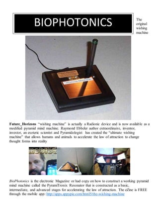
  • 1. The original wishing machine Future_Horizons “wishing machine” is actually a Radionic device and is now available as a modified pyramid mind machine. Raymond Ebbeler author extraordinaire, inventor, investor, an esoteric scientist and Pyramidologist has created the “ultimate wishing machine” that allows humans and animals to accelerate the law of attraction to change thought forms into reality BioPhotonics is the electronic Magazine or had copy on how to construct a working pyramid mind machine called the PyramiTronix Resonator that is constructed as a basic, intermediate, and advanced stages for accelerating the law of attraction. The eZine is FREE through the mobile app: http://apps.appypie.com/html5/the-wishing-machine BIOPHOTONICS
  • 2. Preface: Author’s Findings Supported by Wikipedia and Peer-Reviewed Research The purpose for constructing a prototype model of the Great Pyramid at Giza Egypt is to identify the shape as a resonant cavity. According to Wikipedia a resonator is cavity and is defined as: A resonator is a device or system that exhibits resonance or resonant behavior, that is, it naturally oscillates at some frequencies, called its resonant frequencies, with greater amplitude than at others. The oscillations in a resonator can be either electromagnetic or mechanical (including acoustic). Resonators are used to either generate waves of specific frequencies or to select specific frequencies from a signal. Musical instruments use acoustic resonators that produce sound waves of specific tones. A Pyramid As A Cavity Resonator A cavity resonator, usually used in reference to electromagnetic resonators, is one in which waves exist in a hollow space inside the device. Acoustic cavity resonators, in which sound is produced by air vibrating in a cavity with one opening, are known as Helmholtz resonators. A physical system can have as many resonant frequencies as it has degrees of freedom; each degree of freedom can vibrate as a harmonic oscillator. Systems with one degree of freedom, such as a mass on a spring, pendulums, balance wheels, and LC tuned circuits have one resonant frequency. Systems with two degrees of freedom, such as coupled pendulums and resonant transformers can have two resonant frequencies. A crystal lattice composed of N atoms bound together can have N resonant frequencies. As the number of coupled harmonic oscillators grows, the time it takes to transfer energy from one to the next becomes significant. The vibrations in them begin to travel through the coupled harmonic oscillators in waves, from one oscillator to the next. The term resonator is most often used for a homogeneous object in which vibrations travel as waves, at an approximately constant velocity, bouncing back and forth between the sides of the resonator. The material of the resonator, through which the waves flow, can be viewed as being made of millions of coupled moving parts (such as atoms). Therefore they can have millions of resonant frequencies, although only a few may be used in practical resonators. The oppositely moving waves interfere with each other to create a pattern of standing waves in the resonator. If the distance between the sides is , the length of a round trip is . To cause resonance, the phase of a sinusoidal wave after a round trip must be equal to the initial phase so the waves self-reinforce. The condition for resonance in a resonator is that the round trip distance, , is equal to an integral number of wavelengths of the wave: If the velocity of a wave is , the frequency is so the resonant frequencies are: So the resonant frequencies of resonators, called normal modes, are equally spaced multiples (harmonics) of a lowest frequency called the fundamental frequency. The above analysis assumes the medium inside the resonator is homogeneous, so the waves travel at a constant speed, and that the shape of the resonator is rectilinear. If the resonator is inhomogeneous or has a nonrectilinear shape, like a circular drumhead or a cylindrical microwave cavity, the resonant frequencies may not occur at equally spaced multiples of the fundamental frequency. They are then called overtones instead of harmonics. There may be several such series of resonant frequencies in a single resonator, corresponding to different modes of vibration.
  • 3. Because of the universe and cosmos as a space- time continuum -- a region for aether to be abundant for all to harness is the Great Pyramid which also incorporates in its sides and angles the means for creating a highly sophisticated map projection of the northern geo-hemisphere. Further along with the other two Giza pyramids replicates the exact positions of the three stars in the Constellation Orion where is an example of The Golden Spiral, whereby the three pyramids and the Sphinx are interlocked and thus situated by design. The PyramiTroniX Resonator similarly introduces the shape for the invention which accelerates the Law of Attraction as a scaled down version for the “pyramid housing assembly.” The purpose for this housing is to capture the electron (photon) discharge abundant in the aether which couples with the bio-photons of an individual's brain and body. The present invention provides a method and apparatus that addresses "putative" energy fields or bio fields which have denied measurement based on the concept that humans are infused with a subtle energy having 70 different names such as chi, ki, prana, life force, etc. However, in theoretical physics, scalar field theory can refer to a classical or quantum theory of scalar fields. A field which is invariant under any Lorentz transformation is called a "scalar", in contrast to a vector or tensor field. The quanta of the quantized scalar field are spin-zero particles, and as such are bosons. The only fundamental scalar field that has been observed in nature is the Higgs field. However, scalar fields appear in the effective field theory descriptions of many physical phenomena. An example is the pion, which is actually a "pseudoscalar", which means it is not invariant under parity transformations which invert the spatial directions, distinguishing it from a true scalar, which is parity-invariant. Because of the relative simplicity of the mathematics involved, scalar fields are often the first field introduced to a student of classical or quantum field theory. In particle physics, a pion (or a pi meson, denoted with the Greek letter pi: π) is any of three subatomic particles: π0, π+, and π−. Each pion consists of a quark and an antiquark and is therefore a meson. Pions are the lightest mesons (and, more generally, the lightest hadrons), because they are composed of the lightest quarks (the u and d quarks). They are unstable, with the charged pions π+ and π− decaying with a mean lifetime of 26 nanoseconds (2.6×10⁻⁸ seconds), and the neutral
  • 4. pion π0 decaying with a much shorter lifetime of 8.4×10⁻¹⁷ seconds. Charged pions most often decay into muons and muon neutrinos, and neutral pions into gamma rays. Nonetheless, since biofields have not been measured by conventional instruments and that neither the external field nor their therapeutic effects have been robustly scientifically demonstrated as a biophysical process, the objective is to design a method and apparatus that focuses on the interactions of the brain (consciousness) and body (cardiac) to amplify emotional, mental, social, and spiritual parameters of human growth and self- development. Non-invasive measurement can determine various changes in biological system s which includes the chemical analysis of blood, urine, and other processes relative to bio-photonic discharge usually considered the waste by- product of metabolism. Previously, infrared photon energy was used since the kinetic energy of thermal movement of molecules is E = 0.132 eV (electron volts) at 9,350 nm (nanometers). In contrast is the 1.67 - 3.41 eV (electron volts) of visible photons necessary for cells to regenerate regarding bio-photon emissions (BPE) as natural processes. Bearden (1995) determined 1kg of mass was equivalent to 17.053 X 10 ^ 50 and served as an "action switch" as a small as a quantum as defined by Planck's constant divided by four. He de-differentiated an infected cell (DND) and it was the de-differentiation process that indicated the DNA as a "time-reversal" potential at its previous state of health and wellness. However a problem observed is between energy and the energy density flow relative to Einstein's E=MC ^2. He related that electromagnetic energy trapped in space is equal to c ^2 (time squared) since energy can be transformed from one state to another state. However, a reference to Whitaker's (1903) seminal paper "On the partial differentiation equation of mathematical physics" indicates that scalar potentials can be decompositioned into a harmonic series of bio- directional electromagnetic wave pairs. Of significance is that each wave pair consists of a wave and its phase conjugate (anti-wave) observed as a "virtual" or phantom effect. By the "distortion correction theorem" of non- linear optics (not yet in existence til 1970) was each wave pair (wave, anti-wave) as a superposition for space (wave) and time (anti-wave). Therefore each wave pair appears as a standing wave where each point as (E ) energy of the wave and (-E) N-energy of the anti-wave simultaneously superimpose with each other. In superposition (E, -E); individual vectors do not cancel or cease to exist since the wave pair passes through space as observed by the observer. For this to occur, an observation time is needed to detect the "observation effect" as E and -E. However, it is the E(T) and -E(T), the "observation time differentiation" which removes time so that the observer will observe a zero an d a non-E field comprised of E + (-E) = 0. Thus the scalar field densities can b e summed at any point and a gravitational standing wave is superposed as the true phase conjugate replicated (time-reversal of wave pairs) and the electromagnetic field is converted to gravity. Whitaker indicated that the wave pair include s photons/anti-photons as pairs -- a spin 2 entities called gravitons, not individual photon in the 4th dimension (time). Whereas, E(T) and -E(T) did not cancel in the 3rd dimension (space). Mind, Body, & Spirit Development The practical scalability of the PyramiTroniX Resonator as a full-scale model can now evolve as a trihierarchical stage of development regarding mind, body and spiritual. Contemporary neuroscience research addresses the existence of algorithms for all sensory transduction necessary as brain-specific coding referred to as "intrinsic data fields" (IDF). Direct stimulation of these codes are within the human temporal or limbic cortices with application of electromagnetic patterns which usually require high energy levels. However, a scaled down process is coupling a narrow band whose frequencies range from 1 - 15 cycles per second HZ (Hertz).
  • 5. Although the resultant vector summation of the E field is a zero vector, the scalar field densities can be summed at any point thus “non-localization.” Of particular interest is Dirac (1929) who postulated a "quantum theory" for the electron and predicted anti particles and electrons or positrons through the process of " positron annihilation" where the pairing of electrons produce a photon and the new area of research became known as "Quantum Electrodynamics" (QED). Thus non-localization was not an instantaneous connection across space, but rather time which coupled separate systems where no physical (phantom) activity or interaction occurs at the speed of light...but thought. Since non-localization was based on deBroglie-Boem's theory which occurs when an electric current was passed through hydrogen gas, a radiated light, when dispersed through a prism produced a line spectrum and supported Heisenberg's Uncertainty Principle based on energy and time as a functional relationship. It further purports that if energy was sufficient to penetrate a barrier, the electron could "tunnel" through that barrier by sharing "surplus" (free) energy based on superposition when the electron is a wave function. Since neurons can be excited by externally applied time-varying electromagnetic fields, the pulse current I(T), the point source to where a cell could be positioned above the forehead (pineal gland) an/or adjacent to the head (temporal lobe s) activate the E-field in tissue based on Faraday's law" V x E= alphaB / alpha T where B is the magnetic field produced by the coil based on Biot-Savart Law B (r1, t) = mu0 / 4 pi => d/r ^1 X (r-r ^1) / 1r - t (1/3) These laws are amenable to scientific method as a non-invasive imaging process where the brain as a charge point can be measured as a field outside the head indicative of metabolic and hemo (blood) dynamics. The conventional neuroscience provides evidence-based research for multiple techniques regarding imaging. Raymond W. Ebbeler, Ph.D. (Candidate; on Sabbatical) Health Psychology, Walden University The Wishing Machine This amazing machine is actually just a type of “Psionic” amplifier that works using a direct link to your own mind. It essentially amplifies your intent or wish and can help to materialize it into your reality. The machine is simply a tool and the real power actually comes from the person using it so the more focused your mind and willpower is the better your results will be.
  • 6. This technology has been around for many years and was successfully tested many times even in laboratory conditions. Many people thought it was complete nonsense but now conventional science is finally catching up. Some researchers now believe that it is a Quantum Mechanics effect that allows the machine to work. A thought experiment invented by Albert Einstein, Boris Podolsky, and Nathan Rosen back in the late 1930's has now begun to scientifically substantiate much of the psychic and Psionic phenomenon. It is a sort of bizarre loophole in quantum physics known as the EPR (Einstein-Podolsky- Rosen) effect that seems to tell us that our world is put together in such a way that an event going on in a distant galaxy or in the mind of a friend across town is also going on in some analogous way in our own mind simultaneously. The experiment is a bit complex and rather difficult to explain but here it is: The experiment involves what physicists call a two particle system of zero spin. This means that you have two particles, such as two electrons, one spinning one way and the other spinning in exactly the opposite way so that the spin of each of the electrons cancels the other out. One spins right while the other spins left or one spins up while the other spins down. In the experiment the two particles are separated electrically so that their spins should not have an effect on one another. Now comes the strange part. Physicists were able to affect the spin of one of the electrons randomly using a magnetic field and found that the other electron seemed to know instantly that this occurred and it reverses its own spin to maintain equilibrium of spin cancellation. This experiment tends to confirm that there is a universal connectedness with all things within our world. And that information about any part of the whole is instantly available to any single part! This strange connectedness proven by the EPR effect has a mathematical proof known as Bell's theorem, which was published in 1964 by J .S. Bell, a physicist at the European organization for nuclear research (CERN) in Switzerland. Bells theorem implies that at a fundamental level the "separate parts" of the universe are connected in an intimate and immediate way. Another amazing part of this is the fact that this type of informational transfer if you will takes place instantaneously everywhere in the universe. This has some incredible and far reaching implications in the way our reality actually works. The experiment gives confirmation to the belief that all matter in the known universe exhibits a universal connectedness and that information is available and accessible to anything or anyone who knows the secret of accessing it. This is like a universal collective unconscious. This also means that the subconscious minds of all people are also collectively linked on some level together and to the rest of the universe. The same apparently goes for all physical matter. FutureHorizons Dr. Raymond Brown and the Underwater Pyramid In 1970, Dr. Ray Brown, a naturopathic practitioner from Mesa, Arizona, was scuba diving with friends near the Bari islands, Bahamas, in an area 20 miles from the edge of a submarine drop-off called the Tongue of the Ocean. During the dive, Brown became separated from his companions, and in trying to rejoin them, suddenly saw a strange pyramid shape looming up against the aquamarine light. The pyramid was situated 22 fathoms down, stood 120 feet high, with only 90 feet projecting out of the sea floor shifting sands. Brown was at first struck by how smooth and mirror- like the stone surface of the structure was, with the joints between the individual blocks almost indiscernible. Swimming about the capstone, which the Arizona diver thought looked like lapis lazuli, he discovered an entranceway and decided to explore further. Passing along a narrow hallway, Brown finally came to a small rectangular room with a pyramid-shaped ceiling. What was amazing was that the room contained no algae or coral growing on the inner walls. They were completely spotless. In addition, though Brown had brought no flashlight, he could nevertheless see everything in the room perfectly. It was very bright and well lit, but no direct light source was visible. Brown's attention was drawn to a brassy metallic rod 3 inches in diameter hanging down from the apex of the center, and at its end was attached a many-faceted red gem, which came to a point. Directly below the rod and gem, sitting in the middle of the room was a stand of carved stone topped by a stone plate with scrolled ends.
  • 7. On the plate rested a pair of carved metal bronze-colored hands, life-sized, which appeared blackened and burnt, as if having been subjected to tremendous heat. Nestled in the hands, and situated 4 feet directly below the ceiling rod gem point, was a crystal sphere 3-1/2 inches in diameter. Brown first attempted to pry loose the ceiling rod and red gemstone, but neither would budge. Turning back to the crystal sphere he found it easily separated from the bronze hand holders, and left the pyramid with it. As he departed, Brown felt a presence, and heard a voice from somewhere telling him never to return. Fearing that his unusual prize might be confiscated as salvage-treasure by the U.S. government, Dr. Brown did not disclose the existence of the strange crystal or his experiences until 1975, when he exhibited the crystal for the first time. He displayed the crystal only a half dozen times, but each time witnesses have seen or have been sensitive to strange phenomena directly associated with it. Deep inside the crystal form one gazes upon three pyramid images, one in front of the other, in decreasing sizes. Some, entering into a meditative or alpha brainwave state of consciousness, are able to clearly see a fourth pyramid, in the foreground of the other three. The significance of the image may have been hinted at by psychic Elizabeth Bacon of New York. In a trance reading on the mysterious sphere, she received the message that the object had once belonged to Thoth, the Egyptian god who ages ago buried a secret vault of knowledge at Giza, near the three great Pyramids there. Do the positions of the three pyramid images in the crystal hold a key to finding a fourth, as yet unfound subterranean pyramid, that is the fabled Hall of Records? From the side, the internal images dissolve into thousands of tiny fracture lines, and Brown feels these may be electrical in nature, like some form of microscopic circuitry. From still another angle, and under special conditions, many witnesses have been able to see a large single human eye staring out serenely at them. Photographs of this eye have also been taken. Like the mysterious crystal skull of Central America, Dr. Brown's crystal sphere is the source of a variety of paranormal events. People have felt breezes of ionic winds blowing close to it; cold and warm layers surround it at various distances; other witnesses have been phantom lights, heard voices, or felt strange tingling sensations around it. A compass needle placed next to the sphere will spin counterclockwise, then begin turning in the opposite direction when moved only two inches away. Metals are temporarily magnetized in close contact with it. There are even recorded instances where one person has been temporarily healed of an ailment by touching the crystal sphere, but then the next person to come into its range took on the symptoms of the ailment of the other person, as if the crystal could draw out and then activate human disorders at will. Just what the purpose of the crystal sphere was, and what role it once played in the enigmatic instrument Brown found inside the sunken Bahaman pyramid, remains a mystery, though of course there are some interesting possibilities. One idea proposed is that the sunken pyramid once attracted, accumulated and generated cosmic forces. The suspended rod may have conducted forces accumulated in the capstone; the faceted red gem at its end concentrated and projected the energy to the crystal sphere below it; and the burnt and blackened hands, showing the evidence of an energy transfer, probably amplified the release of energies; while the crystal sphere acted as the tuner and broadcaster of the energies. All that we know for certain is that the crystal sphere Dr. Brown retrieved from this system is by itself testimony to a most sophisticated technology, for as experts at the Smithsonian Institute in Washington noted, the technology for cutting quartz stone to the perfection exhibited in the crystal sphere was not accomplished by our civilization until after 1900. Is It Alien Technology? Another Variant Is The Telepathic Pyramid
  • 8. The painting also shows the exact shape and relative size of the pyramid, as well as the manner it was held by the being. The colour scheme of the pyramid’s surface, as well as shadows and illustration of walls’ transparency, is conveying the impression that Daniela got when looking at the working pyramid. Fig. C2. A photograph of the pyramid Shown is a prototype of this device built in Poland, but not made operational. More details about the purpose, operation, and theory behind this device is provided in treatise [7], in chapter G of monographs [3] & [3/2], as well as in chapter N of monographs [1/2] & [1/3]. Research on the prototype completed by Daniela indicated that after an alternating current of high frequency is supplied to the device from an external source (e.g. from a radio) the pyramid produces some kind of telepathic signal. However, her prototype still hides some construction errors which make it impossible to operate according to the original specification of the giver. To eliminate these errors, further theoretical research and physical development needs to be carried out.  (Top) The side view of the whole pyramid. The device is held by myself (Dr Jan Pajak) in a manner similar as the little being with blue eyes held it in his hands. During such holding the biofield of the user infiltrates through the active space of the device. Because this bio-field carries the thoughts of the user, it modifies with these thoughts the state of the optical interference cavity. In turn the modifications of this optical interference cavity are imposed onto the electrical oscillations from the pyramid’s resonator, thus modulating these oscillations.
  • 9. After the modulation into magnetic vibrations these thoughts are emitted into space from which they can be intercepted by another similar device. After being intercepted these thoughts are demodulated and superimposed on the biofield of another user, thus appearing in his/her mind as another set of thoughts imposed on his/her own.  (Bottom) The inner components of the pyramid. The casing (hat) is visible from underneath after being put aside on the right. Fig. C3. The general shape, design, and main components of the pyramid This illustration is prepared as if all the elements were transparent, i.e. through subsequent components the elements, shapes, and connections placed behind them are visible. It represents a repetition of Figure N2 from monographs [1/3] and [1/2], and Figure 1 from treatise [7]. This device is shaped as a pyramid of around 27.5 [cm] high. Its wiring and main components are hermetically enclosed inside a pyramidal casing made of perspex or glass. The casing hosts: a copper frame (F) shaped like a pyramid and aligning each corner of the casing, a conical coil © also made of a copper wire, four aluminium disks (D1), (D2), (D3), (D4) attached to the side walls of the pyramidal casing - one of them (D1) should have a
  • 10. small hole in the centre, quartz crystal (Q) placed at ¼ of the height, phial (T) placed in the centre of the base, two inductors (I1) and (I2), and four cascades of mirrors (M1), (M2), (M3), (M4) placed in four corners of the base. All these components should not touch each other, although they should be electrically connected together according to the original instruction. Their electrical properties should fulfil the condition of “harmonic” proportions. The phial (T) should be half filled with ordinary kitchen salt, half with mercury. It is recommended that it should work under a vacuum. Both inductors (I1) and (I2) are made of small bar magnets with copper wiring tightly winded around them. Each cascade of mirrors (M) is made of three small mirrors of descending heights. The copper frame (F) is simply eight pieces of copper wire joined together so that they form the shape of a pyramid. It is recommended that the whole pyramid should be under a vacuum. Fig. D1. The electrical diagram which illustrates the basic circuits and connections existing in the pyramid It is reproduced from Figure N3 of monograph [1/3]. The continuous lines indicate the connections that were described to Daniela in the original disclosure. The broken lines indicate electrical connections which were not included in the original disclosure, but the existence of which is explained by theories described in chapter D of this treatise (chapter D explains the phenomena, principles, and basic circuits involved in the pyramid’s operation). The below diagram illustrates my knowledge about the operation of this device at the time of writing this treatise (the further theoretical research which I continually carry out, combined with experiments which hopefully will be inspired by this treatise and may be completed by readers, in future may introduce some improvements to this diagram). Names of subsequent components of this pyramid are reflecting the use of this device as a telepathyser. The corresponding names of the same components for the operation of the pyramid as a telekinetic battery are
  • 11. explained in subsection D2.4. The pyramid is composed of the following main circuits and individual components: (1) receiving antenna for telepathic waves. It is composed of the quartz crystal (Q) placed in the focal point of the telepathic resonance cavity that is formed from four aluminium disks (D1, D2, ... D4). (2) The modulating and demodulating circuit (resonator - R). It is composed of such components as inductors (I1) and (I2), a glowing tube (T), and a vacuum capacitor. The capacitor is formed out of two types of “plates” (which differ in shapes), separated from each other with a layer of vacuum (or air). The first of these “plates” is formed from four aluminium disks (D1, D2, ... D4) connected together. The second “plate” of the capacitor is formed from a conical coil © and a frame (F) connected to it. In order to increase the communicativeness of this diagram, the resonator circuit is marked with a dotted line ®. (3) The optical interference chamber/cavity which functions as an “inouter” for thoughts. It is composed of: a glowing tube (T) and not shown here four cascades of mirrors (M) which cooperate with this tube. (4) Emitting antenna which forms the telepathic waves and sends them throughout counter-world. It has a shape of a conical coil ©. Fig. D2. A revealing device. It represents a simplified, self-defense version of telepathic telescopes Such devices, if completed, would enable us to see our cosmic parasites which so-far successfully were hiding from our sight by entering a state of telekinetic flickering. More thoroughly the design of this device is described in treatise [7B]. A state of telekinetic flickering is accomplished by switching on a sequence of fast pulses of the telekinetic field. Each such a pulse is turning the object that is wrapped into this field into a transparent energy pattern or cloud. But between these pulses the object remains material and visible. Therefore, if such a flickering is fast enough, the object becomes unnoticeable for our eyes, similarly as in our motion pictures the flickering of individual frames becomes invisible for us. But each pulse of the telekinetic field can be intercepted by the device showed here, and revealed as a glowing shape. Therefore the revealing device illustrated here allows us to see normally invisible UFOnauts and their vehicles. They appear as glowing figures at the device’s electromagnetic screen (s). As this is the case with optical telescopes, also the revealing devices are composed of a main tube (t), on which all other components are to be assembled. At the frontal part of this tube a focusing magnetic lens (f) is assembled. At the rear part of the same tube the viewing magnetic lens (v) is assembled. In a simplified, self- defence version of the telepathic telescopes called here “revealing devices”, such lenses (f) and (v) are simply permanent magnets (or permanent electromagnets which use DC). In centre of the tube an electromagnetic screen (s) is formed - see the dotted plane extending across the tube (t). This screen is composed of a collision surface and the athwart electrostatic field. The collision surface (s) is formed by the two magnetic fields bumping into each other with their magnetic poles (O) which represent an “outlet” for flow of counter-matter (for the notation of magnetic polarity used by present physicists: O=N). The athwart electrostatic field which is spreading from two thin electrodes (e) extending along the peripherals of the collision surface and placed at the opposite side of the tube (t). The whole interior of the tube must be filled up with an extraction glow generating substance (g).
  • 12. Back to Contents Appendixes Appendix Z1 List of illustrations of the treatise [7/2] “Pyramid of thoughts” (ISBN 0-9583727-1-3) Because copies of this treatise [7/2] are to be available via Internet, where the inclusion of illustrations may pose a technical problem, in this listing of illustrations additional information is provided which indicates which of the publications listed i chapter G also contains a given Figure (most of publications listed in chapter G was supplied to the National Library of Poland, to all libraries of province capitols in Poland, and also to the main libraries of almost all higher education institutions in Poland, not mentioning similar libraries in New Zealand and in several other countries outside Poland). For example the symbol [1/3]-F1 means that a give illustration is also included into the monograph [1/3] as Figure F1. The use of symbol ~ indicates either an older version of the same illustration, or illustration very similar, while the use of symbol ¨ indicates a colour print of a given photograph. Note that in the following pairs of monographs very similar illustrations were used: [1/2] & [1/3], [3] & [3/2], [5] & [5/2], [5/3] & [5/4], [6] & [6/2]. Also the Polish and other language versions of the same publications have identical illustrations, e.g.: [5/2] & [5/2E], or [7], [7E] & [7I]. Treatise [7/2] includes 29 illustrations, which in the printed versions of this treatise are arranged into 12 Figures, a title page, and 2 “about the authors” pages. In Internet each of these illustrations is available as a separate item. Symbols assigned to individual illustrations/items reflect their location on a given Figure. Thus illustrations the symbol of which includes letter “H” are placed in the higher row of a Figure, while illustrations with letter “L” are placed in the lower row of a Figure. Within a given row, symbols “l, m, r” mean the location on left, in the middle, or on right. In turn symbols “a, b, c”, or “1, 2, 3, 4”, indicate a writing-type order within a given Figure.  Fig. A1. The smallest Magnocraft - type K3. [4B]-B1, [5/2]-19, [5/4]-G2, [1/3]~F1, [6/2]-10, o (A1a) General design and components of K3 type Magnocraft. [1/3]-F1, [1E]-B1, [1I]B1, [3/2]~H1, o (A1b) Side view of the smallest magnecraft type K3. [1/3]-F1, [1E]-G4, [1I]-G4, [5/4]-G2, o (A1c) Twin-chamber capsule composed of two oscillatory chambers. [1/3]-C5, [1E]-F4, [1I]-F4, [2]C4, [3/2]-F5,  Fig. A2. Flying arrangements formed by magnocraft. [1E]-G6, [1I]-G6, [2]-D3, [3/2]-H3, [5/3]-F5, [6/2]-12, [4B]-B2,  Fig. A3. Scorch marks left on the ground by landed UFOs. o (A3H) Connection between a vehicle’s height and a shape of landing site. [1/3]-F33, [1I]~G38, [5/2]-23, [5/3]-F3, o (A3L) Photographs of landing sites scorched by single UFOs. [1/3]-P1, [5/2]~33, [5/3]~G9, o (A3Ll) Two concentric rings. [1/3]-P1, [1E]-M7/H, [1I]-K1, [5/2]-33ª, [5/3]-G9, [5/4]-H9a, o (A3Lm) A ring with central scorching. [1/3]-P1, [1E]-M2/H, [5/2]-33b, [5/3]-G9, [5/4]-H9b, o (A3Lr) A ring with a flange. [1/3]-P1, [5/2]-33c, [5/3]-G9, [5/4]H9c,  Fig. A4. The Tapanui crater where around 7 UFO vehicles exploded in 1178 AD. [1/3]-P4, o (A4H) A photograph of the Tapanui crater’s eastern slope. [1/3]-P4, [1E]-M19d, [1I]¨K4/L, [5/2]2, [5/3]-A2, [5/4]-A2, o (A4L) Comparison of similarities between Tapanui and Tunguska. [1/3]-P5, [1E]-M30, [5/2]-8, [5/3]-C6, [5/4]-C6  Fig. A5. Examples of underground tunnels evaporated in rocks by UFOs. [1/3]-P6, [5/2]~32, [6/2]~21, (#1-#3) Photos of tunnels evaporated in rocks by UFOs. [1/3]-P6, [4B]-B4, o (A5_1) Cocklebiddy Cave, Australia. [1E]-M18, [1I]¨K3/1, [5/2]-32/2, [5/3]-G8, [6/2]-21/2, [4B]- B4b, o (A5_2) Deer Cave, Borneo, Malaysia. [1/3]-P6, [4B]-B4/L, o (A5_3) Tunnel Morona-Santiago, Ecuador. [1E]-M17, [1I]¨K3/2ª, [5/2]-32/1, [5/3]-G8, [6/2]-21/1, [4B]-B4a,
  • 13. o (A5_4) Principles of formation of underground tunnels by UFOs. [1/3]-F31, [4B]-B3, [1E]~G36, [1I]~G36,  Fig. B1. The 550 million year-old imprint of human foot. [1/3]-O32,  Fig. B2. An old church painting on the Crucifixion supervised by UFOs. see description under Fig. B2,  Fig. C1. The little white being with blue eyes holding the pyramid. this illustration is unique for [7/2],  Fig. C2. A photograph of the pyramid described here. [1/3]-N1, [3/2]-G1, [5/3]-F8, [7]~2, o (C2H) Dr Jan Pajak holding the pyramid. [1/3]-N1, [3/2]-G1, [5/3]-F8, [7]~2, o (C2L) A photograph of the pyramid’s interior. [1/3]-N1, [3/2]-G1, [5/3]-F8, [7]~2,  Fig. C3. The internal design of the pyramid described here. [1/3]-N2, [3/2]-G2, [7]-1,  Fig. D1. The electrical circuitry (connections) of the pyramid described here. [1/3]-N3, [3/2]-G3, Fig. D2. A revealing device. [7B]-1/H. Independently from Figures listed above, treatise [7/2] uses also one drawing on the front page which represents a repetition of illustration from Fig. C1, and also includes passport-type photographs of both authors included into descriptions from chapter H “About Authors”. Back to Contents Integrating the Pyramid Cavity and the Coupling Coefficient of Resonators: The Wishing Machine Schematic Wikipedia defines a coupling coefficient of resonators as having a dimensionless value that characterizes interaction of two resonators: in this case…the Pyramid Cavity and the Wishing Machine Schematic as Coupling coefficients which are used in resonator filter theory. Since resonators may be both electromagnetic and acoustic the coupling coefficients are synchronized together with resonant frequencies within the alpha – theta range such that the external quality factors of resonators are better generalized parameters of filters. In order to adjust the frequency response of the filter it is sufficient to optimize only these generalized parameters that are specific to the Pi (3.14) and Phi (1.618) ratios found in nature. Evolution of the term Resonator Coupling coefficient considered as a positive constant Earlier well-known definitions of the coupling coefficient of resonators are given in monograph by G. Matthaei et al.[2] Note that these definitions are approximate because they were formulated in the assumption that the coupling between resonators is sufficiently small. However, the coupling coefficient for the case of two equal resonators such as the scaled down model of the Great Pyramid and a Tesla Coil is a positive constant as a longitudinal or standing wave that emits a scalar energy
  • 14. The Pyramid cavity is a nodal representation for information transfer which characterizes interaction of “contextual” resonators as a resonant frequency range: Alpha – Theta The PyramiTroniX Resonator will be a conduit for focusing thought to change one’s realty using the mind- body-spirit triad which is the ultimate spiritual experience of transcendence.
  • 15.
  • 16. Bandpass filters with cross couplings
  • 17. The Pyramidal Cell In the Human Brain and Body Exoteric versus Esoteric Science As an exoteric scientist I was interested in using Psychoneuroimmunology to emphasize biophotonic emission, while I also was an esoteric scientist / pyramidologist and adhered to the discipline of Radionics as an innovative approach to integrating the mind-body problem in health psychology. I found that Psychoneuroimmunology actually addressed the overlap in the health and wellness industry as an alternative medicine that the American Medical Association (AMA) regards as a pseudoscience that I found it necessary to start a non-profit: Black Box Energies & Research. Unfortunately, the web site was removed and I had to go underground to do research on Radionics. Having traveled to the United Kingdom ten years previously in 1988 as an exchange student in World Art 101; I attended a conference held by the Radionics society in Oxford, England.
  • 18. Basic Evolution of Radionics: The Human-Machine Interface & the Wishing Machine Circuit The Heironymus Machine SymbolicsActual https://youtu.be/uYL3tQborDw Radionics: United States & United Kingdom From Wikipedia, the free encyclopedia Jump to: navigation, search Contemporary Radionic instruments Radionics is an alternative medicine that claims disease can be diagnosed and treated with a kind of energy similar to radio waves.[1] The concept behind radionics originated in the early 1900s with Albert Abrams (1864– 1924), who became a millionaire by leasing radionic machines which he designed himself.[1] Radionics contradicts some principles of physics and biology and so is commonly considered pseudoscience.[2] The United States Food and Drug Administration does not recognize any legitimate medical uses for such devices.[1][2][3] The Wheatsone Bridge as a Substitute for the Radionic Circuit A Wheatstone bridge is an electrical circuit used to measure an unknown electrical resistance by balancing two legs of a bridge circuit, one leg of which includes the unknown component. Its operation is similar to the original potentiometer. It was invented by Samuel Hunter Christie in 1833 and improved and popularized by Sir
  • 19. Charles Wheatstone in 1843. One of the Wheatstone bridge’s initial uses was for the purpose of soils analysis and comparison.[1] Operation In the figure, is the unknown resistance to be measured; , and are resistors of known resistance and the resistance of is adjustable. If the ratio of the two resistances in the known leg is equal to the ratio of the two in the unknown leg , then the voltage between the two midpoints (B and D) will be zero and no current will flow through the galvanometer . If the bridge is unbalanced, the direction of the current indicates whether is too high or too low. is varied until there is no current through the galvanometer, which then reads zero. Detecting zero current with a galvanometer can be done to extremely high accuracy. Therefore, if , and are known to high precision, then can be measured to high precision. Very small changes in disrupt the balance and are readily detected. At the point of balance, the ratio of Alternatively, if , , and are known, but is not adjustable, the voltage difference across or current flow through the meter can be used to calculate the value of , using Kirchhoff’s circuit laws (also known as Kirchhoff’s rules). This setup is frequently used in strain gauge and resistance thermometer measurements, as it is usually faster to read a voltage level off a meter than to adjust a resistance to zero the voltage. The 555 Timer Integrated Chip
  • 20. The 555 timer IC is an integrated circuit (chip) used in a variety of timer, pulse generation, and oscillator applications. The 555 can be used to provide time delays, as an oscillator, and as a flip-flop element. Derivatives provide up to four timing circuits in one package. Introduced in 1971 by American company Signetics, the 555 is still in widespread use due to its ease of use, low price, and stability. It is now made by many companies in the original bipolar and also in low-power CMOS types. As of 2003, it was estimated that 1 billion units are manufactured every year.[1]A Design Internal schematic Internal schematic (CMOS version) The IC was designed in 1971 by Hans Camenzind under contract to Signetics, which was later acquired by Dutch company Philips Semiconductors (now NXP). Depending on the manufacturer, the standard 555 package includes 25 transistors, 2 diodes and 15 resistors on a silicon chip installed in an 8-pin mini dual-in-line package (DIP-8).[2] Variants available include the 556 (a 14- pin DIP combining two 555s on one chip), and the two 558 & 559s (both a 16-pin DIP combining four slightly modified 555s with DIS & THR connected internally, and TR is falling edge sensitive instead of level sensitive). The NE555 parts were commercial temperature range, 0 °C to +70 °C, and the SE555 part number designated the military temperature range, −55 °C to +125 °C. These were available in both high-reliability metal can (T package) and inexpensive epoxy plastic (V package) packages. Thus the full part numbers were NE555V, NE555T, SE555V, and SE555T. It has been hypothesized that the 555 got its name from the three 5 kΩ resistors used within,[3] but Hans Camenzind has stated that the number was arbitrary.[1] Low-power versions of the 555 are also available, such as the 7555 and CMOS TLC555.[4] The 7555 is designed to cause less supply noise than the classic 555 and the manufacturer claims that it usually does not require a "control" capacitor and in many cases does not require a decoupling capacitor on the power supply. Those parts should generally be included, however, because noise produced by the timer or variation in power supply voltage might interfere with other parts of a circuit or influence its threshold voltages. Pins
  • 21. Pinout diagram The connection of the pins for a DIP package is as follows: Pin Name Purpose 1 GND Ground reference voltage, low level (0 V) 2 TRIG The OUT pin goes high and a timing interval starts when this input falls below 1/2 of CTRL voltage (which is typically 1/3 VCC, CTRL being 2/3 VCC by default if CTRL is left open). 3 OUT This output is driven to approximately 1.7 V below +VCC, or to GND. 4 RESET A timing interval may be reset by driving this input to GND, but the timing does not begin again until RESET rises above approximately 0.7 volts. Overrides TRIG which overrides THR. 5 CTRL Provides "control" access to the internal voltage divider (by default, 2/3 VCC). 6 THR The timing (OUT high) interval ends when the voltage at THR ("threshold") is greater than that at CTRL (2/3 VCC if CTRL is open). 7 DIS Open collector output which may discharge a capacitor between intervals. In phase with output. 8 VCC Positive supply voltage, which is usually between 3 and 15 V depending on the variation. Pin 5 is also sometimes called the CONTROL VOLTAGE pin. By applying a voltage to the CONTROL VOLTAGE input one can alter the timing characteristics of the device. In most applications, the CONTROL VOLTAGE input is not used. It is usual to connect a 10 nF capacitor between pin 5 and 0 V to prevent interference. The CONTROL VOLTAGE input can be used to build an astable multivibrator with a frequency modulated output. Modes The IC 555 has three operating modes:  Monostable mode: In this mode, the 555 functions as a "one-shot" pulse generator. Applications include timers, missing pulse detection, bouncefree switches, touch switches, frequency divider, capacitance measurement, pulse-width modulation (PWM) and so on.  Astable (free-running) mode: The 555 can operate as an oscillator. Uses include LED and lamp flashers, pulse generation, logic clocks, tone generation, security alarms, pulse position modulation and so on. The 555 can be used as a simple ADC, converting an analog value to a pulse length. E.g. selecting a thermistor as timing resistor allows the use of the 555 in a temperature sensor: the period of the output pulse is determined by the temperature. The use of a microprocessor based circuit can then convert the pulse period to temperature, linearize it and even provide calibration means.  Bistable mode or Schmitt trigger: The 555 can operate as a flip-flop, if the DIS pin is not connected and no capacitor is used. Uses include bounce-free latched switches. Monostable
  • 22. See also: RC circuit Schematic of a 555 in monostable mode The output pulse ends when the voltage on the capacitor equals 2/3 of the supply voltage. The output pulse width can be lengthened or shortened to the need of the specific application by adjusting the values of R and C.[5] The output pulse width of time t, which is the time it takes to charge C to 2/3 of the supply voltage, is given by where t is in seconds, R is in ohms (resistance) and C is in farads (capacitance). While using the timer IC in monostable mode, the main disadvantage is that the time span between any two triggering pulses must be greater than the RC time constant.[6] Bistable
  • 23. Schematic of a 555 in bistable mode In bistable (also called Schmitt trigger) mode, the 555 timer acts as a basic flip-flop. The trigger and reset inputs (pins 2 and 4 respectively on a 555) are held high via pull-up resistors while the threshold input (pin 6) is simply floating. Thus configured, pulling the trigger momentarily to ground acts as a 'set' and transitions the output pin (pin 3) to Vcc (high state). Pulling the reset input to ground acts as a 'reset' and transitions the output pin to ground (low state). No timing capacitors are required in a bistable configuration. Pin 5 (control voltage) is connected to ground via a small-value capacitor (usually 0.01 to 0.1 uF); pin 7 (discharge) is left floating.[7] Astable Standard 555 astable circuit In astable mode, the 555 timer puts out a continuous stream of rectangular pulses having a specified frequency. Resistor R1 is connected between VCC and the discharge pin (pin 7) and another resistor (R2) is connected between the discharge pin (pin 7), and the trigger (pin 2) and threshold (pin 6) pins that share a common node. Hence the capacitor is charged through R1 and R2, and discharged only through R2, since pin 7 has low impedance to ground during output low intervals of the cycle, therefore discharging the capacitor. In the astable mode, the frequency of the pulse stream depends on the values of R1, R2 and C: [8] The high time from each pulse is given by:
  • 24. and the low time from each pulse is given by: where R1 and R2 are the values of the resistors in ohms and C is the value of the capacitor in farads. The power capability of R1 must be greater than . Particularly with bipolar 555s, low values of must be avoided so that the output stays saturated near zero volts during discharge, as assumed by the above equation. Otherwise the output low time will be greater than calculated above. The first cycle will take appreciably longer than the calculated time, as the capacitor must charge from 0V to 2/3 of VCC from power-up, but only from 1/3 of VCC to 2/3 of VCC on subsequent cycles. To have an output high time shorter than the low time (i.e., a duty cycle less than 50%) a small diode (that is fast enough for the application) can be placed in parallel with R2, with the cathode on the capacitor side. This bypasses R2 during the high part of the cycle so that the high interval depends only on R1 and C, with an adjustment based the voltage drop across the diode. The voltage drop across the diode slows charging on the capacitor so that the high time is a longer than the expected and often-cited ln(2)*R1C = 0.693 R1C. The low time will be the same as above, 0.693 R1C. With the bypass diode, the high time is where Vdiode is when the diode's "on" current is 1/2 of Vcc/R1 which can be determined from its datasheet or by testing. As an extreme example, when Vcc= 5 and Vdiode= 0.7, high time = 1.00 R1C which is 45% longer than the "expected" 0.693 R1C. At the other extreme, when Vcc= 15 and Vdiode= 0.3, the high time = 0.725 R1C which is closer to the expected 0.693 R1C. The equation reduces to the expected 0.693 R1C if Vdiode= 0. The operation of RESET in this mode is not well defined, some manufacturers' parts will hold the output state to what it was when RESET is taken low, others will send the output either high or low. Specifications These specifications apply to the NE555. Other 555 timers can have different specifications depending on the grade (military, medical, etc.). Supply voltage (VCC) 4.5 to 15 V Supply current (VCC = +5 V) 3 to 6 mA Supply current (VCC = +15 V) 10 to 15 mA Output current (maximum) 200 mA Maximum Power dissipation 600 mW Power consumption (minimum operating) 30 mW@5V, 225 mW@15V Operating temperature 0 to 70 °C
  • 25. Derivatives Many pin-compatible variants, including CMOS versions, have been built by various companies. Bigger packages also exist with two or four timers on the same chip. The 555 is also known under the following type numbers: Manufacturer Model Remark Custom Silicon Solutions[9] CSS555/CSS555C CMOS from 1.2 V, IDD < 5 µA CEMI ULY7855 ECG Philips ECG955M Exar XR-555 Fairchild Semiconductor NE555/KA555 GoldStar GSC555 CMOS Harris HA555 Hitachi HA17555 IK Semicon ILC555 CMOS from 2 V Intersil SE555/NE555 Intersil ICM7555 CMOS Lithic Systems LC555 Maxim ICM7555 CMOS from 2 V Motorola MC1455/MC1555 National Semiconductor LM1455/LM555/LM555C National Semiconductor LMC555 CMOS from 1.5 V NTE Sylvania NTE955M Raytheon RM555/RC555 RCA CA555/CA555C STMicroelectronics NE555N/ K3T647 Texas Instruments SN52555/SN72555 Texas Instruments TLC555 CMOS from 2 V USSR К1006ВИ1 X-REL Semiconductor XTR655 Operation from -60°C to 250+°C Zetex ZSCT1555 (discontinued) down to 0.9 V NXP Semiconductors ICM7555 CMOS HFO / East Germany B555 556 dual timer[edit]
  • 26. Die of a 556 dual timer manufactured by STMicroelectronics. The dual version is called 556. It features two complete 555s in a 14 pin DIL package. 558 quad timer[edit] Die of a 558 quad timer. The quad version is called 558 and has 16 pins. To fit four 555s into a 16 pin package the power, control voltage, and reset lines are shared by all four modules. Each module's discharge and threshold circuits are wired together internally. Example applications Joystick interface circuit using the 558 quad timer The Apple II microcomputer used a quad timer 558 in monostable (or "one-shot") mode to interface up to four "game paddles" or two joysticks to the host computer. It also used a single 555 for flashing the display cursor. A similar circuit was used in the IBM PC.[10] In the joystick interface circuit of the IBM PC, the capacitor (C) of the RC network (see Monostable Mode above) was generally a 10 nF capacitor. The resistor (R) of the RC network consisted of the potentiometer inside the joystick along with an external resistor of 2.2 kilohms.[11] The joystick potentiometer acted as a variable resistor. By moving the joystick, the resistance of the joystick increased from a small value up to about 100 kilohms. The joystick operated at 5 V.[12] Software running in the host computer started the process of determining the joystick position by writing to a special address (ISA bus I/O address 201h).[12][13] This would result in a trigger signal to the quad timer, which would cause the capacitor (C) of the RC network to begin charging and cause the quad timer to output a pulse. The width of the pulse was determined by how long it took the C to charge up to 2/3 of 5 V (or about 3.33 V), which was in turn determined by the joystick position.[12][14] The software then measured the pulse width to
  • 27. determine the joystick position. A wide pulse represented the full-right joystick position, for example, while a narrow pulse represented the full-left joystick position.[12] See also Further reading  555 Timer Applications Sourcebook Experiments; H. Berlin; BPB Publications; 218 pages; 2008; ISBN 978-8176567909.  Timer, Op Amp, and Optoelectronic Circuits and Projects; Forrest Mims III; Master Publishing; 128 pages; 2004; ISBN 978-0-945053-29-3.  Engineer's Mini-Notebook – 555 Timer IC Circuits; Forrest Mims III; Radio Shack; 33 pages; 1989; ASIN B000MN54A6.  IC Timer Cookbook; 2nd Ed; Walter G Jung; Sams Publishing; 384 pages; 1983; ISBN 978-0-672- 21932-0.  555 Timer Applications Sourcebook with Experiments; Howard M Berlin; Sams Publishing; 158 pages; 1979; ISBN 978-0-672-21538-4.  IC 555 Projects; E.A. Parr; Bernard Babani Publishing; 144 pages; 1978; ISBN 978-0-85934-047-2.  Analog Applications Manual; Signetics; 418 pages; 1979. Chapter 6 Timers is 22 pages. External links Wikimedia Commons has media related to 555 timer IC.  555 Timer Circuits – the Astable, Monostable and Bistable  Simple 555 timer circuits  Java simulation of 555 oscillator circuit  NE555 Frequency and duty cycle calculator for astable multivibrators  Using NE555 as a Temperature DSP  555 Timer Tutorial  Common Mistakes When Using a 555 Timer  555 and 556 Timer Circuits  555 using areas and examples circuits  Working with 555 Timer Circuits Engineers Garage  Analysis and synthesis of a 555 astable multivibrator circuit - online calculator  Online simulations of a 555 astable multivibrator circuit - online simulator IC Datasheets  NE555, Single Bipolar Timer, Texas Instruments  NE556, Dual Bipolar Timer, Texas Instruments  NE558, Quad Bipolar Timer, NXP  LMC555, Single CMOS Timer, Texas Instruments (operates down to 1.5 Volt at 50 uAmp)  ICM755x, Single / Dual CMOS Timer, Intersil (operates down to 2.0 Volt at 60 uAmp)  ZSCT1555, Single CMOS Timer, Diodes Inc (operates down to 0.9 Volt at 74 uAmp)  TS300x, Single CMOS Timers, Touchstone (operates down to 0.9 Volt at 1.0 uAmp)  XTR65x, HiRel HiTemp Timer, X-REL (operates from -60°C to 230°C)
  • 28. The Differential Threshold as Potentiometers The basic set up for a three-dial Radionic device using a crystal as a resonator circuit and a stick pad A potentiometer /pɵˌtɛnʃiˈɒmɨtər/, informally a pot, is a three-terminal resistor with a sliding or rotating contact that forms an adjustable voltage divider.[1] If only two terminals are used, one end and the wiper, it acts as a variable resistor or rheostat.
  • 29. The measuring instrument called a potentiometer is essentially a voltage divider used for measuring electric potential (voltage); the component is an implementation of the same principle, hence its name. Potentiometers are commonly used to control electrical devices such as volume controls on audio equipment. Potentiometers operated by a mechanism can be used as position transducers, for example, in a joystick. Potentiometers are rarely used to directly control significant power (more than a watt), since the power dissipated in the potentiometer would be comparable to the power in the controlled load. Albert Abrams
  • 30. Scientific Method Versus Pseudoscience According to radionics practitioners, a healthy person will have certain energy frequencies moving through their body that define health, while an unhealthy person will exhibit other, different energy frequencies that define disorders. Radionic devices purport to diagnose and heal by applying appropriate frequencies to balance the discordant frequencies of sickness. Radionics uses "frequency" not in its standard meaning but to describe an imputed energy type, which does not correspond to any property of energy in the scientific sense.[4] In one form of radionics popularised by Abrams, some blood on a bit of filter paper is attached to a device Abrams called a dynamizer, which is attached by wires to a string of other devices and then to the forehead of a healthy volunteer, facing west in a dim light. By tapping on his abdomen and searching for areas of "dullness", disease in the donor of the blood is diagnosed by proxy. Handwriting analysis is also used to diagnose disease under this scheme.[3] Having done this, the practitioner may use a special device known as an oscilloclast or any of a range of other devices to broadcast vibrations at the patient in order to attempt to heal them.[3] Albert Abrams claimed to detect such frequencies and/or cure people by matching their frequencies, and claimed them sensitive enough that he could tell someone's religion by looking at a drop of blood.[3] He developed thirteen devices and became a millionaire leasing his devices,[3][5] and the American Medical Association and spearheaded as a smaear campaign by Rokefellaer and the Flexner Report described him as the "dean of gadget quacks,"[5] and his devices were definitively proven useless by an independent investigation commissioned by Scientific American in 1924.[6]
  • 31. Tesla and the Violet Ray Nicola Tesla had a myriad of patents for inventions that he designed. One patent called the Violet Ray had theraputic utility and the the heart ofte machine was a Tesla Coil.
  • 32. A colleague Ruth Drown and the Vibra Ray Ruth Drown De la Warr and the Mark IV
  • 33. George de la Warr (1904–1969) was born in the North of England, and in later life became a civil engineer in the pay of Oxfordshire County Council. In 1953 he resigned from this post[1] to work on the controversial field of radionics, in which he was a pioneer. De la Warr claimed to have invented a camera that could detect and cure diseases by remote control.[2] In June 1960, he was sued in the High Court by Catherine Phillips, a disgruntled former customer who said that her health had been ruined by using the Delawarr Diagnostic Instrument.[3] In particular, she said that the box could not possibly have the benefits that de la Warr claimed for it.[4] de la Warr said that his device operated above the physical plane, and the box was only used as a focus for thought.[5] After ten days of argument, the judge eventually found for de la Warr, though didn't state whether the box did or did not work.[6] He founded the De La Warr Laboratories in Oxford where he did his research and built many radionic devices. The De La Warr Laboratories closed in 1987. Most of the radionic artifacts have unknown whereabouts. However, the radionic camera was given to Marcel J. Vogel, Psychic Research Inc. in San Jose, California. Marcel Vogel and His Contribution To Radionics
  • 34. Vogel and Dan Willis did extensive tests and trials with the camera. Unfortunately, Vogel died in 1992. The whereabouts of the camera since then is unknown. Patents  French patent number 1,084,318 - "Perfectionnements à la recherche d'une radiation fondamentale"  UK patent number 741,651 - "Therapeutic apparatus"  UK patent number 761,976 - "Therapeutic apparatus" References 1. Jump up ^ The Times, 25 June 1960, p12 2. Jump up ^ The Times, 9 June 1960, p8 3. Jump up ^ The Times, 21 June 1960, p5 4. Jump up ^ The Times, 23 June 1960, p16 5. Jump up ^ The Times, 24 June 1960, p6 6. Jump up ^ The Times, 19 July 1960, p18 Further reading[edit]  George de la Warr, Langston Day, New worlds beyond the atom  George de la Warr, Langston Day, Matter in the making  Obituary, The Times, 2 April 1969, p12 The Hieronymus Machine and Eloptic Energy A Hieronymus Machine is any of the patented Radionics devices invented by electrical engineer Dr. Thomas Galen Hieronymus (21 November 1895 – 1988). Hieronymus received a U.S. Patent for his invention in 1949, which was described in the patent application title as a device for "detection of emanations from materials and measurement of the volumes thereof."[1] Theory The theory of operation on which Hieronymus Machines are based is that all matter emits a kind of "radiation" that is not electromagnetic, but exhibits some of the characteristics of both light and electricity. The quality of this emanation is unique to every kind of matter, and therefore can be utilized for detection and analysis. Hieronymus coined the term "eloptic energy" to describe this radiation (from the words "electrical" and "optical".) All of his machines were designed to detect and manipulate this eloptic energy.[2] Eloptic emanations have never been detected by instruments designed to measure electromagnetic energies, and no other evidence or mathematical proof for their existence have been produced, so the theory is considered pseudoscientific and is not accepted by mainstream science.
  • 35. Design and function The original "Radiation Analyzer" consisted of a chamber to hold a sample of material, a glass prism to refract the eloptic emanations coming from it, and a copper wire probe on a rotating armature to adjust the angle formed by the prism and the probe. Supposedly, eloptic emanations are refracted by the prism at different angles depending on the material. The detected eloptic signals were fed to a three-stage vacuum tube RF amplifier and conducted to a flat touch plate surrounded by a copper wire bifilar coil.[1] By stroking the touch plate an operator could supposedly feel a sensation of "tingling" or "stickiness" when the eloptic energy was detected. As such, a human nervous system is considered to be necessary to operate a Hieronymus Machine.[3] Hieronymus subsequently designed solid-state versions of his Analyzers, substituting germanium transistors for crystal prisms and tunable capacitors for the rotating armature. He also designed and built various specialized devices designed for specific functions, including analysis of living organisms and production of homeopathic remedies.[4] The most well-known Hieronymus Machine is the Eloptic Medical Analyzer, which supposedly analyzes and transmits eloptic energy to diagnose and treat medical conditions in plants and animals. John W. Campbell and Symbolic Hieronymus Machines The inventions of Hieronymus were championed by Astounding Science Fiction editor John W. Campbell in late 1950s and early 1960s editorials. A series of correspondences between the two men show that while Hieronymus was sure that someday his theories of eloptic energy would be proven and accepted by physical scientists, Campbell was convinced that the machines were magical in nature, and that mock-ups of Hieronymus Machines allegedly worked by analogy or symbolism, which directed the user's PSI or ESP powers.[5] As an example, Campbell believed one could create an eloptic receiver or similar device with the prisms and amplifiers represented by their cardboard or even schematic representations. Through the use of mental powers, such a machine would function as well as its "real" equivalent.[6] While Campbell claimed that Hieronymus machines actually did perform this way, the concept was never fully accepted by Hieronymus or pursued by him in later years.[7] In his autobiography, he wrote, "I appreciated Mr. Campbell's interest in my work, but over the years since then, I have concluded that he set back the acceptance of my work at least a hundred years by his continual emphasis on what he termed the supernatural or 'magic' aspects of a mind-controlled device he built by drawing the schematic of my patented instrument with India ink. The energy flowed over the lines of this drawing because India ink is conducting, but it isn't worth a tinker's damn for serious research or actual treating."[8] Notes[edit 1. ^ Jump up to: a b U.S. Patent 2,482,773 2. Jump up ^ Laurie (2009), Ch. 16, pg. 103 3. Jump up ^ Hieronymus (1976), Pg. A-11 4. Jump up ^ Hieronymus (1976), pg. A-9 5. Jump up ^ Laurie (2009), Ch. 16, pg. 111-112 6. Jump up ^ Campbell, (August 1956) 7. Jump up ^ Laurie (2009), Ch. 17, pg. 114 8. Jump up ^ Hieronymus (1988), Part V, pg. 123-124 References
  • 36.  Campbell, John W. Jr. “Psionic Machine — Type One”, Astounding Science Fiction, June 1956, pp. 97– 108.  Campbell, John W. Jr. “Correction and Further Data on the Hieronymous Machine”, Astounding Science Fiction, August 1956, pp. 112–114.  Goodavage, Joseph ; “An Interview with T. Galen Hieronymus”, Analog Science Fiction, January 1977.  Hieronymus, T. Galen & Sarah (September 1976). The Eloptic Directory. Advanced Sciences and Research, Inc (documentation for the Hieronymus Eloptic Analyzer machine).  Hieronymus, T. Galen (January 1988). The Story of Eloptic Energy. Institute of Advanced Sciences, Inc.  Laurie, Duncan (15 September 2009). The Secret Art: A Brief History of Radionic Technology for the Creative Individual. Anomalist Books. ISBN 978-1-933665-42-9. Radiesthesia Radiesthesia is the claimed paranormal or parapsychological ability to detect "radiation" within the human body. According to the theory, all human bodies give off unique or characteristic "radiations" as do all other physical bodies or objects. Such radiations are often termed an "aura". A practitioner of radiesthesia claims to detect the interplay of these radiations. Thus radiesthesia is cited as the explanation of such phenomena as dowsing by rods and pendulums in order to locate buried substances, diagnose illnesses, and the like. Some radiesthesia practitioners like Israeli mentalist Uri Geller or German astrologer Alexander Rostamí claim that they can help oil companies to find crude petroleum reserves and other natural resources by using paranormal abilities, but this claim has not been proven.[7] The term "radiesthesia" first entered English in the 1930s and was borrowed from the earlier French radiésthesie. The English word is a compound of the prefix radi(o)-, referring to radiation and the rare term aesthesia meaning "perception by the senses", or "the capacity for feeling or sensation", which comes from the ancient Greek aisthesis "a perceiving". Dr. Solco W. Tromp (1909-1983) wrote about radiesthesia in his 1949 book Psychical Physics. This reference has a bibliography of over 700 titles relating to dowsing (radiesthesia).[8] Gerald Gardner, in his book Witchcraft Today, 1954, refers to his own anecdotal experiences with radiesthesia as evidence supporting the existence of "Witch Power". The Pendulum is a monthly publication devoted to radiesthesia. There are other periodicals, publications, books, societies and numerous websites on the topic. Scientific assessment[edit] The claims for radionics devices contradict the accepted principles of biology and physics. No scientifically verifiable mechanisms of function are posited. In this sense, they can be described as magical in operation. No plausible biophysical basis for the "putative energy fields" has been proposed, and neither the fields themselves nor their purported therapeutic effects have been convincingly demonstrated.[9] No radionic device has been found efficacious in the diagnosis or treatment of any disease, and the U.S. Food and Drug Administration does not recognize any legitimate medical uses of any such device.[1] According to David Helwig in The Gale Encyclopedia of Alternative Medicine, "most physicians dismiss radionics as quackery."[2]
  • 37. Internally, a radionic device is very simple, and may not even form a functional electrical circuit.[6] The wiring in the analysis device is simply used as a mystical conduit.[10] A radionic device does not use or need electric power, though a power cord may be provided, ostensibly to determine a "base rate" on which the device operates to attempt to heal a subject.[11] Typically, little attempt is made to define or describe what, if anything, is flowing along the wires and being measured. Energy in the physical sense, i.e., energy that can be sensed and measured, is viewed as subordinate to intent and "creative action".[10] See also[edit]  Dianetics  E-meter  George de la Warr  L. Ron Hubbard  Royal Raymond Rife  Sympathetic magic  Hieronymus machine  List of ineffective cancer treatments  Scientology  The Secret Life of Plants  List of topics characterized as pseudoscience References[edit] 1. ^ Jump up to: a b c d "Electromagnetic Therapy". American Cancer Society. Retrieved 2008-02-06. 2. ^ Jump up to: a b c Helwig, David (December 2004). "Radionics". In Longe, Jacqueline L. The Gale Encyclopedia of Alternative Medicine.Gale Cengage. ISBN 978-0-7876-7424-3. Retrieved 2008-02-07. 3. ^ Jump up to: a b c d e Fishbein, Morris, The New Medical Follies (1927) Boni and Liverlight, New York Pages 39- 41 4. Jump up ^ Smith, Crosbie (1998). The Science of Energy - a Cultural History of Energy Physics in Victorian Britain. The University of Chicago Press. ISBN 0-226-76420-6. 5. ^ Jump up to: a b Article on Royal Rife at Quackwatch 6. ^ Jump up to: a b c Pilkington, Mark (2004-04-15). "A vibe for radionics". The Guardian. Retrieved 2008-02-07. "Scientific American concluded: 'At best, [ERA] is all an illusion. At worst, it is a colossal fraud.'" 7. Jump up ^ Catching Geller in the Act, C. Eugene Emery, Jr., Providence Sunday Journal, 1987 8. Jump up ^ S. W. Tromp, Psychical Physics; A Scientific Analysisof Dowsing, Radiesthesia and Kindred Divining Phenomena (New York:Elsevier Publishing Company, 1949). 9. Jump up ^ "Energy Medicine: an overview". National Center for Complementary and Alternative Medicine. Retrieved 2008-02-09. "In the aggregate,these approaches are among the most controversial of CAM practices because neither the external energy fields nor their therapeutic effects have been demonstrated convincingly by any biophysical means." 10. ^ Jump up to: a b Franks, Nick (November 2000). "Reflections on the Ether and some notes on the Convergence between Homeopathy and Radionics" (PDF). Radionic Journal 46 (2):4–21. Retrieved 2008-02-09. 11. Jump up ^ Scofield, Tony. "The Radionic Principle: Mind over Matter" (PDF). Retrieved 2008-02-09. External links[edit]  Radionics in the Skeptic's dictionary  British Radionic Association  Further Information About Radionics
  • 38.
  • 39. the discipline of Radionics that was banned in the United States by Rockefeller and Flexner. However, having traveled to the United Kingdom, I found to much my surprise the flourshing industry of Radionics and became fascinated with the Black Box and the principle of mind over matter The early pioneers in the United Staes were Abrams, Drown, Heironymous, and Dela Warr (more on the variant: a wishing machine)
  • 40.
  • 41. The Original Tesla Coil Patent
  • 42.
  • 43.
  • 44.
  • 45. In order to generate transmission zeroes in stopbands for the purpose to accelerate the cavity’s resonance, a number of supplementary couplings besides the nearest couplings are often made in the filters. The Pyramid and the Electromagnetic Circuit back-engineered is sold as a “kit” and identifies both Radionic potemntiometers add/or electromagnetic Integrated Components as cross couplings. These couplings bring to foundation several wave paths from the input port to the output port. Amplitudes of waves transmitted through different paths may compensate themselves at some separate frequencies while summing at the output port. Such the compensation results in transmission zeroes. In filters with cross couplings, it is convenient to characterize all filter couplings as a whole using a coupling matrix of dimensions as symmetrical. Equal to zero is the point of creation because a susceptance vanishes at the resonant frequency.
  • 46. The Thought-Form Is A Contextual Creative Matrix The Lattice Matrix
  • 47. Important merit of the matrix is the fact that it allows to directly compute the frequency response of the equivalent network having the inductively coupled resonant circuits for each categorical imperative. Therefore it is convenient to use this matrix when designing the cross-coupled filters. The coupling matrices in particular, are used as coarse models of filters. Utilization of a coarse model allows to quicken filter optimization manifold because of computation of the frequency response by accelerating the law of attraction [see Chapters on Law of attraction (Theory) and Law of attraction (Application)] References[edit] 1. Jump up ^ Dishal, M. (Sept. 1949) "Design of dissipative band-pass filters producing desired exact amplitude- frequency characteristics", Proc. IRE,Vol. 37, No. 9, P. 1050–1069. 2. ^ Jump up to: a b c Matthaei,G.L., Young, L., Jones, E.M.T. "Microwave filters, impedance-matching networks, and coupling structures", Artech House, Inc.,Norwood. (1980) 1096 p. 3. ^ Jump up to: a b Tyurnev,V.V., Belyaev, B.A. (1990) "Interaction of parallel microstrip resonators", Elektronnaya tekhnika.Ser.Elektronika SVCh,Issue 4(428), P. 25–30 (in Russian). 4. ^ Jump up to: a b c Hong, J-S., "Microstrip filters for RF/microwave applications", Hoboken, John Wiley & Sons, (2011). 5. Jump up ^ Belyaev, B.A.,Titov, M.M., Tyurnev, V.V. (2000) "Coupling coefficient of irregular microstrip resonators", Radiophysics and QuantumElectronics,Vol. 43, No 8, P. 649–653. 6. ^ Jump up to: a b c Tyurnev, V.V. (2002) "The coupling coefficients of an asymmetric pair of microwave resonators", Journal of communicationstechnology and electronics,Vol. 47, No. 1, P. 1–8. 7. Jump up ^ Cohn, S.B. (1957) "Direct-coupled-resonator filter", Proc. IRE,Vol. 45, No. 2, P. 187–196. 8. Jump up ^ Tyurnev, V.V. (2008) "Direct derivation and refinement of generalized Cohn–Matthaeiformulas for resonator coupling coefficients in a microwave filter", Journal of communications technology and electronics, Vol. 53, No. 5, P. 554–557. 9. Jump up ^ Tyurnev, V.V. (2009 ) "Influence of the frequency dispersion of resonators’ coupling coefficients on the accuracy of direct-synthesis formulas for microwave filters", Journal of communications technology and electronics,Vol. 54, No. 3, P. 298–301. 10. Jump up ^ Belyaev, B.A.,Leksikov, A.A.,Tyurnev, V.V. (2004) "Frequency-selective features of multisection filters based on regular microstrip resonators", Journal of communications technology and electronics,Vol. 49, No. 11, P. 1228–1236. 11. Jump up ^ Belyaev, B.A.,Tyurnev, V.V. (1992) "Frequency-dependent coupling coefficients of microstrip resonators", Elektronnaya Tekhnika. Ser. SVCh-tekhnika,Issue 4(448), P. 23–27, (in Russian). 12. ^ Jump up to: a b Cameron, R.J.,Kudsia, C.M., Mansour, R.R. "Microwave filters for communication systems: fundamentals, design, and applications", Hoboken, John Wiley & Sons, Inc., (2007) 771 p. 13. Jump up ^ Amari, S., LeDrew,C.,Menzel, W. (2006) "Space-mapping optimization of planar coupled-resonator microwave filters", IEEE Transactionson Microwave Theory and Techniques,Vol. 54, No. 5, P. 2152–2159. External links[edit]  Tyurnev, V.V. (2010) "Coupling coefficients of resonators in microwave filter theory", Progress In Electromagnetics Research B, Vol. 21, P. 47–67. j
  • 48. Step 2: The Resonant Circuit An electrical circuit composed of discrete components can act as a resonator when both an inductor and capacitor are included. Oscillations are limited by the inclusion of resistance, either via a specific resistor component, or due to resistance of the inductor windings. Such resonant circuits are also called RLC circuits after the circuit symbols for the components. A distributed-parameter resonator has capacitance, inductance, and resistance that cannot be isolated into separate lumped capacitors, inductors, or resistors. An example of this, much used in filtering, is the helical resonator. A single layer coil (or solenoid) that is used as a secondary or tertiary winding in a Tesla coil or magnifying transmitter is also a distributed resonator. Cavity resonators[edit] Main article: Microwave cavity A cavity resonator is a hollow closed conductor such as a metal box or a cavity within a metal block, containing electromagnetic waves (radio waves) reflecting back and forth between the cavity's walls. When a source of radio waves at one of the cavity's resonant frequencies is applied, the oppositely-moving waves form standing waves, and the cavity stores electromagnetic energy. Since the cavity's lowest resonant frequency, the fundamental frequency, is that at which the width of the cavity is equal to a half-wavelength (λ/2), cavity resonators are only used at microwave frequencies and above, where wavelengths are short enough that the cavity is conveniently small in size. Due to the low resistance of their conductive walls, cavity resonators have very high Q factors; that is their bandwidth, the range of frequencies around the resonant frequency at which they will resonate, is very narrow. Thus they can act as narrow bandpass filters. Cavity resonators are widely used as the frequency determining element in microwave oscillators. Their resonant frequency can be tuned by moving one of the walls of the cavity in or out, changing its size. Step 1 Method: Constructing the Pyramid Template From the Triangle geometrical shape Creates the base and sides of the pyramid using construction paper. It's easiest to make an equilateral pyramid (see Triangle inside the Octahedron), meaning the sides of the structure are all the same size (60 degree angles).
  • 49. o Fabricate the base. Pyramids have 4 sides, so you will need a square base. Pick a size, say 6 inches (15.2 cm) by 6 inches (15.2 cm). Measure the dimensions with a ruler and draw an outline for the base on your construction paper. o Measure an additional 1/2 inch out from all sides of the base and draw the outlines. o These extensions on each side of the base will provide flaps that you will use to secure the base of the pyramid to its sides. Fold the flaps so they extend upward from the base. o Measure and cut the 4 triangular sides of the paper pyramid. Make the base and sides of each triangle the same width as the base of the structure. In this model, they should be 6 inches. Also measure and draw in flaps on the right side of each triangle, just as you did for each side of the base. Cut the patterns for the base and sides, including the flaps. Use a straight edge to make a precise fold along each flap. Glue the pyramid together. o Apply glue to the outside edge of one of the flaps on the base and press a triangle onto it. Repeat with the other 3 sides.
  • 50. o Dab glue on one of the triangle flaps and join it to the section to the right. Gently force the 2 sections inward so their apexes meet. Continue with the next connection, again making sure the tops of the triangles form the summit of the pyramid. When connecting the third and fourth sides of the structure, put glue on both of the remaining flaps. Join the 2 sections on the left first and then pinch the last junction together. o Make sure the tips of the 4 triangles meet, forming the pyramid summit. Dab a bit of glue at the top. Then gently place a thin wire ring on the pyramid. It should be narrow enough to rest about three-quarters of the way up the pyramid. This will help hold the tips together while the glue dries.