Resistance Thermometer Sensor and Thermocouple Data Collection

Resistance thermometer sensors (RTSs) and thermocouples are the temperature sensors most widely used in industrial temperature measurement. They have the advantages of simple construction and ease of use, making for convenience in measurement. However, if correct application methods based on the proper standards are not followed, highly accurate measurements cannot be expected. This document is a compendium of the basic data relating to resistance thermometer sensors and thermocouples. *This second edition reflects IEC and JIS revisions (thermocouples) of July 1995. We hope that this document will aid you in comparing the various underlying standards from an international viewpoint, and in deciding which standards to follow. This document also provides information on vital parameters such as operating temperature ranges and tolerances.

Recomendados
Recomendados
Mais conteúdo relacionado
Mais procurados
Mais procurados (20)
Semelhante a Resistance Thermometer Sensor and Thermocouple Data Collection
Semelhante a Resistance Thermometer Sensor and Thermocouple Data Collection (20)
Mais de Power Specialties, Inc.
Mais de Power Specialties, Inc. (20)
Último
Último (20)
Resistance Thermometer Sensor and Thermocouple Data Collection
- 1. Technical Information Yokogawa Electric Corporation Resistance Thermometer Sensor and Thermocouple Data Collection TI 6B0A1-01E © Copyright Oct. 1990 (YK) 3rd Edition: May 2003 (YG) Introduction Resistance thermometer sensors (RTSs) and thermocouples are the temperature sensors most widely used in industrial temperature measurement. They have the advantages of simple construction and ease of use, making for convenience in measurement. However, if correct application methods based on the proper standards are not followed, highly accurate measurements cannot be expected. This document is a compendium of the basic data relating to resistance thermometer sensors and thermocouples. *This second edition reflects IEC and JIS revisions (thermocouples) of July 1995. We hope that this document will aid you in comparing the various underlying standards from an international viewpoint, and in deciding which standards to follow. This document also provides information on vital parameters such as operating temperature ranges and tolerances. Contents 1. RESISTANCE THERMOMETER SENSORS .................................................................................................. 1 1.1 Overview of the IEC Revisions ........................................................................................................................................ 1 1.2 Overview of the JIS Revisions.......................................................................................................................................... 1 1.3 Types of Resistance Thermometer Sensors ...................................................................................................................... 3 1.4 Tolerances vs. Temperature .............................................................................................................................................. 3 1.5 Temperature/Resistance relationships Values in Various Nations ................................................................................... 4 1.6 Copper Resistance Thermometer Sensors......................................................................................................................... 5 2. THERMOCOUPLES ............................................................................................................................................ 6 2.1 Overview of the JIS '95 Revisions.................................................................................................................................... 6 2.2 Types of Thermocouples ................................................................................................................................................... 7 2.3 Thermal EMF Characteristics ......................................................................................................................................... 10 2.4 Tolerance ......................................................................................................................................................................... 11 2.5 Themocouple Electrical Characteristics .......................................................................................................................... 11 2.6 Thermocouple operating Limits ...................................................................................................................................... 12 2.7 Thermocouple Leadwire Resistances .............................................................................................................................. 13 3. MINERAL INSULATED THERMOCOUPLES ............................................................................................. 14 3.1 Construction..................................................................................................................................................................... 14 3.2 Tolerances ........................................................................................................................................................................ 15 3.3 Codes and Normal Operating Limits .............................................................................................................................. 16 3.4 Electrical Characteristics ................................................................................................................................................. 17 (Insulation Resistance, Thermocouple Leadwire Resistance) ........................................................................................ 17 4. EXTENTION AND COMPENSATING CABLE ............................................................................................ 18 5. INTERNATIONAL TEMPERATURE SCALE .............................................................................................. 20 5.1 International Temperature Scale Plan ............................................................................................................................. 20 5.2 Essentials of the 1990 International Temperature Scale (ITS-90) ................................................................................. 21 5.3 Influence of ITS-90 on Industrial Thermometers ........................................................................................................... 22
- 2. TI 6B0A1-01E APPENDIX A RESISTANCE THERMOMETER SENSORS APPENDIX TABLE A1 PT100 REFERENCE RESISTANCE TABLE .......................................................................... 24 APPENDIX TABLE A2 JPT100 REFERENCE RESISTANCE TABLE ........................................................................ 26 APPENDIX TABLE A3 RT50 REFERENCE RESISTANCE TABLE ........................................................................... 28 APPENDIX TABLE A4 PT100 REFERENCE RESISTANCE TABLE .......................................................................... 30 APPENDIX TABLE A5 INTERPOLATION EQUATION FOR PT100 REFERENCE RESISTANCE ........................ 32 APPENDIX TABLE A6 INTERPOLATION EQUATION FOR JPT100 REFERENCE RESISTANCE....................... 32 APPENDIX B THERMOCOUPLES APPENDIX TABLE B1 TYPE B THERMOCOUPLE THERMAL E.M.F. TABLE...................................................... 33 APPENDIX TABLE B2 TYPE R THERMOCOUPLE THERMAL E.M.F. TABLE...................................................... 37 APPENDIX TABLE B3 TYPE S THERMOCOUPLE THERMAL E.M.F. TABLE ...................................................... 41 APPENDIX TABLE B4 TYPE N THERMOCOUPLE THERMAL E.M.F. TABLE ..................................................... 45 APPENDIX TABLE B5 TYPE K THERMOCOUPLE THERMAL E.M.F. TABLE ..................................................... 48 APPENDIX TABLE B6 TYPE E THERMOCOUPLE THERMAL E.M.F. TABLE ...................................................... 52 APPENDIX TABLE B7 TYPE J THERMOCOUPLE THERMAL E.M.F. TABLE....................................................... 55 APPENDIX TABLE B8 TYPE T THERMOCOUPLE THERMAL E.M.F. TABLE ...................................................... 58 APPENDIX TABLE B9 INTERPOLATION EQUATION OF REFERENCE THERMAL E.M.F. of JIS'95 (JIS C1602-1995) ....................................................................................................................... 60 APPENDIX TABLE B10 TYPE B THERMOCOUPLE THERMAL E.M.F. TABLE...................................................... 68 APPENDIX TABLE B11 TYPE R THERMOCOUPLE THERMAL E.M.F. TABLE...................................................... 72 APPENDIX TABLE B12 TYPE S THERMOCOUPLE THERMAL E.M.F. TABLE ...................................................... 76 APPENDIX TABLE B13 TYPE K THERMOCOUPLE THERMAL E.M.F. TABLE ..................................................... 80 APPENDIX TABLE B14 TYPE E THERMOCOUPLE THERMAL E.M.F. TABLE ...................................................... 84 APPENDIX TABLE B15 TYPE J THERMOCOUPLE THERMAL E.M.F. TABLE....................................................... 87 APPENDIX TABLE B16 TYPE T THERMOCOUPLE THERMAL E.M.F. TABLE ...................................................... 90 APPENDIX TABLE B17. INTERPOLATION EQUATION OF REFERENCE THERMAL E.M.F. of JIS'81 (JIS C1602-1981, abolished after July 1995) ............................................................................ 92 APPENDIX TABLE B18 Cu-CuNi THERMOCOUPLE THERMAL E.M.F. TABLE (DIN 43710 TYPE U) ............... 96 APPENDIX TABLE B19 Fe-CuNi THERMOCOUPLE THERMAL E.M.F. TABLE (DIN 43710 TYPE L) ................ 98 APPENDIX TABLE B20 W (W5Re/W26Re) THERMOCOUPLE REFERENCE THERMAL E.M.F. TABLE (ASTM E988) ........................................................................................................................... 101 APPENDIX TABLE B21 KP/Au•Fe THERMOCOUPLE REFERENCE THERMAL E.M.F. TABLE ......................... 105 APPENDIX TABLE B22 TABLE OF THERMOCOUPLE REFERENCE THERMAL E.M.F. PRACTICED IN TABLES OTHER THAN THOSE DEFINED IN JIS. ........................................................... 106
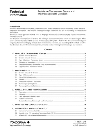
- 3. 1TI 6B0A1-01E 1. Resistance Thermometer Sensors Resistance thermometer sensors (RTSs) are temperature sensors that make use of the physical property where electrical resistance in metal increases proportionally with an increase in temperature. Since platinum RTSs can be expected to provide the most accurate temperature measurement of all industrial temperature sensors, they are widely used, especially in conditions near room temperature. One of the requirements for an industrial thermometer sensor is that its performance and characteristics be guaranteed by a standard. Platinum RTSs have been standardized under JIS C 1604 ("Resistance Thermometer Sensors") and JIS C 1606 ("Sheathed Resistance Thermometer Sensors") in Japan, and standardized under IEC-751 ("Indus- trial Platinum Resistance Thermometer Sensors") abroad. These standards were recently revised one after another. This document explains the revisions and summarizes the essential data based on the new standards. 1.1 Overview of the IEC Revisions IEC-751 was revised in July, 1995. The major change in this revision is to revise reference resistance in accordance with the temperatures of the 1990 International Temperature Scale (ITS-90). ITS-90 has adopted as the new International Temperature Scale since January 1, 1990 (Refer to 5. International Temperature Scale of this document). IEC had started study to revise IEC-751 reference resistance immediately after ITS-90 adoption, and finally accomplished. 1.2 Overview of the JIS Revisions Resistance thermometer sensors JIS was revised in February, 1997. This revision made JIS C 1604 completely conform to IEC-751. The major changes are as follows. (1) JIS for Resistance thermometer sensors is uniformed to JIS C 1604 (Resistance thermometer sensors) and JIS C 1606 (Sheathed resistance thermometer sensors) is abolished. (2) Reference resistance table is revised to conform to IEC standard. In the new JIS, reference resistance table is revised in accordance with the temperatures of the 1990 International Temperature Scale (ITS-90) which is adopted in IEC standard. As for the new resistance reference resistance table, refer to Table A5 Resistance table at the end of this document. Figure 1 shows the difference between reference resistance values of JIS'89 Pt100 and those of JIS'95 Pt100. For example, when the measured temperature is 100˚C, the difference is +0.027˚C, at 300˚C, it is +0.083˚C and at 500˚C, 0.242˚C. This difference is bigger than the temperature difference between the old International Temperature Scale (IPTS-68) and ITS-90 (Refer to 5.3 Influence of ITS-90 on Industrial Thermometers). Comparing the temperature differences to the tolerances at measured value 500˚C, it is about one fifth of the tolerance in class A, and less than one tenth in class B, so their influence can be ignored on a practical industrial use level. However, in using digital device which resolution is 0.1˚C or less than that, the influence cannot be ignored. (3) JPt100, which has used for many years in Japan, is abolished. JPt100, which has unique reference resistance values of Japan, is abolished in the new JIS. With regard to JPt100, it was already announced that it would be abolished in the future at the last time revision (January, 1989). However, considering the
- 4. TI 6B0A1-01E2 situation that they have been used for more than thirty years and many of them are still in use, the 1989 reference resistance table remains in the guide. It is also described in the guide that the characteristics of JPt100 are almost the same as those of Pt100 so that the quality of supplement is guaranteed. This Technical Information provides reference resistance tables of abolished JPt100, JIS'89 Pt100 and JIS'91 50Ω(Pt50) for reference. 0.45 0.40 0.35 0.30 0.25 0.20 0.15 0.10 0.05 0.00 0 50 100 150 200 250 300 350 400 450 500 550 600 650 700 t/˚C ∆t/˚C
- 5. 3TI 6B0A1-01E 1.3 Types of Resistance Thermometer Sensors The types of RTSs specified in JIS C 1604 and JIS C 1606 are standardized, as shown in Table 2, according to the standard resistance element R100/R0 value, Class, rated current, operating temperature range, and lead wire system. Table 1 Resistance Thermometer Sensors (JIS C 1604-1989, JIS C 1606-1989) edoC eulav0R/001R ssalC tnerrucdetaR erutarepmetgnitarepO egnar metsyseriwdaeL 001tP 0583.1 AssalC BssalC Am1 Am2 *Am5 L M H C˚001ot002- C˚053ot0 C˚056ot0 *eriw-2 eriw-3 eriw-4 )001PJ( )6193.1( AssalC BssalC Am1 Am2 *Am5 L M H C˚001ot002- C˚053ot0 C˚056ot0 *eriw-2 eriw-3 eriw-4 :etoN 001taeulavecnatsiserehtsi001R.1 ° .C 001foeulavecnatsiserehtsi0R.2 Ω fota ° .C .deunitnocsidsisesehtnerapnimetinA.3 .AssalCniylppatonod*nahtiwdekramsmetI.4 005+ot0siHegnarerutarepmetgnitareposSTRdehtaehS.5 ° .C .sSTRdehtaehsotelbacilppatonsimetsyseriwdaeleriw-2ehT.6 1.4 Tolerances vs. Temperature Tolerances with respect to temperature must be within the ranges in Table 3 throughout the operating temperature ranges. Table 4 shows samples of tolerance versus measured temperature. If the measured temperature t °C in Table 3 includes a fractional value below the decimal point, the tolerance range includes the smaller value. To avoid the risk of disputes in judgment as a result of exceeding measurement capability, the following guidelines are used for rounding off the tolerances: In Class A the number of valid significant digits below the decimal point is two, rounded down from three. In Class B the number of valid significant digits below the decimal point is one, rounded down from two. Table 2 :stinU °C ssalC ecnareloT AssalC ± )|t|200.0+51.0( BssalC ± )|t|500.0+3.0( Note 1: The error in the measured temperature of the resistance element is the measured temperature subtracted from the temperature computed from the resistance value displayed by the resistance element according to Appendix Table A1 ro Appendix Table A2. Note 2: |t| is the absolute value of the measured temperature (°C), irrespective of the + or – sign. Note 3: Although old JIS Class 0.15 has been discontinued, Yokogawa will sell it, but for the JPt100 only. Tolerance for old JIS Class 0.15 is + (0.15+0.0015 t), and applies over the temperature range of 0 to +350 °C.
- 6. TI 6B0A1-01E4 Table 3 :stinU °C erutarepmetderusaeM ecnareloT AssalC BssalC 002- ± 55.0 ± 3.1 001- ± 53.0 ± 8.0 0 ± 51.0 ± 3.0 001 ± 53.0 ± 8.0 002 ± 55.0 ± 3.1 003 ± 57.0 ± 8.1 004 ± 59.0 ± 3.2 005 ± 51.1 ± 8.2 006 ± 53.1 ± 3.3 056 ± 54.1 ± 6.3 Note: 1. The error in the measured temperature of the resistance element is the measured temperature subtracted from the temperature computed from the resistance value displayed by the resistance element according to Appendix Table A1 ro Appendix Table A2. 2. |t| is the absolute value of the measured temperature (°C), irrespective of the + or – sign. 3. Although old JIS Class 0.15 has been discontinued, Yokogawa will sell it, but for the JPt100 only. Tolerance for old JIS Class 0.15 is + (0.15+0.0015 t), and applies over the temperature range of 0 to +350 °C. Table 4 Temperature/Resistance Characteristics of Resistance Thermometer Sensors (erutarepmeT ° )C 001tPJ98'SIJ 001tP,98'SIJ 001tP5991-157CEI 002- 41.71 94.81 25.81 001- 75.95 52.96 62.06 0 00.001 00.001 00.001 001 61.931 05.831 15.831 002 31.771 48.571 68.571 003 39.312 20.212 50.212 004 65.942 40.742 90.742 005 20.482 09.082 89.082 006 82.713 95.313 17.313 007 31.543 82.543 008 15.573 07.573 elbaTecnatsiseRdradnatS 6A,2AxidnappA 1AxidneppA 5A,4AxidneppA :etoN desivereblliw4061CSIJ,egnahcsihtotmrofnocoT.5991,yluJnidesiversawelbatecnatsiserdradnatS157CEI .noos 1.5 Temperature/Resistance relationships Values in Various Nations Table 5 shows a comparison of resistance thermometer characteristics. IEC standards were standardized in Pub 751 in 1983. Due to intensifying international influence, JIS was revised to accept these in January of 1989. Note that there are significant differ- ences between JPt100 and Pt100.
- 7. 5TI 6B0A1-01E 1.6 Copper Resistance Thermometer Sensors There are no standards for copper RTSs in JIS, and they have been little used in general industry, but they are found in rotating electrical equipment, primarily to measure temperatures of coils, bearings, etc. The following shows the nominal resistances and the standard resistance element Rt/Ro standardized in JEM 1252 (Japan Electrical Manufacturers’ Association) for RTSs in rotating electrical equipment. Table 5 Nominal Resistance foepyT ecnatsiser tnemele lanimoN ecnatsiser dradnatS erutarepmet DTRreppoC 01 Ω 52 °C 52 Ω 0°C Table 6 Standard Resistance Element Rt/Ro Copper Resistance Thermometer Sensors erutarepmeT °C oR/tR erutarepmeT °C oR/tR 0 0000.1 09 5283.1 01 5240.1 001 0524.1 02 0580.1 011 5764.1 52 2601.1 021 0015.1 03 5721.1 031 5255.1 04 0071.1 05 5212.1 06 0552.1 07 5792.1 08 0043.1
- 8. TI 6B0A1-01E6 2. THERMOCOUPLES Thermocouples sense temperatures based on the principle that an electrical current is generated when two different metals are combined in a closed circuit and subjected to a temperature difference; they are widely exploited in industry due to their simple con- struction and excellent reliability. There are many types of thermocouples in use. Those which are the most widely used, whose characteristics are understood, and which have demonstrated their reliability, have become the objects of standardization. This document deals primarily with those thermocouples standardized in the JIS, plus other typically used thermocouples that have been field-proven in particular applications. 2.1 Overview of the JIS '95 Revisions JIS standards related to thermocouples were revised as of July 1, 1995. The major purpose of this revision is to make these JIS standards conform to the international standard IEC 584. Thermocouple codes, thermal EMF, and tolerance classes were revised to match IEC584, so JIS standard data are consistent with the standards used abroad now. The major changes are "N thermocouple is newly stipulated" and "standard thermal EMFs revised". As shown in Figure 1, the difference between JIS'89 and JIS'95 thermal EMFs will have little effect on industrial temperature measurement. Figure 1 Revised Value of Thermal EMF
- 9. 7TI 6B0A1-01E 2.2 Types of Thermocouples In most cases, a thermocouple’s type is indicated by a code. Since the codes specified in JIS conform to the IEC standards, they are shared with other international standards, in particular with DIN (Germany) and ANSI (United States) [See Table 10]. Table 8 shows the codes, component materials, operating limits, and other features of thermo- couples standardized in JIS. Table 9 shows representative non-JIS-standard-thermo- couples in practical use.
- 10. TI 6B0A1-01E8 Table 7 Thermocouple Codes, Component Materials, Normal Operating Limits, and Overheat Operating Limits (JIS C 1602-1981) edoC dlO edoc slairetamtnenopmoC ssalC tnemelE retemaid )mm( lamroN gnitarepo (stimil ° )C taehrevO gnitarepo (stimil ° )C seitreporP edis+ edis– B – %03sniatnoC .muidohR -munitalP yollamuidohR %6sniatnoC .muidohR -munitalP yollamuidohR 2ssalC 3ssalC 05.0 0051 0071 yrevsiFMElamrehT moortallams .erutarepmet nisecnereffidegraL scitsiretcarahc .neessemitemos saemasehtesiwrehtO .RepyT R – %31sniatnoC .muidohR .munitalP yollamuidohR munitalP 2ssalC 05.0 0041 0061 saelbatiuS.elbatsyreV .elpuocomrehtdradnats evisorrocrofelbatiuS .stnemnorivne ,negordyhotevitisneS llamS.sropavlatem yreV.FMElamreht .egnahcralucesthgils eriwnoisnetxeegraL .rorre S – %01sniatnoC .muidohR .munitalP yollamuidohR munitalP 05.0 0041 0061 N yliramirp,yollA ,emorhC,lekciN nociliSdna yliramirp,yollA dna,lekciN nociliS 1ssalC 2ssalC 3ssalC 56.0 058 009 noisorroctnellecxE semitlareves(ecnatsiser oN.)KepyTfotaht oteudnoitarenegrorre .gniredroegnar-trohs dleifcitengaM ylevitalerecneulfni .llams 00.1 059 0001 06.1 0501 0011 03.2 0011 0511 02.3 0021 0521 K AC yliramirp,yollA dnalekciN emorhC yliramirp,yollA lekciN 1ssalC 2ssalC 3ssalC 56.0 056 058 .ytiraenilFMEdooG enisorrocrofelbatiuS tnatsiseR.tnemnorivne .sropavlatemot .egnahcralucesemoS 00.1 057 059 06.1 058 0501 03.2 009 0011 02.3 0001 0021 E CRC yliramirp,yollA dnalekciN emorhC yliramirp,yollA dnareppoC lekciN 1ssalC 2ssalC 3ssalC 56.0 054 005 epyTnahttsocrewoL .FMElamrehtregral,K emoS.citengam-noN .emitrevotfird 00.1 005 055 06.1 055 056 03.2 006 057 02.3 007 008 J CI norI yliramirp,yollA dnareppoC lekciN 1ssalC 2ssalC 3ssalC 56.0 004 005 ylriafhtiw,tsocwoL .FMElamrehtegral .ytiraenilFMEdooG gnicuderrofelbatiuS egraL.stnemnorivne elpmas-ot-elpmas nisnoitairav .ytilauq,scitsiretcarahd tastfirD.ylisaestsuR .serutarepmethgih 00.1 054 055 06.1 005 056 03.2 055 057 02.3 006 057 T CC reppoC yliramirp,yollA dnareppoC lekciN 1ssalC 2ssalC 3ssalC 23.0 002 052 dooghtiw,tsocwoL erutarepmet-wol dooG.scitsiretcarahc rofelbatiuS,ytiraenil .stnemnorivnegnicuder eriwnoisnetxeegraL .rorre 56.0 002 052 00.1 052 003 06.1 003 053
- 11. 9TI 6B0A1-01E Table 8 Non-JIS Thermocouples in practical Use emaN slairetamtnenopmoC gnitarepO erutarepmet taehrevOegnar )(nitimil seitreporP FMElamrehtdradnatS ytirohtuadna,elbat edis+ edis- -munitalP muidohR %02sniatnoC .muidohR -ohR-munitalP yollamuid %5sniatnoC .muidohR -ohR-munitalP yollamuid 0051ot003 °C 0081( ° )C .serutarepmethgihtaelbasU .FMElamrehtllamS .RepyTsaemas,esiwrehtO 22BelbaTxidneppA %04sniatnoC .muidohR -ohR-munitalP yollamuid %02sniatnoC .muidohR -ohR-munitalP yollamuid 0061ot0011 °C 0081( ° )C -netsgnuT muinehR %5sniatnoC .muidohR -ohR-munitalP yollamuid %62sniatnoC .muidohR -ohR-munitalP yollamuid 0042ot0 °C 0003( ° )C gnicuderrofelbatiuS ,sessagtreni,stnemnorivne .eligarF.sagnegordyh 02BselbaTxidneppA 48-889EMTSA %3sniatnoC .muidohR -ohR-munitalP yollamuid %52sniatnoC .muidohR -ohR-munitalP yollamuid 22BelbaTxidneppA 48-889EMTSA netsgnuT %62sniatnoC .muidohR -ohR-munitalP yollamuid lenitalP ,yollA yliramirp ,muidallaP dna,muitalP dloG ,yollA dloGyliramirp muidallaPdna 0011ot0 °C 0031( ° )C .noisarbaotecnatsiserhgiH ehtylraenFMElamrehT .KepyTfotahtsaemas SBN22BelbaTxidneppA .lov,hcraeseRfolanruoJ 80N.C86 /lemorhC norI-dloG ,yollA yliramirp dnalekciN 0?4oemorhC )lemorhC( 70.0sniatnoC .norI%elom yollanorI-dloG K003ot1 ylevitalerFMElamrehT .wolebdnaK02taegral .ytiraenilFMEdooG 034TPSMTSA 12BelbaTxidneppA
- 12. TI 6B0A1-01E10 2.3 Thermal EMF Characteristics The standard thermal EMFs of the various thermocouple types are shown in Appendix Tables B1 through B19. Because JIS C 1602-1995 was written to be consistent with the standards used in other countries, particularly IEC, ANSI, etc., this is beneficial when importing and exporting. However, attention is required since the DIN standard adopts its own unique specifica- tions for Type U and Type L. Table 10 gives a list of the standard thermal EMF document selections for the individual national and international standards. Equations for interpolation of standard thermal EMFs are provided for reference at the end of this document. Table 9 Thermal EMF Document Selection List cirenegelpuocomrehT eman noitangixeddradnatselpuocomrehT FMElamrehtdradnatS rebmuntnemucod skrameRepytdradnatS SIJ CEI ISNA SB NID 03-6/muidohR-munitalP BEPYT 1B-elbaTxidceppA munitalP/muidohR-munitalP REPYT 2B-elbaTxidneppA SEPYT 3B-elbaTxidneppA )N(lisiN/lisorhciN NEPYT 4B-elbaTxidneppA lemulA/lemorhC KEPYT 5B-elbaTxidneppA natnatsnoC-lemorhC EEPYT 6B-elbaTxidneppA natnatsnoC-norI JEPYT 7B-elbaTxidneppA – LepyT )iNuC-eF( 91B-elbaTxidneppA natnatsnoC-reppoC TEPYT 8B-elbaTxidneppA – UepyT )iNuC-uC( 81B-elbaTxidneppA :etoN emasehthcihwrofesohT.dradnatstehtniderevoctonsinoitseuqnielpuocomrehtehttahtsetacidnielbatehtninwardenilA.1 .tnereffiderasemanriehtfinevesFMElamrehtdradnatsemasehtevahnevigsirebmuntnemucod .39-032EMTSA:..F.M.Elamrehtecnereferelpuocomrehtsetalugerhcihw.S.Uehtfodradnatslanoitanasi39'MTSA.2
- 13. 11TI 6B0A1-01E 2.4 Tolerance Tolerances with respect to temperature are shown in Table 11: Table 10 Thermocouple Tolerances (JIS C 1602-1995) sepyT 1ssalcecnareloT 2ssalcecnareloT 3ssalcecnareloT BepyT egnarerutarepmeT eulavecnareloT egnarerutarepmeT eulavecnareloT - - - - - - 0071otC˚006 °C ± 5200.0 • |t| 006 ° 008otC °C C˚4+ 008 ° 0071otC °C ± 500.0 • |t| SepyT,RepyT egnarerutarepmeT eulavecnareloT egnarerutarepmeT eulavecnareloT 001otC˚0 °C ±1°C 0011 ° 0061otC °C ± 300.0+1[ ])0011-t( °C 0° 006+otC °C ± 5.1 °C 0061otC˚006 °C ± 5200.0 • |t| - - - - NepyT,KepyT egnarerutarepmeT eulavecnareloT egnarerutarepmeT eulavecnareloT 04- ° 573otC °C ± 5.1 °C 573 ° 0001otC °C ± 400.0 • |t| 04- ° 333+otC °C ± 5.2 °C 333 ° 0021otC °C ± 5700.0 • |t| 761- ° 04+otC °C ± C˚5.2 002- ° 761-otC °C ± 510.0 • |t| EepyT egnarerutarepmeT eulavecnareloT egnarerutarepmeT eulavecnareloT 04- ° 573+otC °C ± 5.1 °C 573 ° 008otC °C ± 400.0 • |t| 04- ° 333+otC °C ± 5.2 °C 333 ° 009otC °C ± 5700.0 • |t| 761- ° 04+otC °C ± 5.2 °C 002- ° 761-otC °C ± 510.0 • |t| JepyT egnarerutarepmeT eulavecnareloT egnarerutarepmeT eulavecnareloT 04- ° 573+otC °C ± 5.1 °C 573 ° 057otC °C ± 400.0 • |t| 04- ° 333+otC °C ± 5.2 °C 333 ° 057otC °C ± 5700.0 • |t| - - - - TepyT egnarerutarepmeT eulavecnareloT egnarerutarepmeT eulavecnareloT 04- ° 521+otC °C ± 5.0 °C 521 ° 053otC °C ± 400.0 • |t| 04- ° 331+otC °C ±1°C 331 ° 053otC °C ± 5700.0 • |t| 76- ° 04+otC °C ±1°C 002- ° 76-otC °C ± 510.0 • |t| :etoN nideificepssecnarelotgnirutcafunamehtteemotdeilppusyllameoneraslairetamelpuocomrehT.1 ehtnihtiwllaftonyam,revewoh,slairetamesehT.C˚04-evobaserutarepmetrofelbateht fI.NdnaK,E,Tsepytrof3ssalcrednunevigserutarepmetwolrofsecnarelotgnirutcafunam resahcrupeht2ro1ssalcfoesohtsallewsa,3ssalcfostimilteemrofderiuqereraselpuocomreht .deriuqeryllaususislairetamfonoitcelessa,sihtetatsllahs 2.5 Themocouple Electrical Characteristics Electrical characteristics is as shown in Table 12. Insulation resistance is applied to routine unit test. Dielectric strength is applied to type test. Table 11 Electrical Characteristics metI scitsiretcarahC otdeilppaylnO(ecnatsisernoitalusnI )ebutnoitcetorphtiwselpuocomreht slanimretneewtebecnatsisernoitalusnI nahteromsiebutnoitcetorpdna CDV005/WM01 otdeilppaylnO(htgnertscirtceleiD )ebutnoitcetorphtiwselpuocomreht etunimenorofCAV005
- 14. TI 6B0A1-01E12 2.6 Thermocouple operating Limits Normal operating limits are the temperatures that are generally recommended for continuous use in air. Overheat operating limits are the temperatures for short-period use not sharply defined limiting temperatures, but rather those at which operations for the times indicated in Table 13 will not result in thermal EMF changes greater than the values also shown in that table for continuous operation in clean air. Table 12 Thermocouple Continuous-Operation Times edoC )h(emitnoitarepo-suounitnoC ynata)%(egnahcFMElamrehT timilerutarepmetgnitarepolamrontA timil gnitarepotaehrevotA B R S N K E J T 0002 0002 0002 00001 00001 00001 00001 00001 05 05 05 052 052 052 052 052 ± 5.0 ± 5.0 ± 5.0 ± 57.0 ± 57.0 ± 57.0 ± 57.0 ± 57.0
- 15. 13TI 6B0A1-01E 2.7 Thermocouple Leadwire Resistances Although electronic instruments almost unaffected by thermocouple leadwire resistance, it can cause problems in the case of moving coil instruments and may require compensa- tion, so the user should follow any directions given in the manual for the instrument. Table 14 shows thermocouple resistance R0 at 0˚C, and resistance R20 at 20˚C. Table 15 shows the resistance ratios Rt/R20 and Rt/R0, between resistance values R20 and R0 and resistance value Rt at t˚C. When compensating for this resistance with moving-coil instruments, it is customary to treat half of the thermocouple’s specified length as being at the operating temperature, and the other half as the room temperature. Table 13 Thermocouple Resistances Code for component materials B R S K E J T N Old code (reference) - - - CA CRC IC CC - Wire diameter in mm 0.32 - - - - - - 6.17 - 0.50 1.75 1.47 1.43 - - - - - 0.65 - - - 2.95 3.56 1.70 1.50 3.94 1.00 - - - 1.25 1.50 0.72 0.63 1.66 1.60 - - - 0.49 0.59 0.28 0.25 0.65 2.30 - - - 0.24 0.28 0.14 - 0.31 3.20 - - - 0.12 0.15 0.07 - 0.16 Unit: Ω/m Table 14 Thermocouple Resistance Ratios (Rt/R0 and Rt/R20) Code B R S K E J T N Old code – – CA CRC IC CC – Temperature (t) ˚C Rt/R0 Rt/R20 Rt/R0 Rt/R20 Rt/R0 Rt/R20 Rt/R0 Rt/R20 Rt/R0 Rt/R20 Rt/R0 Rt/R20 Rt/R0 Rt/R20 Rt/R0 0 1.00 0.97 1.00 0.95 1.00 0.95 1.00 0.98 1.00 1.00 1.00 0.98 1.00 1.00 1.00 20 1.03 1.00 1.05 1.00 1.05 1.00 1.02 1.00 1.01 1.00 1.02 1.00 1.00 1.00 1.02 100 1.17 1.13 1.24 1.17 1.25 1.17 1.10 1.08 1.02 1.02 1.10 1.08 1.01 1.01 1.15 200 1.34 1.29 1.46 1.40 1.48 1.39 1.18 1.16 1.05 1.05 1.22 1.19 1.02 1.02 300 1.50 1.45 1.68 1.61 1.71 1.61 1.26 1.23 1.08 1.08 1.34 1.34 1.03 1.03 400 1.65 1.60 1.94 1.85 1.97 1.83 1.32 1.29 1.11 1.11 1.55 1.52 500 1.80 1.74 2.12 2.02 2.16 2.03 1.37 1.34 1.13 1.13 1.78 1.74 600 1.95 1.88 2.32 2.22 2.37 2.23 1.41 1.38 1.16 1.15 2.04 2.00 700 2.10 2.03 2.52 2.41 2.58 2.43 1.45 1.42 1.18 1.18 2.35 2.30 800 2.25 2.17 2.72 2.60 2.75 2.61 1.50 1.47 1.20 1.20 2.69 2.44 900 2.39 2.31 2.90 2.78 2.97 2.80 1.54 1.51 1000 2.53 2.45 3.04 2.95 3.16 2.97 1.59 1.56 1100 2.66 2.57 3.26 3.12 3.34 3.14 1.64 1.61 1200 2.79 2.70 3.43 3.28 3.52 3.30 1.68 1.65 1300 2.92 2.82 3.59 3.44 3.68 3.46 1400 3.04 2.94 3.75 3.59 3.85 3.62 1500 3.16 3.06 3.90 3.73 4.00 3.77 1600 3.28 3.17 1700 3.40 3.29
- 16. TI 6B0A1-01E14 3. MINERAL INSULATED THERMOCOUPLES 3.1 Construction Mineral Insulated thermocouples are filled with a powdered inorganic insulator (Mgo) between the metal sheath and the thermocouple element, and are of a single construc- tion. Table 16 shoes the dimensions of Mineral Insulated thermocouples. Table 15 Mineral Insulated Thermocouple Dimensions mm:tinU htaehslateM Dretemaidretuo tnemeleelpuocomrehT dretemaid tssenkcihthtaehslateM 0.1 ± 50.0 6.1 ± 50.0 2.3 ± 50.0 8.4 ± 50.0 4.6 ± 50.0 0.8 ± 50.0 latemfoeromro%51 retemaidretuohtaehs latemfoeromro%01 retemaidretuohtaehs Figure 2 Cross Section of Mineral Insulated Themocouple (1) Longitudinal section of the measuring junction of an earthed thermocouple (2) Longitudinal section of the measuring junction of an insulated thermocouple Figure 3 Constructions of Measuring Junctions
- 17. 15TI 6B0A1-01E 3.2 Tolerances Table 16 shows tolerances. These are determined in conformance with those for general thermocouples. Table 16 Tolerance classes for thermocouples (reference junction at 0˚C) epyT ecnareloT 1ssalc ecnareloT 2ssalc ecnareloT 3ssalc TepyT egnarerutarepmeT eulavecnareloT egnarerutarepmeT eulavecnareloT 04- ° 52+otC °C ± 5.0 °C 521 ° 053otC °C ± 400.0 • |t| 04- ° 331+otC °C ±1°C 331 ° 053otC °C ± 5700.0 • |t| 76- ° 04+otC °C ±1°C 002 ° 76-otC °C ± 510.0 • |t| EepyT egnarerutarepmeT eulavecnareloT egnarerutarepmeT eulavecnareloT 04- ° 573+otC °C ± 5.1 °C 573 ° 008otC °C ± 400.0 • |t| 04- ° 333+otC °C ± 5.2 °C 333 ° 009otC °C ± 5700.0 • |t| 761- ° 04+otC °C ± 5.2 °C 002- ° 761-otC °C ± 510.0 • |t| JepyT egnarerutarepmeT eulavecnareloT egnarerutarepmeT eulavecnareloT 04- ° 573+otC °C ± 5.1 °C 573 ° 057otC °C ± 400.0 • |t| 04- ° 333+otC °C ± 5.2 °C 333 ° 057otC °C ± 5700.0 • |t| – – – – NepyT,KepyT egnarerutarepmeT eulavecnareloT egnarerutarepmeT eulavecnareloT 04- ° 573+otC °C ± 5.1 °C 573 ° 0001otC °C ± 400.0 • |t| 04- ° 333+otC °C ± 5.2 °C 333 ° 0021otC °C ± 5700.0 • |t| 761- ° 04+otC °C ± 5.2 °C 002- ° 761-otC °C ± 510.0 • |t| :etoN tnemerusaemehtgnitcartbusybdetaluclacecnereffidehtroftimilmumixamehtsiecnarelotehT)1( dradnatsehtgnisuFMElamrehtehtmorfdetrevnocerutarepmetehtmorferutarepmetnoitcnuj foregralehtsiecnarelotehT.elbatFMElamreht ° %roC nideificepssecnarelotgnirutcafunamehtteemotdeilppusyllameoneraslairetamelpuocomrehT)2( 04-evobaserutarepmetrofelbateht ° ehtnihtiwllaftonyam,revewoh,slairetamesehT.C fI.NdnaK,E,Tsepytrof3ssalcrednunevigserutarepmetwolrofsecnarelotgnirutcafunam resahcrupeht2ro1ssalcfoesohtsallewsa,3ssalcfostimilteemrofderiuqereraselpuocomreht .deriuqeryllaususislairetamfonoitcelessa,sihtetatsllahs
- 18. TI 6B0A1-01E16 3.3 Codes and Normal Operating Limits The code for a Mineral Insulated thermocouple is the same as that for a regular thermo- couple with an S added at the beginning . Table 14 shows the normal operating limits for Mineral Insulated thermocouples. The codes for the materials used for the sheath are as follows: A : Austenitic stainless steel (SUS 347, SU S316) B : Nickel-Chromium heat-resistant alloy (Inconel) Table 17 Normal Operating Limits for Mineral Insulated Thermocouples (JIS C 1605- 1995) edoC retemaiDretuOhtaehS mm htaehSlateM °C A B NS 5.0 006 0.2,)6.1(,5.1,0.1 056 )2.3(,0.3 057 )8.4(,5.4 008 009 )8.4(,5.4 008 009 )4.6(,0.6 008 0001 0.8 009 0501 KS 5.0 006 0.2,)6.1(,5.1,0.1 056 )2.3(,0.3 057 )8.4(,5.4 008 009 )4.6(,0.6 008 0001 0.8 009 0501 ES 5.0 006 0.2,)6.1(,5.1,0.1 056 )2.3(,0.3 057 )8.4(,5.4 008 009 )4.6(,0.6 008 009 0.8 008 009 JS 5.0 004 0.2,)6.1(,5.1,0.1 054 )2.3(,0.3 056 )8.4(,5.4 057 )4.6(,0.6 057 0.8 057 TS 5.0 003 0.2,)6.1(,5.1,0.1 003 )2.3(,0.3 053 )8.4(,5.4 053 )4.6(,0.6 053 0.8 053 Notes: 1. The normal operating limit is the temperature at which the device can be used continuously in air. 2. The normal operating limits differ from those in JIS C 1602 due to the large dependence on the heat- resistance of the metal sheath. 3. ( ) will be removed in the future.
- 19. 17TI 6B0A1-01E 3.4 Electrical Characteristics (Insulation Resistance, Thermocouple Leadwire Resistance) Insulation resistances and thermocouple leadwire resistances are as shown in Table 19. Table 20 shows sheathed thermocouple leadwire resistances. Due to the large variations in sheathed thermocouple leadwire resistances, no standards are prescribed. Table 20 presents some examples for reference: Table 18 Electrical Characteristics metI retuOhtaehSlateM )mm(retemaiD scitsiretcarahC ecnatsisernoitalusnI 0.2,)6.1(,5.1,0.1,5.0 M02> Ω CDV001/ ,0.6,)8.4(,5.4,)2.3(,0.3 0.8,)4.6( M001> Ω CDV005/ htgnertscirtceleiD )6.1(,5.1,0.1 etunimenorofCAV001 ,0.6,)8.4(,5.4,)2.3(,0.3 0.8,)4.6( etunimenorofCAV005 Notes: (1) These tests should not be applied to earthed thermocouples. (2) For thermocouples with compensating cable, apply the smaller of the above values or insulation resis- tances regulated in JIS C 1610. (3) ( ) will be removed in the future. Table 19 Mineral insulated Thermocouple Leadwire Resistances Sheath Outer diameter (mm) SK SJ ST SE Standard resistance Maximum resistance Standard resistance Maximum resistance Standard resistance Maximum resistance Standard resistance Maximum resistance 219.49 – – – – – – – 1.0 40.32 55.22 23.81 32.44 – – – – 1.6 16.34 19.75 9.65 11.65 7.94 9.61 – – 3.2 3.15 3.74 1.87 2.2 1.61 1.90 3.77 4.46 4.8 1.40 1.50 0.84 0.93 0.70 0.78 1.70 1.80 6.4 0.79 0.89 0.48 0.54 0.40 0.45 0.94 1.10 8.0 0.66 0.73 0.38 0.44 0.32 0.37 0.77 0.87 2.2 16.31 19.8 – – – – – – 3.2 7.72 8.79 4.60 5.20 3.80 4.40 – – 4.8 3.43 4.08 2.10 2.50 1.70 2.10 – – 6.4 1.93 2.20 1.20 1.30 0.94 1.10 – – 8.0 1.24 1.44 0.75 0.82 1.63 0.69 1.48 1.73 Unit: Ω/m Note: Resistance dispersion is ±20%
- 20. TI 6B0A1-01E18 4. EXTENTION AND COMPENSATING CABLE Table 21 shows the types (codes), component materials, operating temperatures, toler- ances and colors for compensating cable. In the revision of JIS C1610 (Compensating cable) of July 1995, types (codes), operating temperatures, tolerances, and colors were changed. Especially for the color of the cable cover, Division 1 is newly added to conform to IEC standard. However, the former JIS color regulation still remains as Division 2 so as not to cause accidents due to the color change when expanding or retrofitting existing systems. Use Division 2 as necessary. Usage classification is shown in Table 22. Since operating temperature high limit extended to 200˚C, FEP (teflon) is newly added to insulator types. As usage classifica- tion is determined by insulator material, conditions are described in the notes of Table 22. Table 23 shows insulator resistance. Standard values differ according to the materials. Table 20 Compensating Cable Characteristics fosepyT CT denibmoc elbaCgnitasnepmoC sepyT slairetaMtnenopmoC egnar.pmeT )ecnarelotrof( (° )C ecnareloT (µ )V edoCroloCecafruS edoC edoC edoCdlO edis+ edis- 1ssalC 2ssalC 1.viD 2.viD B CB XB reppoC reppoC 001ot0 – – yarG yarG R ACR XR reppoC yliramirp,yollA dnareppoC lekciN 001ot0 – Ϯ 03 egnarO kcalB BCR 001ot0 – Ϯ 06 S ACS XS 001ot0 – Ϯ 03 egnarO kcalB BCS 002ot0 – Ϯ 06 N XN – yliramirp,yollA dnalekciN emorhC yliramirp,yollA dnalekciN nociliS 002ot52– Ϯ 06 Ϯ 001 kniP – CN – yliramirp,yollA dnareppoC lekciN yliramirp,yollA dnareppoC lekciN 051ot0 – Ϯ 001 K XK XK yliramirp,yollA dnalekciN emorhC yliramirp,yollA lekciN 002ot52– Ϯ 06 Ϯ 001 neerG eulB ACK – 051ot0 – Ϯ 001 BCK XW nocI yliramirp,yollA dnareppoC lekciN 051ot0 – Ϯ 001 CCK XV reppoC yliramirp,yollA dnareppoC lekciN 001ot0 – Ϯ 001 E XE XE yliramirp,yollA dnalekciN emorhC yliramirp,yollA dnareppoC lekciN 002ot52– Ϯ 021 Ϯ 002 elpruP elpruP J XJ XJ norI yliramirp,yollA dnareppoC lekciN 002ot52– Ϯ 58 Ϯ 041 kcalB wolleY T XT XT reppoC yliramirp,yollA dnareppoC lekciN 001ot52– Ϯ 03 Ϯ 06 nworB nworB gnitarepoelbacrofsadna,srotcudnocfoecnarelotehtnihtiwebdluohstniopnoitasnepmocnoitcnuj-ecnereferehttaerutarepmetehT:etoN .ytiroirprehgihanevigsinoitacifissalcegasu22elbat,egnarerutarepmet
- 21. 19TI 6B0A1-01E Table 21 Usage Classification :tinU °C egasU noitacifssalC edoC dlO edoC foslairetaM rotalusnI gnitarepO erutarepmeT setoN esulareneG G G lyniV 09+ot02- BCSdnaBCRrofelbacilppatoN)1 BCL,ACK,CN,ACS,ACR,CBfoegnarerutarepmetgnitarepO)2 0morfsiCCK ° C 09+ot ° C egnarelddiM H H nrayssalG 051+ot0 .XTroCCK,ACS,ACR,CBrofelbacilppatoN egnarhgiH S – PEF 002+ot52- .srotcudnocgnitasnepmocrofelbacilppatoN)1 52-morfsiXTfoegnarerutarepmetgnitarepO)2 ° 001+otC ° C Table22 Insulator Resistance M:tinU Ω mk• egasU noitacifssalC sedoC foslairetaM rotalusnI noitalusnI ecnatsiseR esulareneG G lyniV 05 egnarelddiM H nrayssalG 50.0 egnarhgiH S PEF 0001 Table 23 Extension and Compensating Cable Resistance elbacnoitnetxE ecnatsiserlacirtcelE tamm56.0,retemaideriwdael( 02 ° ,C Ω )mk/ detsiwtfoecnatsiserlacirtcelE 02tasrotcudnoc °C Ω mk/ seriw7 seriw4 )edis+XT,CCK,CS,CR/sedishtobCB(reppoC 92.55 09.7 42.41 )edis+XJ,BCK(norI 0.844 29.56 4.511 )edis-CS,CR(yollalekciN-reppoC 0.402 20.03 35.25 )edis–XK(lemulA 0.288 0.621 5.022 )edis+XK(lemorhC 1412 8.503 2.535 )edis-XJ(yollalekciN-reppoC 7951 5.332 2.114 )edis+XE(lemorhC 0.288 0.621 5.022 )edis-XE(yollalekciN-reppoC 7951 5.332 2.114 )edis-XT(yollalekciN-reppoC 7951 5.332 2.114 )edis-CCK(yollalekciN-reppoC 7951 5.332 2.114
- 22. TI 6B0A1-01E20 5. INTERNATIONAL TEMPERATURE SCALE 5.1 International Temperature Scale Plan As with other physical quantities, because temperatures must be expressed the same internationally, they are expressed with a temperature scale based on a resolution passed at a general meeting of the International Weights and Measures Committee. The old international temperature scale, the 1968 International Practical Temperatures Scale (IPTS-68), was revised by the 78th International Weights and Measures Commuitee in September of 1989 based on a resolution from the 18th general meeting of the Interna- tional Weights and Measures Committee which met in 1987. The 1990 International Temperature Scale (ITS-90) was adopted as the new international temperature scale, and has been in effect internationally since January 1,1990. These changes in the international temperature scale solved problems found in IPTS-68 through advances in measurement technology centering on the latest thermodynamic temperature measurements. The international temperature scale plan is guided by the following three principles: (1) The plan specifies repeatable thermal equilibrium states, which are assigned tempera- tures to define fixed points. (2) The plan assigns a standard thermometer for each temperature range, calibrated to the defining fixed points. (3) The plan establishes interpolation formulas that decide the relationships between temperatures (international temperatures) and standard thermometer indicated temperatures (output values) in order to interpolate between the defining fixed points. Although the temperature concepts are based on thermodynamic temperatures, since absolute measurement of thermodynamic temperatures is not possible, improvements that bring the international temperature scale closer to thermodynamic temperatures are a matter of repetition along with progress in measurement techniques. Gas and radiation thermometers are used as thermodynamically well-defined thermometers in the measure- ment of thermodynamic temperatures. However, although a gas thermometer in prin- ciple determines thermodynamic temperature from a comparison of pressure at ideal states using ideal gasses, in fact since no ideal gas actually exists and an ideal state cannot be perfectly attained, we can only arrange conditions close to the ideal and add corrections to the best of our ability to determine the true values. Thus, in keeping with progress in measurement techniques, corrections are incorporated into the temperatures of the defining fixed points. Previously, a new international temperature scale had been adopted roughly every twenty years. The ITS-90 now in use has been adopted as an attempt to faithfully arrive at the thermodynamic temperatures using state-of-the-art techniques. However, because advanced techniques were required to achieve ITS-90, these endeavors are entrusted to the techniques of specialists at organizations studying temperature measurements.
- 23. 21TI 6B0A1-01E 5.2 Essentials of the 1990 International Temperature Scale (ITS-90) ITS-90 is intended to solve certain problems found in the 1968 International Practical Temperature Scale (IPTS-68). The main corrections are as follows: (1) The low temperature range is expanded, and is defined to 0.65K. (2) The range previously defined by thermocouples (630.74 to 1064.43˚C) is replaced by a range up to 961.78˚C defined using a platinum resistance thermometer, while the range above 961.78˚C is defined using a radiation thermometer. (3) The defining fixed points have been changed, with the boiling points of oxygen, water, and neon being eliminated and replaced by several triple points and freezing points, and the temperatures at the defining fixed points overall have been changed. The relationship between the defining fixed points of the ITS-90 and the instruments for interpolation is shown in Table 25. Because the temperatures for the defining fixed points have changed overall, the t90-t68 Temperature Difference shown in Table 26 has been changed based on these definition changes Table 24 Comparison of IPTS-68 and ITS-90 Interpolation instrumentsInterpolation instruments T68/K T90/K t90/˚C Helium vapor pressure scale Gas thermometer Platinum resistance thermometer Plank's law of radiation Platinum resistance thermometer Plank's law of radiation S thermocouple -29.3467 -248.5939 -218.7916 -189.3442 -38.8344 0.01 29.7646 156.5985 231.928 419.527 660.323 961.78 1064.18 1084.62 13.81 17.042 20.28 27.102 54.361 83.798 90.188 273.16 373.15 505.1181 692.73 903.9 1235.58 1337.58 He (V) e - H2 (T) (B)e - H2 (V) (B)e - H2 (V) Ne (T) Ne (B) O2 (T) Ar (T) O2 (C) Hg (T) H2O (T) Ga (M) H2O (V) In (F) Sn (F) Zn (F) Al (F) Ag (F) Au (f) Cu (F) 0.65 3 to 5 13.8033 to 17 to 20.3 24.5561 54.3584 83.8058 234.3156 273.16 302.9146 429.7485 505.078 692.677 933.473 1234.93 1337.33 1357.77 Note: Descriptions of defining fixed-point states: B: Boiling point (state of equilibrium between the liquid phase and gas phase at one atmosphere of pressure) C: Condensation point (state of equilibrium between the liquid phase and gas phase at one atmosphere of pressure at which the liquid phase condenses) F: Freezing point (state of equilibrium between the liquid phase and solid phase) M: Melting point (state of equilibrium between the solid phase liquid phase) T: Triple point (state of equilibrium between the solid phase, liquid phase, and gas phase) V: Vapor pressure point (state of equilibrium between the liquid phase and gas phase)
- 24. TI 6B0A1-01E22 5.3 Influence of ITS-90 on Industrial Thermometers Because industrial thermometers conform to JIS, the temperature differences due to definition changes, and their relationship to JIS, are matters of importance. Since the temperature differences accompanying definition changes are small, on a practical level their influence can be ignored (see Figure 4). The areas where the effects of ITS-90 become a problem for the temperature related JIS standards are in the standard thermal EMF tables for thermocouples, and the standard resistance are in the standard thermal EMF tables for thermocouples, and the standard resistance tables for resistance thermometers sensors. Because the temperatures for the current standard tables are regulated by IPTS-68, the switch to ITS-90 requres that these be changed by the temperature difference (t90 - t68). Because the JIS tolerances for temperature sensors are specified with respect to the standard tables, the influence of ITS-90 becomes clear when the temperature differences due to definition changes are compared to the tolerances. The maximum temperature difference due to a definition change in the region up to 1100˚C is + 0.36˚C at 780˚C. The value of this corresponds to 11% of the tolerance (3.1˚C) of a Class 0.4 thermocouple, and can, in practice, be ignored. Although for a Class 0.25 thermocouple the change at 780˚C reaches nearly half of the tolerance, this presents no problems because Class 0.25 applies only to Types R and S thermocouples, and these are usually used at 1000˚C and above. The operating limits for RTSs are 650˚C for Pt100, and 500˚C for JPt100. The largest change in the range up to 650˚C is 0.115˚C at 600˚C; this value is 10% of the tolerance of + 1.35˚C for a Class A type, and can be ignored in practice. Although as explained above there is no problem in viewing the transition to ITS-90 as having no practical effect on industrial thermometry, there are instances in which the application of ITS-90 required for precision measurements such as temperature measure- ment in scientific research for determining physical constants. In such cases, tempera- ture measurements should be converted according to the values in Table 26. accuracy˚C Figure 4 Temperature Difference in International Temperature Scales, and JIS Toler- ances
- 25. 23TI 6B0A1-01E Table 25 Differences Between ITS-90 and IPTS-68
- 26. TI 6B0A1-01E24 APPENDIX TABLE A1-1 PT100 REFERENCE RESISTANCE TABLE This table shows values specified by JIS C 1604-1989 and JIS C1606-1989. ■ Pt100 Resistance thermometer sensor (JIS C1604-1989) (JIS C1606-1989)
- 27. 25TI 6B0A1-01E APPENDIX TABLE A1-2 PT100 REFERENCE RESISTANCES The reference resistances in Appendix Table A1 are calculated in the following equa- tions: -200˚C to 0˚C range: Rt = R0 [1 + At + Bt2 + C (t - 100) t3] 0˚C to + 650 ˚C range: Rt =R0 (1 + At + Bt2) Where: A = 3.90802 x 10⁻³˚C -01 B = -5.802 x 10 - 7˚C - 2 C = -4.2735 x 10 - 12˚C - 4 Notes: 1. R0 is 100Ω, and Rt represents the resistance at t˚C. 2. The above expressions were used to calculate the reference resistances for this standard, and are not intended to be used to determine the characteristics of any individual RTS.
- 28. TI 6B0A1-01E26 APPENDIX TABLE A2-1 JPT100 REFERENCE RESISTANCE TABLE This is the JPt100 reference resistance table defined in JISC1604 and JISC1606. ■ JPt 100RTS (JISC1604-1989) (JISC1606-1989)
- 29. 27TI 6B0A1-01E APPENDIX TABLE A2-2 JPT100 REFERENCE RESISTANCE TABLE ■ JPT100RTS continued from the previous page.
- 30. TI 6B0A1-01E28 APPENDIX TABLE A3-1 RT50 REFERENCE RESISTANCE TABLE Abolished after January 1, 1989. ■ Pt 50 Ω RTS.
- 31. 29TI 6B0A1-01E APPENDIX TABLE A3-2 PT50 REFERENCE RESISTANCE TABLE Abolished after January 1, 1989. ■ Pt 50 Ω (Continued from the previous page)
- 32. TI 6B0A1-01E30 APPENDIX TABLE A4-1 PT100 REFERENCE RESISTANCE TABLE This is the reference resistance table defined in IEC Pub 751-1995. JIS C 1604-1997.
- 33. 31TI 6B0A1-01E APPENDIX TABLE A4-2 PT100 REFERENCE RESISTANCE TABLE
- 34. TI 6B0A1-01E32 APPENDIX TABLE A5 INTERPOLATION EQUATION FOR PT100 REFER- ENCE RESISTANCE The reference resistances in Appendix A4 Pt100 reference resistance table (IEC 751- 1995) are calculated in the following equations; -200˚C to 0˚C range: Rt = Ro [1 + At + Bt2 + C(t - 100)t3 ] 0˚C to 850˚C range: Rt = Ro (1 + At + Bt2 ) Where; A = 3.9083 x 10⁻³ ˚C-1 B = -5.775 x 10⁻⁷ ˚C-2 C = -4.183 x 10⁻¹² ˚C-4 Notes: 1. Ro is 100Ω, and Rt represents the resistance at t˚C. 2. The above expressions were used to calculate the reference resistances for this standard, and are not intended to be used to determine the characteristics of any individual RTS. APPENDIX TABLE A6 INTERPOLATION EQUATION FOR JPT100 REFER- ENCE RESISTANCE The reference resistances in Appendix A2 JPt100 reference resistance table (JIS C 1604-1989) are calculated in the following equations: For 0°C to 630°C range, Rt = Ro (1 + At1 + Bt12 ) (1) Where; A = 0.3974973 x 10⁻² B = -0.58973 x 10⁻⁶ t' is obtained in equation (2) t' = t - 0.045 ( ) ( - 1) ( - 1) ( - 1) (2) For -200°C to 0°C range, Rt = Ro ∑ ai ti (3) Where; a0 = 0 a1 = 3.971686 x 10⁻³ a2 = -1.157433 x 10⁻⁶ a3 = -2.051844 x 10⁻⁸ a4 = -3.629438 x 10⁻¹⁰ a5 = -3.157615 x 10⁻¹² a6 = -1.369914 x 10⁻¹⁴ a7 = -2.303654 x 10⁻¹⁷ Notes: 1. R0 is 100Ω, and Rt represents the resistance at t°C. 2. The tolerance of calculation error in the equation (2) is less than 0.000019°C. 3. The tolerance of calculation error in the equation (3) is less than 0.0035°C. t' 100 t' 100 t' 419.58 t' 630.74 i =7 i =0
- 35. 33TI 6B0A1-01E APPENDIX TABLE B1-1 TYPE B THERMOCOUPLE THERMAL E.M.F. TABLE This is the reference thermal e.m.f. table defined in JIS C1602-1995.
- 36. TI 6B0A1-01E34 C 1602-1995 APPENDIX TABLE B1-2 TYPE B THERMOCOUPLE THERMAL E.M.F. TABLE
- 37. 35TI 6B0A1-01E C 1602-1995 APPENDIX TABLE B1-3 TYPE B THERMOCOUPLE THERMAL E.M.F. TABLE
- 38. TI 6B0A1-01E36 C 1602-1995 APPENDIX TABLE B1-4 TYPE B THERMOCOUPLE THERMAL E.M.F. TABLE Remarks: The temperature at the reference-junction compensation point is set at 0˚C
- 39. 37TI 6B0A1-01E C 1602-1995 APPENDIX TABLE B2-1 TYPE R THERMOCOUPLE THERMAL E.M.F. TABLE This is the reference thermal e.m.f. table defined in JIS C1602-1995
- 40. TI 6B0A1-01E38 C 1602-1995 APPENDIX TABLE B2-2 TYPE R THERMOCOUPLE THERMAL E.M.F. TABLE
- 41. 39TI 6B0A1-01E C 1602-1995 APPENDIX TABLE B2-3 TYPE R THERMOCOUPLE THERMAL E.M.F. TABLE
- 42. TI 6B0A1-01E40 C 1602-1995 APPENDIX TABLE B2-4 TYPE R THERMOCOUPLE THERMAL E.M.F. TABLE Remarks: The temperature at reference-junction compensation point is set at 0˚C.
- 43. 41TI 6B0A1-01E C 1602-1995 APPENDIX TABLE B3-1 TYPE S THERMOCOUPLE THERMAL E.M.F. TABLE This is the reference thermal e.m.f. table defined in JIS C1602-1995.
- 44. TI 6B0A1-01E42 C 1602-1995 APPENDIX TABLE B3-2 TYPE S THERMOCOUPLE THERMAL E.M.F. TABLE
- 45. 43TI 6B0A1-01E C 1602-1995 APPENDIX TABLE B3-3 TYPE S THERMOCOUPLE THERMAL E.M.F. TABLE
- 46. TI 6B0A1-01E44 C 1602-1995 APPENDIX TABLE B3-4 TYPE S THERMOCOUPLE THERMAL E.M.F. TABLE Remarks: The temperature at the reference-junction compensation point is set at 0˚C.
- 47. 45TI 6B0A1-01E C 1602-1995 APPENDIX TABLE B4-1 TYPE N THERMOCOUPLE THERMAL E.M.F. TABLE This is the reference thermal e.m.f. table defined in JIS C1602-1995.
- 48. TI 6B0A1-01E46 C 1602-1995 APPENDIX TABLE B4-2 TYPE N THERMOCOUPLE THERMAL E.M.F. TABLE
- 49. 47TI 6B0A1-01E C 1602-1995 APPENDIX TABLE B4-3 TYPE N THERMOCOUPLE THERMAL E.M.F. TABLE Remarks: The temperature at the reference-junction compensation point is set at 0˚C.
- 50. TI 6B0A1-01E48 C 1602-1995 APPENDIX TABLE B5-1 TYPE K THERMOCOUPLE THERMAL E.M.F. TABLE This is the reference thermal e.m.f. table defined in JIS C1602-1995.
- 51. 49TI 6B0A1-01E C 1602-1995 APPENDIX TABLE B5-2 TYPE K THERMOCOUPLE THERMAL E.M.F. TABLE
- 52. TI 6B0A1-01E50 C 1602-1995 APPENDIX TABLE B5-3 TYPE K THERMOCOUPLE THERMAL E.M.F. TABLE
- 53. 51TI 6B0A1-01E C 1602-1995 APPENDIX TABLE B5-4 TYPE K THERMOCOUPLE THERMAL E.M.F. TABLE Remarks: The temperature at the reference-junction compensation point is set at 0˚C.
- 54. TI 6B0A1-01E52 C 1602-1995 APPENDIX TABLE B6-1 TYPE E THERMOCOUPLE THERMAL E.M.F. TABLE This is the reference thermal e.m.f. table defined in JIS C1602-1995.
- 55. 53TI 6B0A1-01E C 1602-1995 APPENDIX TABLE B6-2 TYPE E THERMOCOUPLE THERMAL E.M.F. TABLE
- 56. TI 6B0A1-01E54 C 1602-1995 APPENDIX TABLE B6-3 TYPE E THERMOCOUPLE THERMAL E.M.F. TABLE Remarks: The temperature at the reference-junction compensation point is set at 0˚C.
- 57. 55TI 6B0A1-01E C 1602-1995 APPENDIX TABLE B7-1 TYPE J THERMOCOUPLE THERMAL E.M.F. TABLE This is the reference thermal e.m.f. table defined in JIS C1602-1995.
- 58. TI 6B0A1-01E56 C 1602-1995 APPENDIX TABLE B7-2 TYPE J THERMOCOUPLE THERMAL E.M.F. TABLE
- 59. 57TI 6B0A1-01E C 1602-1995 APPENDIX TABLE B7-3 TYPE J THERMOCOUPLE THERMAL E.M.F. TABLE Remarks: The temperature at the reference-junction compensation point is set at 0˚C.
- 60. TI 6B0A1-01E58 C 1602-1995 APPENDIX TABLE B8-1 TYPE T THERMOCOUPLE THERMAL E.M.F. TABLE This is the reference thermal e.m.f. table defined in JIS C1602-1995.
- 61. 59TI 6B0A1-01E C 1602-1995 APPENDIX TABLE B8-2 TYPE T THERMOCOUPLE THERMAL E.M.F. TABLE Remarks: The temperature at the reference-junction compensation point is set at 0˚C.
- 62. TI 6B0A1-01E60 C 1602-1995 APPENDIX TABLE B9 INTERPOLATION EQUATION OF REFERENCE THERMAL E.M.F. of JIS'95 (JIS C1602-1995) These equations are applied to Appendix Tables B1 to B8. E: Reference thermal e.m.f. t: Temperature (˚C) Remarks: This table is applied to calculate Appendix table B1 type B thermocouple thermal e.m.f..
- 63. 61TI 6B0A1-01E C 1602-1995 Remarks: This table is applied to calculate Appendix table B2 type R thermocouple thermal e.m.f..
- 64. TI 6B0A1-01E62 C 1602-1995 Remarks: This table is applied to calculate Appendix table B3 type S thermocouple thermal e.m.f..
- 65. 63TI 6B0A1-01E C 1602-1995 Remarks: This table is applied to calculate Appendix table B4 type N thermocouple thermal e.m.f..
- 66. TI 6B0A1-01E64 C 1602-1995 Remarks: This table is applied to calculate Appendix table B5 type K thermocouple thermal e.m.f..
- 67. 65TI 6B0A1-01E C 1602-1995 Remarks: This table is applied to calculate Appendix table B6 type E thermocouple thermal e.m.f..
- 68. TI 6B0A1-01E66 C 1602-1995 Remarks: This table is applied to calculate Appendix table B7 type J thermocouple thermal e.m.f..
- 69. 67TI 6B0A1-01E C 1602-1995 Remarks: This table is applied to calculate Appendix table B8 type T thermocouple thermal e.m.f..
- 70. TI 6B0A1-01E68 APPENDIX TABLE B10-1 TYPE B THERMOCOUPLE THERMAL E.M.F. TABLE This is the reference thermal e.m.f. table defined in JISC1602-1981.
- 71. 69TI 6B0A1-01E APPENDIX TABLE B10-2 TYPE B THERMOCOUPLE THERMAL E.M.F. TABLE
- 72. TI 6B0A1-01E70 APPENDIX TABLE B10-3 TYPE B THERMOCOUPLE THERMAL E.M.F. TABLE
- 73. 71TI 6B0A1-01E APPENDIX TABLE B10-4 TYPE B THERMOCOUPLE THERMAL E.M.F. TABLE Remarks: The temperature at the reference-junction compensation point is set at 0˚C.
- 74. TI 6B0A1-01E72 APPENDIX TABLE B11-1 TYPE R THERMOCOUPLE THERMAL E.M.F. TABLE This is the reference thermal e.m.f. table defined in JISC1602-1981.
- 75. 73TI 6B0A1-01E APPENDIX TABLE B11-2 TYPE R THERMOCOUPLE THERMAL E.M.F. TABLE
- 76. TI 6B0A1-01E74 APPENDIX TABLE B11-3 TYPE R THERMOCOUPLE THERMAL E.M.F. TABLE
- 77. 75TI 6B0A1-01E APPENDIX TABLE B11-4 TYPE R THERMOCOUPLE THERMAL E.M.F. TABLE Remarks: The temperature at the reference-junction compensation point is set at 0˚C.
- 78. TI 6B0A1-01E76 APPENDIX TABLE B12-1 TYPE S THERMOCOUPLE THERMAL E.M.F. TABLE This is the reference thermal e.m.f. table defined in JISC1602-1981.
- 79. 77TI 6B0A1-01E APPENDIX TABLE B12-2 TYPE S THERMOCOUPLE THERMAL E.M.F. TABLE
- 80. TI 6B0A1-01E78 APPENDIX TABLE B12-3 TYPE S THERMOCOUPLE THERMAL E.M.F. TABLE
- 81. 79TI 6B0A1-01E APPENDIX TABLE B12-4 TYPE S THERMOCOUPLE THERMAL E.M.F. TABLE Remarks: The temperature at the reference-junction compensation point is set at 0˚C.
- 82. TI 6B0A1-01E80 APPENDIX TABLE B13-1 TYPE K THERMOCOUPLE THERMAL E.M.F. TABLE This is the reference thermal e.m.f. table defined in JISC1602-1981 (Type K) JISC1605- 1982 (Type SK).
- 83. 81TI 6B0A1-01E APPENDIX TABLE B13-2 TYPE K THERMOCOUPLE THERMAL E.M.F. TABLE
- 84. TI 6B0A1-01E82 APPENDIX TABLE B13-3 TYPE K THERMOCOUPLE THERMAL E.M.F. TABLE
- 85. 83TI 6B0A1-01E APPENDIX TABLE B13-4 TYPE K THERMOCOUPLE THERMAL E.M.F. TABLE Remarks: The temperature at the reference-junction compensation point is set at 0˚C.
- 86. TI 6B0A1-01E84 APPENDIX TABLE B14-1 TYPE E THERMOCOUPLE THERMAL E.M.F. TABLE This is the reference thermal e.m.f. table defined in JISC1602-1981 (Type E) and JISC1605-1982 (Type SE).
- 87. 85TI 6B0A1-01E APPENDIX TABLE B14-2 TYPE E THERMOCOUPLE THERMAL E.M.F. TABLE
- 88. TI 6B0A1-01E86 APPENDIX TABLE B14-3 TYPE E THERMOCOUPLE THERMAL E.M.F. TABLE Remarks: The temperature at the reference-junction compensation point is set at 0˚C.
- 89. 87TI 6B0A1-01E APPENDIX TABLE B15-1 TYPE J THERMOCOUPLE THERMAL E.M.F. TABLE This is the reference thermal e.m.f. table defined in JISC1602-1981 (Type J) and JISC1605-1982 (Type SJ).
- 90. TI 6B0A1-01E88 APPENDIX TABLE B15-2 TYPE J THERMOCOUPLE THERMAL E.M.F. TABLE
- 91. 89TI 6B0A1-01E APPENDIX TABLE B15-3 TYPE J THERMOCOUPLE THERMAL E.M.F. TABLE Remarks: The temperature at the reference-junction compensation point is set at 0˚C.
- 92. TI 6B0A1-01E90 APPENDIX TABLE B16-1 TYPE T THERMOCOUPLE THERMAL E.M.F. TABLE This is the reference thermal e.m.f. table defined in JISC1602-1981 (Type T) and JISC1605-1982 (Type ST).
- 93. 91TI 6B0A1-01E APPENDIX TABLE B16-2 TYPE T THERMOCOUPLE THERMAL E.M.F. TABLE Remarks: The temperature at the reference-junction compensation point is set at 0˚C.
- 94. TI 6B0A1-01E92 APPENDIX TABLE B17. INTERPOLATION EQUATION OF REFERENCE THERMAL E.M.F. of JIS'81 (JIS C1602-1981, abol- ished after July 1995) These equations are applied to Appendix Table B10 to 16. E: Reference thermal e.m.f t: Temperature (˚C)
- 95. 93TI 6B0A1-01E
- 96. TI 6B0A1-01E94
- 97. 95TI 6B0A1-01E
- 98. TI 6B0A1-01E96 APPENDIX TABLE B18-1 Cu-CuNi THERMOCOUPLE THERMAL E.M.F. TABLE (DIN 43710 TYPE U)
- 99. 97TI 6B0A1-01E APPENDIX TABLE B18-2 Cu-CuNi THERMOCOUPLE THERMAL E.M.F. TABLE (DIN 43710 TYPE U)
- 100. TI 6B0A1-01E98 APPENDIX TABLE B19-1 Fe-CuNi THERMOCOUPLE THERMAL E.M.F. TABLE (DIN 43710 TYPE L)
- 101. 99TI 6B0A1-01E APPENDIX TABLE B19-2 Fe-CuNi THERMOCOUPLE THERMAL E.M.F. TABLE (DIN 43710 TYPE L)
- 102. TI 6B0A1-01E100 APPENDIX TABLE B19-3 Fe-CuNi THERMOCOUPLE THERMAL E.M.F. TABLE (DIN 43710 TYPE L)
- 103. 101TI 6B0A1-01E APPENDIX TABLE B20-1 W (W5Re/W26Re) THERMOCOUPLE REFERENCE THERMAL E.M.F. TABLE (ASTM E988)
- 104. TI 6B0A1-01E102 APPENDIX TABLE B20-2 W (W5Re/W26Re) THERMOCOUPLE REFERENCE THERMAL E.M.F. TABLE (ASTM E988)
- 105. 103TI 6B0A1-01E APPENDIX TABLE B20-3 W (W5Re/W26Re) THERMOCOUPLE REFERENCE THERMAL E.M.F. TABLE (ASTM E988)
- 106. TI 6B0A1-01E104 APPENDIX TABLE B20-4 W (W5Re/W26Re) THERMOCOUPLE REFERENCE THERMAL E.M.F. TABLE (ASTM E988)
- 107. 105TI 6B0A1-01E APPENDIX TABLE B21 KP/Au•Fe THERMOCOUPLE REFERENCE THER- MAL E.M.F. TABLE
- 108. TI 6B0A1-01E106 APPENDIX TABLE B22 TABLE OF THERMOCOUPLE REFERENCE THER- MAL E.M.F. PRACTICED IN TABLES OTHER THAN THOSE DEFINED IN JIS. Subject to change without notice. Printed in Japan, 703/b(YG)