
Recomendados
Recomendados
Mais conteúdo relacionado
Mais procurados
Mais procurados (20)
Destaque
Destaque (16)
Semelhante a Thermal switching behavior study of GdTbFe magneto-optic films
Semelhante a Thermal switching behavior study of GdTbFe magneto-optic films (20)
Mais de pmloscholte
Mais de pmloscholte (20)
Último
Último (20)
Thermal switching behavior study of GdTbFe magneto-optic films
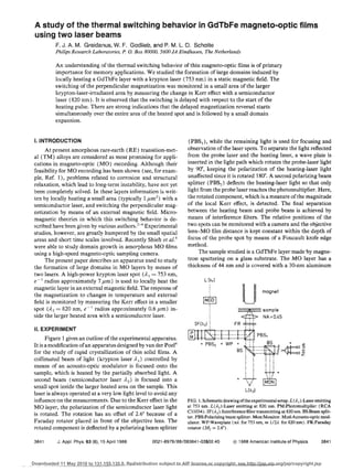
- 1. A study of the thermal switching behavior in GdTbfe magneto ..optic films using two laser beams F. J. A. M. Greidanus, W. F. Godiieb, and P. M. L O. Scholte Philips Research Laboratories, P. 0. Box 80000. 5600 JA Eindhoven, The Netherlands An understanding of the thermal switching behavior of thin magneto-optic films is of primary importance for memory applications. We studied the formation of large domains induced by locally heating a GdTbFe layer with a krypton laser (753 nm) in a static magnetic field. The switching of the perpendicular magnetization was monitored in a small area of the larger krypton-laser-irradiated area by measuring the change in Kerr effect with a semiconductor laser (820 nrn). It is observed that the switching is delayed with respect to the start of the heating pulse. There are strong indications that the delayed magnetization reversal starts simultaneously over the entire area of the heated spot and is followed by a small domain expansion. I. INTRODUCTION (PBS 1 ), while the remaining light is used for focusing and At present amorphous rare-earth (RE) transition-met- observation of the laser spots. To separate the light reflected al (TM) alloys are considered as most promising for appli- from the probe laser and the heating laser, a wave plate is cations in magneto-optic (MO) recording. Although their inserted in the light path which rotates the probe-laser light feasibility for MO recording has been shown (see, for exam- by 90", keeping the polarization of the heating-laser light ple, Ref. 1), problems related to corrosion and structural unaffected since it is rotated 180". A second polarizing beam relaxation, which lead to long-term instability, have not yet splitter (PBSz ) deflects the heating-laser light so that only been completely solved. In these layers information is writ- light from the probe laser reaches the photomultiplier. Here, ten by locally heating a small area (typically 1 ,um2 ) with a the rotated component, which is a measure of the magnitude semiconductor laser, and switching the perpendicular mag- of the local Kerr effect, is detected. The final separation netization by means of an external magnetic field. Micro- between the heating beam and probe beam is achieved by magnetic theories in which this switching behavior is de- means of interference filters. The relative positions of the scribed have been given by various authors. 2-4 Experimental two spots can be monitored with a camera and the objective studies, however, are greatly hampered by the small spatial lens-MO film distance is kept constant within the depth of areas and short time scales involved. Recently Shieh et af.5 focus of the probe spot by means of a Foucault knife edge were able to study domain growth in amorphous MO films method. using a high-speed magneto-optic sampling camera. The sample studied is a GdTbFe layer made by magne- The present paper describes an apparatus used to study tron sputtering on a glass substrate. The MO layer has a the formation of large domains in MO layers by means of thickness of 44 nm and is covered with a 30-nm aluminum two lasers. A high-power krypton laser spot (AI = 753 nm, e--! radius approximately 7/.tm) is used to locally heat the magnetic layer in an external magnetic field. The response of the magnetization to changes in temperature and external field is monitored by measuring the Kerr effect in a smaller 1M9D1 , spot (A 2 = 820 nm, e-! radius approximately 0.6 pm) in- , , ~~~::Zsampe side the larger heated area with a semiconductor laser. , I , NA:::O.45 , IF(r'2l 1 II. EXPERIMENT I Figure 1 gives an outline of the experimental apparatus. It is a modification of an apparatus designed by van der Poe1 6 for the study of rapid crystallization of thin solid films. A collimated beam of light (krypton laser A I) controlled by means of an acousto-optic modulator is focused onto the sample, which is heated by the partially absorbed light. A second beam (semiconductor laser )'2) is focused into a small spot inside the larger heated area on the sample. This laser is always operated at a very low light level to avoid any influence on the measurements. Due to the Kerr effect in the FIG. 1. Schematic drawing ofthe experimental setup. L (,ol. 1) :Laser emitting MO layer, the polarization of the semiconductor laser light at 753 urn. L(22 ):Laser emitting at 820 nm. PM:Photomultiplier (RCA C31034). IF(2 2 } :Interference filter transmitting at 820 urn. BS:Beam split- is rotated. The rotation has an offset of 2.6" because of a ter. PBS:Polarizing beam splitter. Mon:Monitor. Mod:Acousto-optic mod- Faraday rotator placed in front of the objective lens. The ulator. WP:Waveplate (1M. for 753 nrn, m 112,1 for B20nm). FR:Faraday mtated component is deflected by a polarizing beam splitter rotator (28/ = 2.6·). 3641 J. Appl. Phys. 63 (8), 15 April 1988 0021-8979/88/083841-03$02.40 @ 1988 American Institute of Physics 3841 Downloaded 11 May 2010 to 131.155.135.0. Redistribution subject to AIP license or copyright; see http://jap.aip.org/jap/copyright.jsp
- 2. protection/reflection layer. The GdTbFe layer has a perpen- dicular anisotropy and a compensation point below room temperature. sol In Ref. 6 a simple model for the thermal behavior of a H,{kA/m) r ~ thin layer on a substrate subject to a laser pulse is discussed. It is shown that the temperature increase in the center ofthe t 60 heating spot, measured from the beginning of the heating pulse, is given by 40 ~ 1l.T= (aPhTl!2A,po)arctan-J4Dt!p~. Here Po is the e-- 1 radius of the pulsed Gaussian heat source, (1) 20 and A and D are the heat conductivity and coefficient of heat 0 - diffusion of the substrate, respectively. a is the absorbed Q 2 4 6 8 10 12 fraction of the power, P, incident on the film. Only diffusion Ples • r (mW) in the substrate is taken into account. Radial diffusion effects FIG. 3. Coercive field, obtained form the hysteresis loops shown in Fig. 2, as in the metallic layer are neglected. In our experiment the a function oflaser power. The drawn line is a guide to the eye. appropriate values are Po = 7.0 pm, D = 4.8x 10- 7 m 2 /s, )" = 1.10 W ImK, and a = 0.54. Half of the temperature rise is realized ina timet, = p~/4D, which amounts to tj = 2611.S behavior around the coercive field. At a time t, the heating in our case. In about 5t I' which would amount to 130 ftS, the laser is switched on while the Kerr rotation is monitored temperature has risen to about 75% of its final value. By with the probe laser. Due to the heating induced by the ab- monitoring the change of the magnitude of the Kerr effect, sorbed power, the magnitude of the Kerr effect decreases. as measured by the probe beam after the start of a heating After a certain delay time td the Kerr effect changes sign due pulse, it is found that the temperature rise slows down in to a magnetization reversal in the small spot. At a time tf the times of about 100-300 fts. We regard this to be a satisfac- heating power is switched off and the magnitude of the Kerr tory agreement in view of the simple model. effect increases by the same magnitude as at time t j • Surpris- iii. MEASUREMENTS ingly the delay times tei varied strongly as a function of ap- plied field and heating-laser power. Delay times, measured Figure 2 shows a series of hysteresis loops, measured at the same position on the sample as the hysteresis loops of with the setup described. The external magnetic field was Fig. 2, are shown in Fig. 4 as a function of field for various varied slowly while the spot area was kept at an equilibrium powers of the heating laser. Every data point shown is an temperature determined by the power of the heating beam. average of 10 measurements. Under these conditions the de- The Kerr effect was simultaneously measured with the lay times td vary from 200 f:.ts to 2 s. Like the hysteresis probe spot. The squareness of the hysteresis loops indicates a measurements these data also depend somewhat on the posi- perpendicular anisotropy at an temperatureso At the highest laser powers of the heating beam the Curie temperature is approached. In Figo 3 the coercive field obtained from the hysteresis loops in Fig. 2 is shown as a function of heating~ laser power. The rapid decrease at higher temperatures is 8.9mW x clearly observed. The functional dependence, however, proved to be somewhat dependent on the position on the sample, which may be due for instance to compositional var- iations. to (5) 10· .7,"W x In a second set of experiments we studied the switching t 10" lalmW " 10.5ml/l ,." ", OroW ~ ' "~ !<5mW -100 I f 10"2 J ! .1Oll e, ?BmW 96mW r r ~~ o~~ -;00 10.9mW i .100 e, o~ 8.4,"W 10"> ~ -100 I ! .100 e, 8.8"'W ""'0 -1Oe -;00 1 +~oo - .... H [kA/m, --'9' H (kA/m) 0 20 t.O 60 80 --.- H (kA/ml FIG. 2. Kerr rotation as a function of external magnetic field, measured at FIG. 4. Delay times as a function of the external field, measured for various )..2 = 820 urn, for various values of the excitation power (A,= 753 nm). powers of the pump beam. Drawn lines are guides to the eye. 3642 J. Appl. Phys., Vol. 63, No.8, 15 Aprii 1988 Greidanus, Godlieb, and Scholte 3842 Downloaded 11 May 2010 to 131.155.135.0. Redistribution subject to AIP license or copyright; see http://jap.aip.org/jap/copyright.jsp
- 3. From Eq. (1) it is dear that the temperature siowly 0 approaches its equilibrium value. To investigate whether this could be the origin of the delayed switching we did the 10" following: At relatively long times compared to t l • Eq. (1) tc (s) can be approximated and a linear expression for 11P as a function of 1/.Jt is found. The slope of the function is given t by 10" t.(1!P) _ - a/AT (2) b.( I1.J r) - 2AD 1!2ff3/2 . It can be shown 7 that this expression is more generally valid than Eq. (1). By plotting values of 1/P vs 1/.JT as obtained from Fig. 5 and by adopting values of the constants given in Sec. II, we calculate a temperature rise of AT = 93 ± 10K. 8 9 10 11 12 This value is in reasonable agreement with the switching - ..... Plose, (mW) temperature for this measurement estimated form Fig. 3. FIG. 5. Delay times &~ a function of power of the large pump laser beam, for This agreement indicates that an important contribution to a fixed value of the external field. The drawn line is a guide t() the eye. the observed delay times comes from thermal effects: It takes a finite time, which depends on the heating power, to reach the switching temperature. However, other effects may con- tion of the heating spot on the sample. At some positions, tribute as welL When measuring hysteresis curves like much shorter delay times could be obtained. Finally, in Fig. shown in Fig. 2 we observed time-dependent effects, indicat- 5, delay times as a function of heating laser power at a fixed ing that magnetic processes may also be of importance. With value of the external field are shown. respect to delayed switching it may be remarked that similar phenomena have been observed by Verhulst et a1. 8 in photo- IV. DISCUSSiON AND CONCLUSIONS magnetic garnets. They also observed a delayed switching, From the measurements discussed in Sec. III it appears which they characterized with a so-caned breakfree time t hf • that magnetization reversal within the area of the probe spot A possible mechanism may be that after nucleation the do- takes place after a time td , which, under specific conditions main waH moves with a low velocity. After a certain time this (low field, low heating-laser power), may range up to se- velocity becomes unstable and the domain wall moves much conds. However, it cannot be inferred from the data whether faster, immediately leading to the observed magnetization reversal. nucleation starts at an earlier moment in the heated region outside the probe spot. The observed magnetization reversal The effects discussed in this paper are of importance for the understanding of the behavior of RE-TM layers used for would then correspond to a domain waH passing under the MO recording. small laser spot. To investigate this we performed a number of experiments in which the heating beam was switched off ACKNOWLEDGMENTS just before the observation of magnetization reversal with the probe laser was expected to occur. Subsequently the We thank B. A. J. Jacobs and A. H. M. Holtslag for heated area was investigated with a polarization microscope. stimulaiing discussions and are much indebted to U. Enz for No sign of domain nucleation inside the heated area was ever useful suggestions and clarifying remarks. The sample was found. In a second experiment the probe spot was slowly kindly prepared by H. J. R Wilting of Philips and DuPont moved towards the edge of the heated area while the delay Optical Company. time measurements were repeated. No significant changes in delay times were found until the edge was reached. Switch- ing always occurred instantaneously on the time scale of the 'M. Hartmann, J. Braat, and B. Jacobs, IEEE Trans. Magn. MAG·20, 1013 (1984). experiments. When the edge was reached the delay time in· 2B. G. Ruth, IBM J. Res. Develop. HI, IOn (1974). creased and switching no longer occurred instantaneously, 3M. Mansuripur and G. A. N. Connell, J. App!. Phys. 55, 3049 (1984). indicating a domain waH passing slowly through the spot. 4P. Hansell, J. App. Phys. 62, 216 (1987). Although both experiments described above may not be con- 'R·P. D. Shieh and M. H. Kryder. J. App!. Phys. 61,1108 (1987). clusive, they strongly support a picture in which magnetiza- 6c. J. v.d. Poe!, J. Mater. Res. (to be published). 7A. H. M, Holtsiag (privatecommunica!ion). tion reversal starts in an area of the size of the heating-laser "A. G. H. Verhulst, T. Holtwijk, W. Lem~, and U. Enz, IEEE Trans. Magn. spot, fonowed by a small expansion of the domain created. MM"?,729 (1971). 3843 J. Appl. Phys., Vol. 63, No.8, i 5 April 1988 Greidanus, Godlieb, and Scholte 3843 Downloaded 11 May 2010 to 131.155.135.0. Redistribution subject to AIP license or copyright; see http://jap.aip.org/jap/copyright.jsp