
Recomendados
Recomendados
Mais conteúdo relacionado
Destaque
Destaque (17)
Semelhante a The EM network October 2010 Newsletter
Semelhante a The EM network October 2010 Newsletter (20)
Último
Último (20)
The EM network October 2010 Newsletter
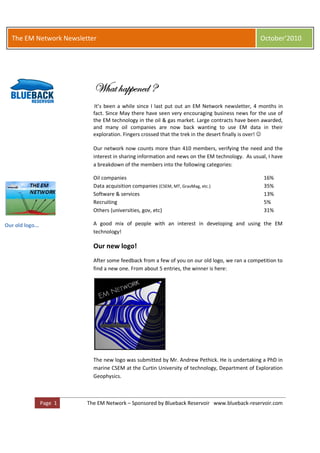
- 1. The EM Network Newsletter October’2010 1 j{tà {tÑÑxÇxw R It’s been a while since I last put out an EM Network newsletter, 4 months in fact. Since May there have seen very encouraging business news for the use of the EM technology in the oil & gas market. Large contracts have been awarded, and many oil companies are now back wanting to use EM data in their exploration. Fingers crossed that the trek in the desert finally is over! ☺ Our network now counts more than 410 members, verifying the need and the interest in sharing information and news on the EM technology. As usual, I have a breakdown of the members into the following categories: Oil companies 16% Data acquisition companies (CSEM, MT, GravMag, etc.) 35% Software & services 13% Recruiting 5% Others (universities, gov, etc) 31% Our old logo... A good mix of people with an interest in developing and using the EM technology! Our new logo! After some feedback from a few of you on our old logo, we ran a competition to find a new one. From about 5 entries, the winner is here: The new logo was submitted by Mr. Andrew Pethick. He is undertaking a PhD in marine CSEM at the Curtin University of technology, Department of Exploration Geophysics. Page 1 The EM Network – Sponsored by Blueback Reservoir www.blueback-reservoir.com
- 2. The EM Network Newsletter October’2010 Comment from Andrew: “I have a feeling that quite a few people have only pictured marine EM as the ray diagram as seen in quite a few places. It is my hope that people understand the behaviour of EM waves as being diffusive (in the case of marine EM) rather than reflective.” Andrew Pethick wins the Blueback iPod for designing the new EM Network logo! Flux lines of electromagnetic fields interacting with a hydrocarbon body. Image courtesy of Andrew Pethick. Call for articles for the next newsletter The next newsletter is scheduled for January’11 and I would like to encourage you to submit articles, reviews, questions, opinions, technology news etc. Your feedback and input is important to make this Newsletter an interesting read! Please also participate in the various discussions on the network web site. We all can learn from reading each other’s views on the EM technology. I appreciate we are all busy but please take a few minutes to do this if you can. Paul Hovdenak (Sponsor and group administrator) paul.hovdenak@blueback-reservoir.com Page 2 The EM Network – Sponsored by Blueback Reservoir www.blueback-reservoir.com
- 3. The EM Network Newsletter October’2010 Table of Contents 1. Member Articles, Reviews, Questions, etc 1.1 Articles Page 4 1.2 Company news Page 7 1.3 Players in the EM market - update Page 9 1.4 Discussion from the web site Page 12 2. Events and technology updates Page 16 3. Career Networking Page 17 4. Request for input to newsletter No6 Page 18 Page 3 The EM Network – Sponsored by Blueback Reservoir www.blueback-reservoir.com
- 4. The EM Network Newsletter October’2010 1. Member Articles, Reviews & Questions 1.1 Articles There are several articles that were candidates for inclusion in this newsletter, but because of copyright laws, and size I decided to instead provide you with some links. The Geophysics magazine from SEG has for the September’10 issue a couple of excellent articles. One by Michael Zhdanov and another one by Steven Constable. Also worth mentioning, is a case study off the coast of Brazil by WesternGeco. See below for the abstracts and where you can find the full articles. Geophysics, Volume 75 Electromagnetic Geophysics: Notes from the past and the road ahead Author: Michael Zhdanov, University of Utah and TechnoImaging Salt Lake City. Abstract: During the last century, electrical geophysics has been transformed from a simple resistivity method to a modern technology that uses complex data- acquisition systems and high-performance computers for enhanced data modeling and interpretation. Not only the methods and equipment have changed but also our ideas about the geo-electrical models used for interpretation have been modified tremendously. This paper describes the evolution of the conceptual and technical foundations of EM methods. It outlines a framework for further development, which should focus on multi- transmitter and multi-receiver surveys, analogous to seismic data-acquisition systems. Important potential topics of future research efforts are in the areas of multidimensional modeling and inversion, including a new approach to the formulation and understanding of EM fields based on flux and voltage representation, which corresponds well to geophysical experiments involving the measurement of voltage and flux of electric and magnetic fields. ©2010 Society of Exploration Geophysicists Page 4 The EM Network – Sponsored by Blueback Reservoir www.blueback-reservoir.com
- 5. The EM Network Newsletter October’2010 Geophysics, Volume 75 Ten years of marine CSEM for hydrocarbon exploration Author: Steven Constable , Scripps Institution of Oceanography, La Jolla California. Abstract: Marine controlled-source electromagnetic (CSEM) surveying has been in commercial use for pre-drill reservoir appraisal and hydrocarbon exploration for 10 years. Although a recent decrease has occurred in the number of surveys and publications associated with this technique, the method has become firmly established as an important geophysical tool in the offshore environment. This is a consequence of two important aspects associated with the physics of the method: First, it is sensitive to high electrical resistivity, which, although not an unambiguous indicator of hydrocarbons, is an important property of economically viable reservoirs. Second, although the method lacks the resolution of seismic wave propagation, it has a much better intrinsic resolution than potential-field methods such as gravity and magnetic surveying, which until now have been the primary non-seismic data sets used in offshore exploration. Although by many measures marine CSEM is still in its infancy, the reliability and noise floors of the instrument systems have improved significantly over the last decade, and interpretation methodology has progressed from simple anomaly detection to 3D anisotropic inversion of multi-component data using some of the world's fastest supercomputers. Research directions presently include tackling the airwave problem in shallow water by applying time-domain methodology, continuous profiling tools, and the use of CSEM for reservoir monitoring during production. ©2010 Society of Exploration Geophysicists The Leading Edge, July’10 issue The Potiguar integrated exploration project: CSEM prospectivity assessment offshore Brazil Authors: Andrea Lovatini, K.Myers, P.Watterson, T.Campbell, WesternGeco Abstract: Newly acquired CSEM data were integrated with several different types of complementary measurements and techniques in an exploration prospect evaluation study—which included petroleum systems modeling (PSM)—of the deepwater offshore area of the Potiguar Basin, northeast Brazil. Page 5 The EM Network – Sponsored by Blueback Reservoir www.blueback-reservoir.com
- 6. The EM Network Newsletter October’2010 Potiguar is the second most productive basin in Brazil, but to date, all production is from its onshore and nearshore areas. A 2D seismic data set was reprocessed then interpreted to provide regional scale horizons, which were used as input, along with other geological and geochemical information, for the study. The CSEM data clearly defined resistive anomalies over five features interpreted as potential traps on the seismic data. The CSEM resistivity volumes have provided added value to the PSM and prospectivity study of this basin. Resistivity modeling with an EM survey layout. Image courtesy of EMGS. Page 6 The EM Network – Sponsored by Blueback Reservoir www.blueback-reservoir.com
- 7. The EM Network Newsletter October’2010 1.2 Company news EMGS updates (from EMGS web site) • July’10 o Contract with Pemex for a multi-year contract worth a minimum of $150 million for 30 deep-water 3D EM surveys. The work programme is in the Mexican sector of the Gulf of Mexico. • September’10 o Contract worth a minimum of $ 3 million in Asia. This contract is a continuation of the previously announced global 3D EM campaign for a major oil company, the first part of which was a survey performed in the Caribbean in the first quarter of 2010. o Woodside has awarded Fugro a controlled-source electromagnetic survey contract on Australia’s North West Shelf in 4Q 2010. Fugro has subcontracted the acquisition portion to EMGS. This $2-million contract will be the first executed under the Fugro/EMGS alliance which was organized in 2009. The agreement gives Fugro full access to EMGS’ marine electromagnetic services. • October’10 “It is only when they o Electromagnetic Geoservices ASA (EMGS) announced go wrong that today that it has secured late-sales worth approximately USD 4 million for its multi-client 3D EM data in the Barents machines remind you Sea, ahead of Norway's 21st exploration licensing round. how powerful they These revenues will be recognised in the third quarter of are” 2010. Industry pre-funding and late-sales year-to-date Clive James totals approximately USD 10 million, of which USD 6 million were recognised in the second quarter of 2010. • Edda consortium o EMGS is pleased to announce that it has received industry funding for a joint project to accelerate the use of 3D EM data in exploration and production. The EDDA project involves acquiring state-of-the-art 3D EM data over known fields on the Norwegian Continental Shelf. Data acquisition over the Linerle and Valkyrie fields has already started using EMGS's mobile acquisition set deployed on the vessel Siem Mollie. The vessel will subsequently acquire data over the Snøhvit field, and it is expected that this survey will be completed by the end of September’10. OHM updates (from OHM web site) • June’10 Page 7 The EM Network – Sponsored by Blueback Reservoir www.blueback-reservoir.com
- 8. The EM Network Newsletter October’2010 o Contract with Bridge Energy UK in the North Sea. The project, under OHM's WISE (Well Integration with Seismic and Electromagnetics) product includes providing the client with a fully integrated dataset, comprising seismic, CSEM and well information. The OHM Express, a state-of-the-art vessel for conducting safe and reliable CSEM operations, will acquire the CSEM survey. • July’10 o Several projects in the Asia-Pacific region performed during the summer, with contract extensions expected. Petromarker updates (from Petromarker web site) • August’10 o PetroMarker AS and Concedo ASA, a Norwegian exploration oil company, have signed a contract for the acquisition of EM data on the Norwegian Continental Shelf (NCS). TEMP-VEL, the proprietary marine vertical EM technology of PetroMarker, will be used to provide Concedo with valuable assessment data. Blueback Reservoir updates Blueback has released another version of the Bridge CSEM visualization and interpretation Petrel plug-in software. The new version includes upgrades to the Bridge interpretation loop for combining EM forward modelling with interpretation of recorded data and EM inversion analysis. Blueback Reservoir and TechnoImaging have entered into a development agreement for adding TechnoImaging technology within EM forward modeling, EM inversion and imaging to the Bridge interpretation workflow. For more information contact Blueback on www.blueback-reservoir.com. Page 8 The EM Network – Sponsored by Blueback Reservoir www.blueback-reservoir.com
- 9. The EM Network Newsletter October’2010 1.3 The players in the EM market This overview of the players in the EM market will be included in future Newsletters – and will be updated based on your feedback and input. I expect this list of companies to grow based your feedback, so please take a moment to look through it and send me your comments. Companies offering survey planning and design, data acquisition, processing and interpretation • OHM o www.Ohmsurveys.com • EMGS o www.emgs.com • Schlumberger WesternGeco. o http://www.westerngeco.com/services/electromagnetics.aspx • Petromarker o www.petromarker.com • PGS o www.pgs.com/Geophysical-services/Electromagnetic-services • EMTEK o www.emtek.as • Multifield Geophysics o www.multifield-geophysics.com • KMS Technologies (owned by EMGS). o www.kmstechnologies.com • Fugro o www.fugro.com • Quantec Geoscience o www.quantecgeoscience.com Companies offering data processing and/or interpretation • Comsol o Software solutions for multiphysics modeling o www.comsol.com • Blueback Reservoir o Software development and consulting services o www.blueback-reservoir.com • OHM-RSI (owned by OHM) Page 9 The EM Network – Sponsored by Blueback Reservoir www.blueback-reservoir.com
- 10. The EM Network Newsletter October’2010 o www.ohmrsi.com • Geosystem (owned by SLB WesternGeco) o www.geosystem.net • TechnoImaging o www.technoimaging.com Industry consortia • SEMC consortium at SCRIPPS o http://marineemlab.ucsd.edu • Marine Control Source ElectroMagnetic Consortium (CSEM) o http://geophysics.mines.edu/cgem/consortia/csem.html • Wise o www.rocksolidimages.com/wise.htm • CEMI at University of Utah o http://cemi-dt-13.gg.utah.edu/~wmcemi/ Academia, research institutes, etc • National Oceanography Centre, UK o www.noc.soton.ac.uk/gg/research/geophysics/em.php • NGI, Norway o www.ngi.no/en/Areas-of-research-and- development/Geophysics • Colorado School of Mines, USA o http://geophysics.mines.edu/cgem/hot_topics/csem_full.ht ml • SCRIPPS Institution of Oceanography, USA o http://marineemlab.ucsd.edu • SINTEF research, Norway o www.sintef.no/Home/Petroleum-and-Energy/SINTEF- Petroleum-Research/Seismic-and-Reservoir- Technology/Seismic/Electromagnetic-modeling • Open EM – a community resource for electromagnetic geophysics o www.openEM.org • EarthScope o www.EMScope.org – the MT component of a large US project managed by Oregon State University • The Electromagnetics Academy o http://emacademy.mit.edu/ Page The EM Network – Sponsored by Blueback Reservoir www.blueback-reservoir.com 10
- 11. The EM Network Newsletter October’2010 • MTNet o A resource for scientists engaged in the study of the Earth using electromagnetic methods, principally the magnetotelluric technique (magnetotellurics). o http://mtnet.dias.ie/main/ As you can see from this temporary list, it only covers the companies involved with the CSEM technology. This is not a limitation so please forward to me links to companies working on the electromagnetic technology for the oil and gas business. Companies providing hardware and EM equipment • Phoenix Geophysics Limited o Land Instruments (receivers and transmitters) for MT - AMT - CSEM - TDEM (Fixed loop, LOTEM) , FDEM, IP, SIP. o Instruments engineered for deep exploration. Sensors adapted for Marine CSEM. Transmitters from 3 to 200 kW (FD and TD) o http://www.phoenix-geophysics.com • Geometrics Scientists have discovered a o Stratagem system (AMT-CSAMT) and their shallow FDEM noise made just prior to the o http://www.geometrics.com Big Bang, which sounds • Metronix o MT receiver equipment something like "Oops" o http://88.198.212.158/mtxweb/index.php Cully Abrell • Zonge o Receivers and Transmitters fro AMT MT (16 bit) CSAMT TEM and SIP o http://www.zonge.com.au • Alpha Geoscience o light TDEM system called Terratem o http://www.alpha-geo.com Page The EM Network – Sponsored by Blueback Reservoir www.blueback-reservoir.com 11
- 12. The EM Network Newsletter October’2010 1.4 Discussion from the web site Our web site has a Discussions page with several interesting discussions lately. Here is an example: Vertical vs Horizontally Oriented Sensor Arrays Chris Walker, RXT Can anyone in the group share with me their experiences of CSEM using the vertical array (Petromarker) method, and compare it to the traditional horizontal array (EMGS/OHM) approach? Kerry Key, Scripps I took a theoretical look at this in a Geophysics paper published last year: E-H streamlines. Image courtesy http://marineemlab.ucsd.edu/~kkey/Pubs/2009b.pdf of Andrew Pethick. In brief, the horizontal transmitter has superior resolution to a vertical transmitter. This was also suggested, but not proven, in the original paper on marine CSEM: Chave, A. and C. Cox, 1982, Controlled electromagnetic sources for measuring electrical-conductivity beneath the oceans. 1. Forward problem and model study: Journal of Geophys- ical Research, 87, no. NB7, 5327–5338 “It was with unalloyed Mårten Blixt, Blueback pleasure that I became aware that a vigorous To add some nuance, PetroMarker has made a comment to your article Kerry: earthquake was in http://petromarker.com/comment-article-geophysics progress” G.K.Gilbert on the 1906 San To be fair, both methods have their pros and cons, but without doubt is the Fransisco earthquake traditional approach more mature and robust. Kerry Key, Scripps Thanks Mårten for pointing that out, hadn't seen that yet. My paper doesn't consider Petromarker's specific Jz-Ez system, rather it was intended to be an apples-to-apples comparison of horizontal versus vertical transmitters, with all other parameters and noise levels being equal. Page The EM Network – Sponsored by Blueback Reservoir www.blueback-reservoir.com 12
- 13. The EM Network Newsletter October’2010 Terje Holten's comments about my paper are interesting and I would love to see them elaborated in a peer-reviewed paper. Certainly both horizontal and vertical transmitter methods benefit in measurement precision (but perhaps not survey cost) when the transmitter is parked on the seafloor for each transmission location. So Petromarker's method does have a precision advantage, but i'm not sure that the increased cost of slowing down the survey acquisition is a fair trade off in the value proposition. And obviously you could park a horizontal transmitter on the seabed and also achieve a higher precision measurement. So apples-to-apples, I still say the resolution is better for a horizontal transmitter. I'd also like to respond to his concern about the 1% relative noise floor I used, which he stated is much larger than what Petromarker's system can achieve. An absolute noise floor of about 0.1 - 1 nV or so is fairly standard for good electric field sensors. Normalize that by a dipole moment of about 100,000 Am and you get around 10^-15 V/Am^2 as the absolute system-noise floor. This is what Holten states in his response, which I agree with as a representative absolute noise floor and hence why I used that in my paper. So what about the relative noise floor? That depends on the uncertainty in parameters such as the sensor orientation, sensor calibrations and most importantly the absolute positions of the source and receivers. For the sake of argument, lets suppose we'd like to have 0.1% relative error, rather than the 1% I used. The relative orientation Image courtesy of Westerngeco angle between transmitter and receiver needs to be known to with 3 degrees to get 0.1% relative error, which could easily be obtained with present day tilt meters, so that isn't much of a practical issue unless the tilts aren't measured. Sensor calibrations can be done accurately in the lab to levels of no worse than 0.1%. Finally lets consider position uncertainty. Suppose the receiver is at 500 m offset, as Holten mentions. At this short an offset, the electric field peaks at around 10^-11 and has a spatial gradient in the radial direction that is about 10^-14 V/Am^2 / m. If the source-receiver position uncertainty was 1 m, the relative error would be 0.1%. If the uncertainty in position offset was 10 m, then the relative error would be about 1%. I don't know any contractors getting 1 m position accuracy between two deep water seafloor instruments with standard USBL systems; 10 m is probably more realistic. So i'd say that at best a 0.1% relative error might be possible for some very very carefully collected data. I could re-run my synthetic inversions with this lower noise floor...okay, just did, here are the results: http://marineemlab.ucsd.edu/kkey/RelativeErrorComp.jpg So bumping down the relative error to 0.1% did improve the resolution of the Jz-Ez inversion, but it is still vastly inferior to the horizontal transmitter and receiver (Jy-Ey) with a 1% relative error. I agree with Holten's statement that time-domain and frequency domain methods have different sensitivities. However, since time-domain responses can Page The EM Network – Sponsored by Blueback Reservoir www.blueback-reservoir.com 13
- 14. The EM Network Newsletter October’2010 be obtained by Fourier transformation of the frequency domain responses, the better resolution of horizontal transmitters and receivers will hold for time domain data as well. Stefan Helwig, Emtek Very interesting discussion. Kerry, in your last reply you pointed out that: "since time-domain responses can be obtained by Fourier transformation of the frequency domain responses, the better resolution of horizontal transmitters and receivers will hold for time domain data as well." There is of course no doubt that time domain fields can be calculated using Fourier transform. In order for your argument to work all the time the sensitivity of the response generated by a horizontal transmitter would need to be better than the one generated by a vertical one for all frequencies. Is that actually true? The situation becomes even more complicated if we look at this in 3D. While the above described condition might be true in 1D there actually might be differences in the sensitivities of both approaches depending on reservoir size Intelligence is the ability to and survey objective. adapt to change For a vertical downhole transmitter part of this is discussed in Sholl & Edwards Stephen Hawking 2007 (Geophysics). They point out that the sensitivity towards the lateral boundary is superior with the vertical borehole transmitter. At the same time they point out that the vertical resolution is poorer which is in agreement with your observations. While the situation with the Petromarker system is not 100% the same I still think that the argument should hold for their system too. Terje Holten, Petromarker Hi, I’d like to join this interesting discussion. This discussion is a good reminder for us to publish more results. My college Eirik Flekkøy will have a poster talk at EAGE in Barcelona where we elaborate more on measurement of noise. For the Petromarker technology to work it is necessary to turn off the transmitter during measurement and therefore work in time domain since the offsets are small. Apart this point, it is possible to do a transformation between the two domains, so the difference in theory is small. I agree with Kerry’s comment about positioning. The main contribution comes from the constant uncertainty from the positioning of lower electrode, which is usually larger than the random noise that originates from the movement of the vessel from the fixed point above the measured position of the lower electrode. Some kind of uncertainties have a large magnitude, for instance errors in measured seawater resistivity, but have minor or no impact in the inversion since it only affects the early times. While tilt effects modifies the slope at late times and have a major impact on the inversion. The noise frequencies of 0.1-1 Hz is the most problematic since stacking is not effective here. Page The EM Network – Sponsored by Blueback Reservoir www.blueback-reservoir.com 14
- 15. The EM Network Newsletter October’2010 So how does this compare to the relative noise in Kerry’s paper? The relative noise originates from the transmitter, as I understand. In our case, most of the uncertainties are systematic and repeatable between each pulse , and a smaller part is random. The horizontal method has errors with more random than systematic contributions. The error in offset has low impact on our inversion since it only affects early times, so basically the tilt of transmitter dominates our ‘relative noise’. All in all, adding realistic noise to the vertical dipole is somewhat complicated. I also pointed about that the averaging produced a bias since only short offsets have a value for our method and offsets up to 20 km are used for averaging in Key’s paper. I would prefer a fixed offset of 1000m for Petromarker method, while the horizontal dipole method can use its best offset (7km?). It is possible to do a rerun with a fixed offset, Kerry? Also, what is spectrum of your relative noise? David Alumbaugh, Schlumberger So just to add my two cents here.... We are presenting papers both in Barcelona as well as the SEG looking at the resolving capabilities of the two acquisition scenarios in 1D and 2D (or 3D) from a theoretical perspective; we will also be publishing a paper in Geophysics( when we get around to finishing it). What we have found from both a pure theoretical perspective (approximate analytic solutions) as well as empirical 1D inversion results is that the close offset vertical-vertical system does not have the resolving capability of the standard CSEM configuration. The theoretical analysis has shown that at close offsets such as used by Petromarker, the layer response is dominated by an 'image like' term. This is similar to DC resistivity and central loop TEM. However, in standard CSEM you make measurements at large offsets where you pick up a 'guided mode'. As it turns out this guided mode has much more sensitivity to the properties of the resistive layer than does the image term. So if you run a 1D inversion for the Petromarker configuration and compare it to results for the standard CSEM configuration, what you find is you get much better resolution of the layer resistivity and thickness for the latter, even if you set the noise level for the Petromarker configuration at 10 times less than the horizontal-horizontal data. However the better resolution scenario breaks down in two cases. The first is if for the horizontal-horizontal when you go to a low enough frequency such that you are approaching DC. In this case the guided mode is not generated and all you are left with is an image like layer response (note that this does away with the concept of going to low frequency as a method for mitigating the air-wave effect). Thus the low frequency CSEM inversion results look similar to those that you get by inverting the close offset transient Jz-Ez data. The second case that was alluded to by Stefan above is when you get into 2D and 3D scenarios. To generate the guided mode requires the target to be of sufficient lateral extent. So if the target is smaller than offset that is required to really detect the guided mode, you again only detect an image-like layer response. And in this case because the standard CSEM method is using larger offsets where as the Page The EM Network – Sponsored by Blueback Reservoir www.blueback-reservoir.com 15
- 16. The EM Network Newsletter October’2010 Petromarker example is at fairly short offsets, the Petromarker anomaly is actually larger for the same target. Plus it appears to have better lateral resolution as you go over the edge of the target. However to make use of this lateral resolving capability would require dense, nearly continuous measurements like you get with the towed horizontal source. As I understand it, this continuous profiling acquisition mode is rather difficult with the current Petromarker configuration due to fact that the source boat has to stop and position each new source position rather than continuously towing. I think what it comes down to is both methods have some advantages and disadvantages, with the 'best' measurement system changing depending on geologic situation that is being investigated..... This discussions continues on the web sites with input from Aramco and Fugro/EMGS. 2. Events and technology updates • SEG 2010 in Denver o http://www.seg.org o EM sessions all 3 days. Check out the program on the web site • SCRIPPS o Will host Marelec 2011 – the world’s foremost conference on marine electromagnetics o http://www.marelec.co.uk • Links to various technical papers on EM (please forward additional links for inclusion on this list): o http://www.westerngeco.com/media/resources/articles/200809_a ogr_mmt_improves_subsalt.pdf o www.emgs.com/research_publications/technical_papers.php o www.ohmsurveys.com/case.php o http://www.westerngeco.com/~/media/Files/WesternGeco/resourc es/papers/2009/2009seg30.ashx Page The EM Network – Sponsored by Blueback Reservoir www.blueback-reservoir.com 16
- 17. The EM Network Newsletter October’2010 Find a job you love and you’ll never work a day in your life” Confucius 3. Career Networking Another of the reasons for instigating The EM Network was to advertise career positions that may be of interest to our members. This will never be the major part of our newsletter as the intention is to keep it as technically focused as much as possible. However I intend to carry on with this section until someone convinces me otherwise. The source for these positions is mainly from 1. Our group’s JOBS section on the web site 2. the company web sites 3. recruiters contacting our group Page The EM Network – Sponsored by Blueback Reservoir www.blueback-reservoir.com 17
- 18. The EM Network Newsletter October’2010 • OHM Surveys - http://www.ohmsurveys.com/careers.php • EMGS - http://www.emgs.com/careers/ • Oil Careers recruiting http://careers.infooil.com/fx/jobs/listings/1.343276/sr.geophysicist.in terpretation.of.gravity.magnetics.electromagnetics.aspx • Working Smart recruiting o http://www.earthworks-jobs.com/oil/ws754.html • Misco jobs recruiting o http://www.miscojobs.com/jobs/L_2/job_451282.htm • Piper Morgan recruiting o http://jobview.monster.com/Sr-Geophysicist-Interpretation- of-Gravity-Magnetics-Electromagnetics-Job-Houston-TX-US- 90231607.aspx Page The EM Network – Sponsored by Blueback Reservoir www.blueback-reservoir.com 18
- 19. The EM Network Newsletter October’2010 4. Requests for input for newsletter #6 After receiving this few EM Network newsletters you should now realize the kind of newsletter we are trying to achieve. If you would like to add an article, or some input for the Technology section, for the next newsletter (scheduled for January 2011), then simply email me the proposed article and I will do my best to include it. Regards, Paul.hovdenak@blueback-reservoir.com Autumn is here! - at least on the northern hemisphere :-) Page The EM Network – Sponsored by Blueback Reservoir www.blueback-reservoir.com 19