

Recomendados
Mais conteúdo relacionado
Mais procurados
Mais procurados (20)
Semelhante a Assignment 7
Semelhante a Assignment 7 (20)
Assignment 7
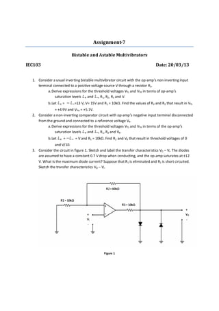
- 1. Assignment-7 Bistable and Astable Multivibrators IEC103 Date: 20/03/13 1. Consider a usual inverting bistable multivibrator circuit with the op-amp’s non-inverting input terminal connected to a positive voltage source V through a resistor R3. a.Derive expressions for the threshold voltages VTL and VTH in terms of op-amp’s saturation levels and , R1, R2, R3 and V. b.Let = =13 V, V= 15V and R1 = 10kΩ. Find the values of R2 and R3 that result in VTL = +4.9V and VTH = +5.1V. 2. Consider a non-inverting comparator circuit with op-amp’s negative input terminal disconnected from the ground and connected to a reference voltage VR. a.Derive expressions for the threshold voltages VTL and VTH in terms of the op-amp’s saturation levels and , R1, R2 and VR. b.Let = = V and R1 = 10kΩ. Find R2 and VR that result in threshold voltages of 0 and V/10. 3. Consider the circuit in figure 1. Sketch and label the transfer characteristics VO – VI. The diodes are assumed to have a constant 0.7 V drop when conducting, and the op-amp saturates at ±12 V. What is the maximum diode current? Suppose that R1 is eliminated and R2 is short circuited. Sketch the transfer characteristics VO – VI. Figure 1
- 2. 4. Consider a bistable circuit having a non-inverting transfer characteristic with = = 12V. VTL = -1V and VTH = +1V. a.For a 0.5 V sine wave (0.5 V is its amplitude) having zero average, what is the output? b.Show the output if a sinusoid of frequency f and amplitude of 1.1 V is applied at the input. By how much can the average of this sinusoidal input shift before the output becomes a constant value. 5. Consider an astable multivibrator circuit shown in figure 2. Find the frequency of oscillation for R1 = 10kΩ, R2 = 16kΩ, R = 62kΩ and C = 10nF. Figure 2 6. Consider the circuit shown in figure 3. Design the circuit to have an output square wave with 5V amplitude and 1kHz frequency using a 10nF capacitor C. Use β = 0.462 and design for a current in the resistive divider approximately equal to the average current in the RC network over ½ cycle. Assuming ±13V op-amp saturation voltages, average that the zener operates at a current of 1mA. Figure 3
- 3. 7. Consider the circuit in figure 4. The circuit consists of an inverting bistable multivibrator, with an output limiter and a non-inverting integrator. Using equal values for all resistors except R7 and a 0.5nF capacitor, design the circuit to obtain a square wave at the output of the bistable multi- vibrator of 15V peak to peak amplitude and 10 kHz frequency. Sketch and label the waveform at the integrator output. Assuming ±13 V op-amp saturation levels, design for a maximum zener current of 1mA. Specify the zener voltage required and give the values of all resistors. Figure 4