SlideShare uma empresa Scribd logo
1 de 18
Baixar para ler offline
AUBTM-23

                                            Bluetooth V2.0 Class 2
                                            module
                                            Product datasheet


General Description
                                            Key Specification
AUBTM-23 is Bluetooth Core V2.0                Fully Qualified Bluetooth v2.0+EDR
compliant module. The module is                system
designed to be embedded in a host              Handsfree/Headset profile, A2DP, AVRCP,
system which requires cable                    OPP support
replacement function. Typically the            Enhanced Audibility and noise
module could interface with a host             cancellation (with additional DSP
through the UART port.                         software)
The module could be used in many               Support UART,USB,PCM,I2C interface to
different application, e.g.:                   host system
     High Quality Stereo Wireless              Integrated battery charger
     Headsets                                  Support for 802.11 Co-existence
      High Quality Mono Headsets               RoHS Compliant
     Hands-Free Car Kits
     Wireless Speakers
     VOIP Handsets
     Analogue and USB Multimedia
     Dongles
     Bluetooth-Enabled Automotive
     Wireless Gateways


                                      Product datasheet                     Page 1 of 18
                                      ©Austar Technology 2009
AUBTM-23


Copyright © 2009-2010 Austar Technology

All rights reserved.

Austar Technology assumes no responsibility for any errors, which may appear in this manual.
Furthermore, Austar Technology reserves the right to alter the hardware, software, and/or specifications
detailed herein at any time without notice, and does not make any commitment to update the information
contained herein. Austar Technologys’ products are not authorized for use as critical components in life
support devices or systems.

The Bluetooth trademark is owned by the Bluetooth SIG Inc., USA, and is licensed to Austar Technology.

All other trademarks listed herein are owned by their respective owners.


                                           Product datasheet                               Page 2 of 18
                                           ©Austar Technology 2009
AUBTM-23

Table of Contents
1   Structure .......................................................................................................................................... 4
2   PCB layout specification................................................................................................................. 4
3   Package Information: ...................................................................................................................... 6
    3.1     Pinout Diagram .............................................................................................................6
    3.2     Terminal Functions .......................................................................................................6
4   Device Terminal Description .......................................................................................................... 8
    4.1     Audio Input/output........................................................................................................8
    4.2     UART ............................................................................................................................8
    4.3     PIO ................................................................................................................................9
    4.4     AIO ...............................................................................................................................9
    4.5     USB...............................................................................................................................9
    4.6     Power control ................................................................................................................9
    4.7     Battery Charger ...........................................................................................................10
5   Electrical specification:................................................................................................................. 11
    5.1     Radio Characteristics ..................................................................................................11
    5.2     Power Control .............................................................................................................11
    5.3     Digital Terminal Input voltage....................................................................................11
    5.4     Digital Terminal Output voltage .................................................................................11
    5.5     Input and Tri-state Current with:.................................................................................11
    5.6     USB Terminals Characteristics ...................................................................................12
    5.7     Auxiliary ADC ............................................................................................................12
    5.8     Audio Input, Microphone Amplifier ...........................................................................12
    5.9     Audio Output, Speaker Output....................................................................................13
6   Manual Soldering.......................................................................................................................... 15
    6.1     Reflow soldering .........................................................................................................15
7   Referenced schematic design ........................................................................................................ 17


                                                            Product datasheet                                                    Page 3 of 18
                                                            ©Austar Technology 2009
AUBTM-23


1 Structure


                            AUSTAR


               21mm


                            AUBTM-23


                                     16mm

                                        32mm

                                                                     2mm


2 PCB layout specification


   No copper in this area            13mm


                        8mm                                    Copper area


                                                            Ground vias


                                  Product datasheet                        Page 4 of 18
                                  ©Austar Technology 2009
AUBTM-23
Figures above illustrates how PCB design around the antenna of AUBTM-23 should be made. The
most important thing is that there is no copper (ground plane or traces) underneath or in the close
proximity of the antenna.

It’s also very important to have grounding vias all the way in the border between ground plane and
free space, as illustrated with black and gray dots in figures above. This prevents the RF signal for
reflecting back to the PCB and signal lines over there.

Try to avoid any metal material near the antenna and keep at least 5mm away if it is inevitable.
A solid ground should be provide for AUBTM-23 and the copper area should be at least 20x15mm
to maintain the best RF performance.


                                                                                  30


                             1


                                          Product datasheet                             Page 5 of 18
                                          ©Austar Technology 2009
AUBTM-23


3 Package Information:

3.1 Pinout Diagram


                          Fig3-1 AUTBTM-21 Pinout


3.2 Terminal Functions

Pin      Pin name   I/O
Number
1.       GND1                Ground
2.       RST                 Reset
3.       AIO1                Analog input/output channel 1
4.       AIO0                Analog input/output channel 0
5.       USB_DN              USB data negative
6.       USB_DP              USB data positive
7.       UART_RTS            UART RTS
8.       UART_CTS            UART CTS
9.       UART_RX             UART RX
10.      UART_TX             UART TX

                               Product datasheet                Page 6 of 18
                               ©Austar Technology 2009
AUBTM-23
11.   PIO10      Digital input/output port 10
12.   PIO9       Digital input/output port 9
13.   PIO11      Digital input/output port 11
14.   PIO15      Digital input/output port 15
15.   PIO7       Digital input/output port 7
16.   PIO13      Digital input/output port 13
17.   PIO12      Digital input/output port 12
18.   PIO4       Digital input/output port 4
19.   PIO5       Digital input/output port 5
20.   PIO6       Digital input/output port 6
21.   PIO14      Digital input/output port 14
22.   PIO8       Digital input/output port 8
23.   PCM_OUT    Synchronous 8 kbps data out (internal Pull down)
24.   PCM_IN     Synchronous 8 kbps data in (internal Pull down)
25.   PCM_SYNC   Synchronous data strobe (internal pull-down)
26.   PCM_CLK    Synchronous data clock (internal pull-down)
27.   PIO2       Digital input/output port
28.   PIO3       Digital input/output port
29.   PIO1       Digital input/output port
30.   PIO0       Digital input/output port
31.   GND2       Ground
32.   SPI_MOSI   SPI data input (pull down)
33.   SPI_CS     Chip selection for SPI (internal pull up, active low)
34.   SPI_CLK    SPI Clock (internal pull down)
35.   SPI_MISO   SPI data output (pull down)
36.   POWER_ON   Power enable
37.   VBAT       Battery in
38.   VCHG       Charging Voltage
39.   MIC_BIAS   Microphone bias
40.   MIC_B_P    Microphone B positive
41.   MIC_B_N    Microphone B negative
42.   MIC_A_P    Microphone A positive
43.   MIC_A_N    Microphone A negative
44.   SPKR_B_P   Speaker B positive
45.   SPKR_B_N   Speaker B negative
46.   SPKR_A_P   Speaker A positive
47.   SPKR_A_N   Speaker A negative


                  Product datasheet                              Page 7 of 18
                  ©Austar Technology 2009
AUBTM-23


4 Device Terminal Description

4.1 Audio Input/output

AUBTM-23 audio input receives its analogue input signal from pins AUDIO_IN_P_LEFT and
AUDIO_IN_N_LEFT. The input can be configured to be either single ended or fully differential.
It can be programmed for either microphone or line input and has a 3-bit digital gain setting of the
input-amplifier in 3dB steps to optimize it for the use of different microphones.

AUBTM-23 has a class-AB amplifier as the audio output-stage and is capable of driving a signal
on both channels of up to 2V pk-pk- differential into a load of 32Ω and 500pF with a typical
THD+N of -74dBc. The output is available as a differential signal between
AUDIO_OUT_N_LEFT and AUDIO_OUT_P_LEFT for the left channel ; and between
AUDIO_OUT_N_RIGHT and AUDIO_OUT_P_RIGHT for the right channel. The output is
capable of driving a speaker directly if its impedance is at least 16Ω if only one channel is
connected or an external regulator is used.


4.2 UART

AUBTM-23 Universal Asynchronous Receiver Transmitter (UART) interface provide s a simple
mechanism for communicating with other serial devices.
 Four signals are used to implement the UART function. When AUBTM-23 is connected to
another digital device, RXD and TXD transfer data between the two devices. The remaining two
signals, NCTS and NRTS, can be used to implement RS232 hardware flow control where both are
active low indicators. All UART connections are implemented using CMOS technology and have
signalling levels of 0V and VDD.

 Parameter                                                         Possible Values
 Baud Rate                                                         1200 Baud (≤2%Error)
                                          Minimum
                                                                   9600 Baud (≤1%Error)
                                          Maximum                  1.5MBaud (≤1%Error)
 Flow Control                                                      RTS/CTS or None
 Parity                                                            None, Odd or Even
 Number of Stop Bits                                               1 or 2
 Bits per channel                                                  8
                                    Possible UART Settings (1)
(1) UART settings are set during factory calibration. Customer should provide desired
                                          Product datasheet                             Page 8 of 18
                                          ©Austar Technology 2009
AUBTM-23
configuration before purchasing.


4.3 PIO

AUBTM-23 provides 16 lines of programmable bi-directional input/outputs (I/O) are provided.
PIO lines can be configured through software to have either weak or strong pull-ups or pull-downs.
All PIO lines are configured as inputs with weak pull-downs at reset.


4.4 AIO

AUBTM-23 has 2 general purpose analogue interface pins, AIO[0], AIO[1] . AIO pins are mainly
used as inputs of internal A/D converters. Typical use of these pins are monitoring the battery
level.


4.5 USB

AUBTM-23 contains a full speed (12Mbits/s) USB interface that is capable of driving a USB
cable directly. No external USB transceiver is required. The device operates as a USB peripheral,
responding to requests from a master host controller such as a PC. Both the OHCI and the UHCI
standards are supported. The set of USB endpoints implemented can behave as specified in the
USB section of the Bluetooth specification v1.2 or alternatively can appear as a set of endpointd
appropriate to USB audio devices such as speakers.
As USB is a Master/Slave oriented system (in common with other USB peripherals), AUBTM-23
only supports USB Slave operation.


4.6 Power control

AUBTM-23 contains built-in DC/DC regulator to provide power supply for the module. A battery
or an external DC power supply could be connected with VBAT to power the module. Pin
Power_on is used to enable the module, allowing the device to boot up. When Power_on is high,
the internal power supply is enabled. The firmware is then about to latch the internal regulator and
the Power_on pin could be released. Power_on has a logic threshold of around 1V, and have weak
pull-downs. It can tolerate voltages up to 4.9V, so it may be connected directly to a battery to
enable the device.


                                          Product datasheet                             Page 9 of 18
                                          ©Austar Technology 2009
AUBTM-23

4.7 Battery Charger

The battery charger is a constant current / constant voltage charger circuit, and is suitable for
lithium ion/polymer batteries only. It shares a connection to the battery terminal, VBAT, with the
switch mode regulator; however it may be used in conjunction with either of the high voltage
regulators on the device. The constant current level can be varied to allow charging of different
capacity batteries. The charger circuit requires configuration and calibration settings which are
stored in the device. To ensure these are set, the circuit enables the active regulators whenever it
enters ‘fast-charge’ mode so that the device will boot-up and run the charger configuration
firmware.
Firmware can detect, using an internal status bit, when the charger is powered.
When the charger supply is not connected to VCHG, the terminal must be left open circuit.


                                           Product datasheet                            Page 10 of 18
                                           ©Austar Technology 2009
AUBTM-23


5 Electrical specification:

5.1 Radio Characteristics

Parameter                                     Min                 Typ               Max                Unit
Output Power                             -                 4                  -                   dBm
Power control range                      14                                                       dB
Power control step                       2                                    8                   dB
Operation Current                                          70                 110                 mA
Sensitivity                                                -80                -82                 dBm


5.2 Power Control

 Parameter                             Min            Typ               Max                     Unit
 Supply Voltage(VBAT)            2.7             -                4.5               V
 Battery Charger Input Voltage   4.5                              6.5               V


5.3 Digital Terminal Input voltage

 Parameter                                           Min            Typ             Max                Unit
 VIL input logic level low                                 -0.4                         +0.8     V
 VIH input logic level high                   2.0625                          3.6                V


5.4 Digital Terminal Output voltage

Parameter                                      Min                Typ               Max                Unit
                                                                              0.125               V
VOL output logic level low

VOL output logic level high              2.475                                3.3V                V


5.5 Input and Tri-state Current with:

Parameter                                     Min                 Typ               Max                   Unit
Strong pull-up                                -100                -40               -10                       μA
Strong pull-down                              +10                 +40               +100                      μA

                                       Product datasheet                                       Page 11 of 18
                                       ©Austar Technology 2009
AUBTM-23
Weak pull-up                                    -5.0          -1.0     -0.2               μA
Weak pull-down                                  +0.2          +1.0     +5.0               μA
I/O pad leakage current                          -1            0        +1                μA
CI Input Capacitance                            1.0            -       5.0                 pF


5.6 USB Terminals Characteristics

Parameter                                        Min           Typ     Max          Unit

VDD_USB for correct USB operation                3.1                    3.6           V


Input threshold

VIL input logic level low                             -            -   0.99           V
VIH input logic level high                       2.31              -     -            V

Input leakage current

VSS < VIN < VDD                                   -1               1    5           μA
CI Input capacitance                             2.5               -   10.0          pF
Output Voltage levels to correctly
terminated USB Cable
VOL output logic level low                       0.0               -    0.2           V
VOH output logic level high                      2.8               -    3.3           V


5.7 Auxiliary ADC

Parameter                                        Min           Typ     Max          Unit
Resolution                                        -                -    8           Bits

Input voltage range (LSB size = 3.3/255)          0                -   3.3           V

Accuracy(Guaranteed                 INL           -1               -    1           LSB
monotonic)                    DNL                 0                -    1           LSB
Offset                                            -1               -    1           LSB
Gain Error                                       -0.8              -   0.8           %
Input Bandwidth                                   -            100      -           kHz
Conversion time                                   -            2.5      -           μs
Sample rate(2)                                    -                -   700       Samples/s


5.8 Audio Input, Microphone Amplifier

Parameter                                        Min           Typ     Max          Unit
Input full scale at maximum gain                  -                4    -         mV rms
Input full scale at minimum gain                  -            400      -         mV rms

                                           Product datasheet                  Page 12 of 18
                                           ©Austar Technology 2009
AUBTM-23
Gain resolution                                    -             3             -                 dB
Distortion at 1kHz                                 -                          -74                dB
Input referenced rms noise                         -             8             -              μV rms
3dB Bandwidth                                      -            17             -                kHz
Input impedance                                    -            20             -                 kΩ
THD+N (microphone input) @ 30mV rms
                                                   -            -66            -                 dB
input
THD+N (line input) @ 300mV Ω input(9)              -            -74            -                 dB


5.9 Audio Output, Speaker Output

Parameter     Symbol    Conditions                     Min            Typ          Max           Unit

Allowed                 Resistive                      16               -          O.C.           Ω
Load                    Capacitive                      -               -          500            pF
Max                     RL=600Ω                         -              2.0           -         V pk-pk
output
voltage
Max                     RL=22Ω                          -              75            -           mA
output
current
Total
Harmonic                fIN=1kHz, BW=22Hz to
              THD+N                                     -             0.015          -            %
Distortion              22kHz RL=600Ω
plus Noise
Output
                        A Weighted, Po=digital
noise
              SNR       silence, RL=600Ω,               -              -91           -            dB
relative to
                        BW=22Hz to 22kHz
full scale
Channel                 fIN=10kHz, analogue
Separation    CS        output set to maximum           -               -           -60           dB
(Crosstalk)             gain
Power         PSRR      Vripple=200mVpk-pk              -             TBD            -            dB
Supply                  sinewave, 10kHz at
Rejection               VREG_IN. 2.3V ≤
Ratio                   VREG_IN ≤ 4.1V,
                        analogue output set to
                        maximum gain
Second
                        1kHz sinewave, 1dB
Harmonic                                                -             <-95           -            dB
                        below full scale 600Ω
Level


                                            Product datasheet                             Page 13 of 18
                                            ©Austar Technology 2009
AUBTM-23
Third
           1kHz sinewave, 1dB
Harmonic                                 -             -95     -           dB
           below full scale 600Ω
Level


                             Product datasheet                     Page 14 of 18
                             ©Austar Technology 2009
AUBTM-23
SOLDERING


6 Manual Soldering
TBA


6.1 Reflow soldering

The soldering profile depends on various parameters necessitating a set up for each
application. The data here is given only for guidance on solder re-flow. There are four
zones:

      1. Preheat Zone - This zone raises the temperature at a controlled rate, typically
         1-2.5°C/s.

      2. Equilibrium Zone - This zone brings the board to a uniform temperature and also
         activates the flux. The duration in this zone (typically 2-3 minutes) will need to be
         adjusted to optimize the out gassing of the flux.

      3. Reflow Zone - The peak temperature should be high enough to achieve good
         wetting but not so high as to cause component discoloration or damage. Excessive
         soldering time can lead to intermetallic growth which can result in a brittle joint.

      4. Cooling Zone - The cooling rate should be fast, to keep the solder grains small which
          will give a longer lasting joint. Typical rates will be 2-5°C/s.

      5. Solder Re-Flow Profile for Devices with Lead-Free Solder Balls

Composition of the solder ball: Sn 95.5%, Ag 4.0%, Cu 0.5%


                                        Product datasheet                        Page 15 of 18
                                        ©Austar Technology 2009
AUBTM-23


                               Figure 34: Reflow solder profile

Key features of the profile:

    • Initial Ramp = 1-2.5°C/sec to 175°C±25°C equilibrium

    • Equilibrium time = 60 to 180 seconds

    • Ramp to Maximum temperature (250°C) = 3°C/sec max.

    • Time above liquidus temperature (217°C): 45-90 seconds

    • Device absolute maximum reflow temperature: 260°C

Devices will withstand the specified profile. Lead-free devices will withstand up to three
reflows to a maximum temperature of 260°C.


                                       Product datasheet                      Page 16 of 18
                                       ©Austar Technology 2009
AUBTM-23


7 Referenced schematic design


                 Product datasheet            Page 17 of 18
                 ©Austar Technology 2009
AUBTM-23
Revision History
 DATE              VERSION   DESCRIPTION
 Jul 04, 2009      a         Preliminary publication


                                    Product datasheet            Page 18 of 18
                                    ©Austar Technology 2009

Mais conteúdo relacionado

Mais procurados

Ericsson RBS 6000 & 3000 & 2000
Ericsson RBS 6000 & 3000 & 2000Ericsson RBS 6000 & 3000 & 2000
Ericsson RBS 6000 & 3000 & 2000ibrahimnabil17
 
Xtrem n p1560t
Xtrem n p1560tXtrem n p1560t
Xtrem n p1560tDevanceiro
 
Huawei DBS 3900 Hardware Structure
Huawei DBS 3900 Hardware StructureHuawei DBS 3900 Hardware Structure
Huawei DBS 3900 Hardware Structureibrahimnabil17
 
3RU AOS03 Catv optical transmission platform
3RU AOS03 Catv optical transmission platform3RU AOS03 Catv optical transmission platform
3RU AOS03 Catv optical transmission platformShanxi Cai
 
MYD-YA15XC-T Development Board
MYD-YA15XC-T Development BoardMYD-YA15XC-T Development Board
MYD-YA15XC-T Development BoardLinda Zhang
 
Hi t 70xx system overview
Hi t 70xx  system overviewHi t 70xx  system overview
Hi t 70xx system overviewThien Huynh
 
Biến tần Frenic ACE - www.haophuong.com
Biến tần Frenic ACE - www.haophuong.comBiến tần Frenic ACE - www.haophuong.com
Biến tần Frenic ACE - www.haophuong.comCTY TNHH HẠO PHƯƠNG
 
Catalog general pa si intercom
Catalog general pa si intercomCatalog general pa si intercom
Catalog general pa si intercomRomAudioVideo
 
Development Board for NXP i.MX 8M Quad Application Processors
Development Board for NXP i.MX 8M Quad Application ProcessorsDevelopment Board for NXP i.MX 8M Quad Application Processors
Development Board for NXP i.MX 8M Quad Application ProcessorsLinda Zhang
 
Processor module Ax-som-cl335x reference
Processor module Ax-som-cl335x referenceProcessor module Ax-som-cl335x reference
Processor module Ax-som-cl335x referenceAlexey Yurko
 
Advanced motion controls mc4xdzp01
Advanced motion controls mc4xdzp01Advanced motion controls mc4xdzp01
Advanced motion controls mc4xdzp01Electromate
 
Nexaira Nexconnect Router User Guide (quantum-wireless.com)
Nexaira Nexconnect Router User Guide (quantum-wireless.com)Nexaira Nexconnect Router User Guide (quantum-wireless.com)
Nexaira Nexconnect Router User Guide (quantum-wireless.com)Ari Zoldan
 
USB Training - Silicon Labs -
USB Training - Silicon Labs -USB Training - Silicon Labs -
USB Training - Silicon Labs -Emanuele Bonanni
 
Myir product catalog
Myir product catalogMyir product catalog
Myir product catalognie, jack
 
Electronics & computing - All connectors
Electronics & computing - All connectorsElectronics & computing - All connectors
Electronics & computing - All connectorsdegarden
 

Mais procurados (19)

Ericsson RBS 6000 & 3000 & 2000
Ericsson RBS 6000 & 3000 & 2000Ericsson RBS 6000 & 3000 & 2000
Ericsson RBS 6000 & 3000 & 2000
 
Xtrem n p1560t
Xtrem n p1560tXtrem n p1560t
Xtrem n p1560t
 
Huawei DBS 3900 Hardware Structure
Huawei DBS 3900 Hardware StructureHuawei DBS 3900 Hardware Structure
Huawei DBS 3900 Hardware Structure
 
SMARC Development Kit
SMARC Development KitSMARC Development Kit
SMARC Development Kit
 
3RU AOS03 Catv optical transmission platform
3RU AOS03 Catv optical transmission platform3RU AOS03 Catv optical transmission platform
3RU AOS03 Catv optical transmission platform
 
MYD-YA15XC-T Development Board
MYD-YA15XC-T Development BoardMYD-YA15XC-T Development Board
MYD-YA15XC-T Development Board
 
Hi t 70xx system overview
Hi t 70xx  system overviewHi t 70xx  system overview
Hi t 70xx system overview
 
Biến tần Frenic ACE - www.haophuong.com
Biến tần Frenic ACE - www.haophuong.comBiến tần Frenic ACE - www.haophuong.com
Biến tần Frenic ACE - www.haophuong.com
 
Catalog general pa si intercom
Catalog general pa si intercomCatalog general pa si intercom
Catalog general pa si intercom
 
Development Board for NXP i.MX 8M Quad Application Processors
Development Board for NXP i.MX 8M Quad Application ProcessorsDevelopment Board for NXP i.MX 8M Quad Application Processors
Development Board for NXP i.MX 8M Quad Application Processors
 
Processor module Ax-som-cl335x reference
Processor module Ax-som-cl335x referenceProcessor module Ax-som-cl335x reference
Processor module Ax-som-cl335x reference
 
Advanced motion controls mc4xdzp01
Advanced motion controls mc4xdzp01Advanced motion controls mc4xdzp01
Advanced motion controls mc4xdzp01
 
Ericsson RBS 6000
Ericsson RBS 6000Ericsson RBS 6000
Ericsson RBS 6000
 
Nexaira Nexconnect Router User Guide (quantum-wireless.com)
Nexaira Nexconnect Router User Guide (quantum-wireless.com)Nexaira Nexconnect Router User Guide (quantum-wireless.com)
Nexaira Nexconnect Router User Guide (quantum-wireless.com)
 
XMC4000 Brochure | Infineon Technologies
XMC4000 Brochure | Infineon TechnologiesXMC4000 Brochure | Infineon Technologies
XMC4000 Brochure | Infineon Technologies
 
USB Training - Silicon Labs -
USB Training - Silicon Labs -USB Training - Silicon Labs -
USB Training - Silicon Labs -
 
Myir product catalog
Myir product catalogMyir product catalog
Myir product catalog
 
USGM705 9
USGM705 9USGM705 9
USGM705 9
 
Electronics & computing - All connectors
Electronics & computing - All connectorsElectronics & computing - All connectors
Electronics & computing - All connectors
 

Semelhante a AUBTM-23 datasheet

A6vmx series users_manual
A6vmx series users_manualA6vmx series users_manual
A6vmx series users_manualluissinato
 
4 Channel Relay Board 5V-Bluetooth Compatible for Arduino
4 Channel Relay Board 5V-Bluetooth Compatible for Arduino4 Channel Relay Board 5V-Bluetooth Compatible for Arduino
4 Channel Relay Board 5V-Bluetooth Compatible for ArduinoRaghav Shetty
 
Bmt 2098 c-a-line_scan_camera_user_manual
Bmt 2098 c-a-line_scan_camera_user_manualBmt 2098 c-a-line_scan_camera_user_manual
Bmt 2098 c-a-line_scan_camera_user_manualBalajimicrotechnologies
 
Bala ji microtechnologies analog line scan camera korea
Bala ji microtechnologies analog line scan camera koreaBala ji microtechnologies analog line scan camera korea
Bala ji microtechnologies analog line scan camera koreabalajibmt02
 
Xb5 r batteryless wireless switch
Xb5 r batteryless wireless switchXb5 r batteryless wireless switch
Xb5 r batteryless wireless switchweihong liu
 
Huawei umts node b configuration principle
Huawei umts node b configuration principleHuawei umts node b configuration principle
Huawei umts node b configuration principleYaser Al-Abdali
 
Huaweiumtsnodebconfigurationprinciple 161222082051
Huaweiumtsnodebconfigurationprinciple 161222082051Huaweiumtsnodebconfigurationprinciple 161222082051
Huaweiumtsnodebconfigurationprinciple 161222082051moussaCoulibaly22
 
Toshiba Cortex Seminar in Israel
Toshiba Cortex Seminar in Israel Toshiba Cortex Seminar in Israel
Toshiba Cortex Seminar in Israel Amir Sherman
 
LM358 dual operational amplifier
LM358 dual operational amplifierLM358 dual operational amplifier
LM358 dual operational amplifierEasonchenng
 
240243228 huawei-bts-3900-training-150914113641-lva1-app6892
240243228 huawei-bts-3900-training-150914113641-lva1-app6892240243228 huawei-bts-3900-training-150914113641-lva1-app6892
240243228 huawei-bts-3900-training-150914113641-lva1-app6892moussaCoulibaly22
 
240243228 huawei-bts-3900-training
240243228 huawei-bts-3900-training240243228 huawei-bts-3900-training
240243228 huawei-bts-3900-trainingShelton Siziba
 
Huawei BTS 3900 Hardware Structure
Huawei BTS 3900 Hardware StructureHuawei BTS 3900 Hardware Structure
Huawei BTS 3900 Hardware Structureibrahimnabil17
 
American Fibertek MRM14852F8 User Manual
American Fibertek MRM14852F8 User ManualAmerican Fibertek MRM14852F8 User Manual
American Fibertek MRM14852F8 User ManualJMAC Supply
 
Manual pc chips_m812_lmr-h_v5,0
Manual pc chips_m812_lmr-h_v5,0Manual pc chips_m812_lmr-h_v5,0
Manual pc chips_m812_lmr-h_v5,0Vitor Albuquerque
 

Semelhante a AUBTM-23 datasheet (20)

A6vmx series users_manual
A6vmx series users_manualA6vmx series users_manual
A6vmx series users_manual
 
Aspire 4551 g
Aspire 4551 gAspire 4551 g
Aspire 4551 g
 
BTS
BTSBTS
BTS
 
4 Channel Relay Board 5V-Bluetooth Compatible for Arduino
4 Channel Relay Board 5V-Bluetooth Compatible for Arduino4 Channel Relay Board 5V-Bluetooth Compatible for Arduino
4 Channel Relay Board 5V-Bluetooth Compatible for Arduino
 
Hc 06
Hc 06Hc 06
Hc 06
 
Bmt 2098 c-a-line_scan_camera_user_manual
Bmt 2098 c-a-line_scan_camera_user_manualBmt 2098 c-a-line_scan_camera_user_manual
Bmt 2098 c-a-line_scan_camera_user_manual
 
Bala ji microtechnologies analog line scan camera korea
Bala ji microtechnologies analog line scan camera koreaBala ji microtechnologies analog line scan camera korea
Bala ji microtechnologies analog line scan camera korea
 
Xb5 r batteryless wireless switch
Xb5 r batteryless wireless switchXb5 r batteryless wireless switch
Xb5 r batteryless wireless switch
 
Jm20329 datasheet
Jm20329 datasheetJm20329 datasheet
Jm20329 datasheet
 
Huawei umts node b configuration principle
Huawei umts node b configuration principleHuawei umts node b configuration principle
Huawei umts node b configuration principle
 
Huaweiumtsnodebconfigurationprinciple 161222082051
Huaweiumtsnodebconfigurationprinciple 161222082051Huaweiumtsnodebconfigurationprinciple 161222082051
Huaweiumtsnodebconfigurationprinciple 161222082051
 
Toshiba Cortex Seminar in Israel
Toshiba Cortex Seminar in Israel Toshiba Cortex Seminar in Israel
Toshiba Cortex Seminar in Israel
 
LM358 dual operational amplifier
LM358 dual operational amplifierLM358 dual operational amplifier
LM358 dual operational amplifier
 
L78MS05
L78MS05L78MS05
L78MS05
 
240243228 huawei-bts-3900-training-150914113641-lva1-app6892
240243228 huawei-bts-3900-training-150914113641-lva1-app6892240243228 huawei-bts-3900-training-150914113641-lva1-app6892
240243228 huawei-bts-3900-training-150914113641-lva1-app6892
 
240243228 huawei-bts-3900-training
240243228 huawei-bts-3900-training240243228 huawei-bts-3900-training
240243228 huawei-bts-3900-training
 
Catálogo de PLC S7-200 SMART
Catálogo de PLC S7-200 SMART Catálogo de PLC S7-200 SMART
Catálogo de PLC S7-200 SMART
 
Huawei BTS 3900 Hardware Structure
Huawei BTS 3900 Hardware StructureHuawei BTS 3900 Hardware Structure
Huawei BTS 3900 Hardware Structure
 
American Fibertek MRM14852F8 User Manual
American Fibertek MRM14852F8 User ManualAmerican Fibertek MRM14852F8 User Manual
American Fibertek MRM14852F8 User Manual
 
Manual pc chips_m812_lmr-h_v5,0
Manual pc chips_m812_lmr-h_v5,0Manual pc chips_m812_lmr-h_v5,0
Manual pc chips_m812_lmr-h_v5,0
 

Último

Navigating the Deluge_ Dubai Floods and the Resilience of Dubai International...
Navigating the Deluge_ Dubai Floods and the Resilience of Dubai International...Navigating the Deluge_ Dubai Floods and the Resilience of Dubai International...
Navigating the Deluge_ Dubai Floods and the Resilience of Dubai International...Orbitshub
 
MINDCTI Revenue Release Quarter One 2024
MINDCTI Revenue Release Quarter One 2024MINDCTI Revenue Release Quarter One 2024
MINDCTI Revenue Release Quarter One 2024MIND CTI
 
Polkadot JAM Slides - Token2049 - By Dr. Gavin Wood
Polkadot JAM Slides - Token2049 - By Dr. Gavin WoodPolkadot JAM Slides - Token2049 - By Dr. Gavin Wood
Polkadot JAM Slides - Token2049 - By Dr. Gavin WoodJuan lago vázquez
 
Artificial Intelligence Chap.5 : Uncertainty
Artificial Intelligence Chap.5 : UncertaintyArtificial Intelligence Chap.5 : Uncertainty
Artificial Intelligence Chap.5 : UncertaintyKhushali Kathiriya
 
Axa Assurance Maroc - Insurer Innovation Award 2024
Axa Assurance Maroc - Insurer Innovation Award 2024Axa Assurance Maroc - Insurer Innovation Award 2024
Axa Assurance Maroc - Insurer Innovation Award 2024The Digital Insurer
 
Architecting Cloud Native Applications
Architecting Cloud Native ApplicationsArchitecting Cloud Native Applications
Architecting Cloud Native ApplicationsWSO2
 
Cloud Frontiers: A Deep Dive into Serverless Spatial Data and FME
Cloud Frontiers:  A Deep Dive into Serverless Spatial Data and FMECloud Frontiers:  A Deep Dive into Serverless Spatial Data and FME
Cloud Frontiers: A Deep Dive into Serverless Spatial Data and FMESafe Software
 
Biography Of Angeliki Cooney | Senior Vice President Life Sciences | Albany, ...
Biography Of Angeliki Cooney | Senior Vice President Life Sciences | Albany, ...Biography Of Angeliki Cooney | Senior Vice President Life Sciences | Albany, ...
Biography Of Angeliki Cooney | Senior Vice President Life Sciences | Albany, ...Angeliki Cooney
 
ProductAnonymous-April2024-WinProductDiscovery-MelissaKlemke
ProductAnonymous-April2024-WinProductDiscovery-MelissaKlemkeProductAnonymous-April2024-WinProductDiscovery-MelissaKlemke
ProductAnonymous-April2024-WinProductDiscovery-MelissaKlemkeProduct Anonymous
 
Apidays New York 2024 - The value of a flexible API Management solution for O...
Apidays New York 2024 - The value of a flexible API Management solution for O...Apidays New York 2024 - The value of a flexible API Management solution for O...
Apidays New York 2024 - The value of a flexible API Management solution for O...apidays
 
Repurposing LNG terminals for Hydrogen Ammonia: Feasibility and Cost Saving
Repurposing LNG terminals for Hydrogen Ammonia: Feasibility and Cost SavingRepurposing LNG terminals for Hydrogen Ammonia: Feasibility and Cost Saving
Repurposing LNG terminals for Hydrogen Ammonia: Feasibility and Cost SavingEdi Saputra
 
Exploring the Future Potential of AI-Enabled Smartphone Processors
Exploring the Future Potential of AI-Enabled Smartphone ProcessorsExploring the Future Potential of AI-Enabled Smartphone Processors
Exploring the Future Potential of AI-Enabled Smartphone Processorsdebabhi2
 
EMPOWERMENT TECHNOLOGY GRADE 11 QUARTER 2 REVIEWER
EMPOWERMENT TECHNOLOGY GRADE 11 QUARTER 2 REVIEWEREMPOWERMENT TECHNOLOGY GRADE 11 QUARTER 2 REVIEWER
EMPOWERMENT TECHNOLOGY GRADE 11 QUARTER 2 REVIEWERMadyBayot
 
AXA XL - Insurer Innovation Award Americas 2024
AXA XL - Insurer Innovation Award Americas 2024AXA XL - Insurer Innovation Award Americas 2024
AXA XL - Insurer Innovation Award Americas 2024The Digital Insurer
 
Apidays New York 2024 - APIs in 2030: The Risk of Technological Sleepwalk by ...
Apidays New York 2024 - APIs in 2030: The Risk of Technological Sleepwalk by ...Apidays New York 2024 - APIs in 2030: The Risk of Technological Sleepwalk by ...
Apidays New York 2024 - APIs in 2030: The Risk of Technological Sleepwalk by ...apidays
 
Rising Above_ Dubai Floods and the Fortitude of Dubai International Airport.pdf
Rising Above_ Dubai Floods and the Fortitude of Dubai International Airport.pdfRising Above_ Dubai Floods and the Fortitude of Dubai International Airport.pdf
Rising Above_ Dubai Floods and the Fortitude of Dubai International Airport.pdfOrbitshub
 
Why Teams call analytics are critical to your entire business
Why Teams call analytics are critical to your entire businessWhy Teams call analytics are critical to your entire business
Why Teams call analytics are critical to your entire businesspanagenda
 
DEV meet-up UiPath Document Understanding May 7 2024 Amsterdam
DEV meet-up UiPath Document Understanding May 7 2024 AmsterdamDEV meet-up UiPath Document Understanding May 7 2024 Amsterdam
DEV meet-up UiPath Document Understanding May 7 2024 AmsterdamUiPathCommunity
 
"I see eyes in my soup": How Delivery Hero implemented the safety system for ...
"I see eyes in my soup": How Delivery Hero implemented the safety system for ..."I see eyes in my soup": How Delivery Hero implemented the safety system for ...
"I see eyes in my soup": How Delivery Hero implemented the safety system for ...Zilliz
 
Emergent Methods: Multi-lingual narrative tracking in the news - real-time ex...
Emergent Methods: Multi-lingual narrative tracking in the news - real-time ex...Emergent Methods: Multi-lingual narrative tracking in the news - real-time ex...
Emergent Methods: Multi-lingual narrative tracking in the news - real-time ex...Zilliz
 

Último (20)

Navigating the Deluge_ Dubai Floods and the Resilience of Dubai International...
Navigating the Deluge_ Dubai Floods and the Resilience of Dubai International...Navigating the Deluge_ Dubai Floods and the Resilience of Dubai International...
Navigating the Deluge_ Dubai Floods and the Resilience of Dubai International...
 
MINDCTI Revenue Release Quarter One 2024
MINDCTI Revenue Release Quarter One 2024MINDCTI Revenue Release Quarter One 2024
MINDCTI Revenue Release Quarter One 2024
 
Polkadot JAM Slides - Token2049 - By Dr. Gavin Wood
Polkadot JAM Slides - Token2049 - By Dr. Gavin WoodPolkadot JAM Slides - Token2049 - By Dr. Gavin Wood
Polkadot JAM Slides - Token2049 - By Dr. Gavin Wood
 
Artificial Intelligence Chap.5 : Uncertainty
Artificial Intelligence Chap.5 : UncertaintyArtificial Intelligence Chap.5 : Uncertainty
Artificial Intelligence Chap.5 : Uncertainty
 
Axa Assurance Maroc - Insurer Innovation Award 2024
Axa Assurance Maroc - Insurer Innovation Award 2024Axa Assurance Maroc - Insurer Innovation Award 2024
Axa Assurance Maroc - Insurer Innovation Award 2024
 
Architecting Cloud Native Applications
Architecting Cloud Native ApplicationsArchitecting Cloud Native Applications
Architecting Cloud Native Applications
 
Cloud Frontiers: A Deep Dive into Serverless Spatial Data and FME
Cloud Frontiers:  A Deep Dive into Serverless Spatial Data and FMECloud Frontiers:  A Deep Dive into Serverless Spatial Data and FME
Cloud Frontiers: A Deep Dive into Serverless Spatial Data and FME
 
Biography Of Angeliki Cooney | Senior Vice President Life Sciences | Albany, ...
Biography Of Angeliki Cooney | Senior Vice President Life Sciences | Albany, ...Biography Of Angeliki Cooney | Senior Vice President Life Sciences | Albany, ...
Biography Of Angeliki Cooney | Senior Vice President Life Sciences | Albany, ...
 
ProductAnonymous-April2024-WinProductDiscovery-MelissaKlemke
ProductAnonymous-April2024-WinProductDiscovery-MelissaKlemkeProductAnonymous-April2024-WinProductDiscovery-MelissaKlemke
ProductAnonymous-April2024-WinProductDiscovery-MelissaKlemke
 
Apidays New York 2024 - The value of a flexible API Management solution for O...
Apidays New York 2024 - The value of a flexible API Management solution for O...Apidays New York 2024 - The value of a flexible API Management solution for O...
Apidays New York 2024 - The value of a flexible API Management solution for O...
 
Repurposing LNG terminals for Hydrogen Ammonia: Feasibility and Cost Saving
Repurposing LNG terminals for Hydrogen Ammonia: Feasibility and Cost SavingRepurposing LNG terminals for Hydrogen Ammonia: Feasibility and Cost Saving
Repurposing LNG terminals for Hydrogen Ammonia: Feasibility and Cost Saving
 
Exploring the Future Potential of AI-Enabled Smartphone Processors
Exploring the Future Potential of AI-Enabled Smartphone ProcessorsExploring the Future Potential of AI-Enabled Smartphone Processors
Exploring the Future Potential of AI-Enabled Smartphone Processors
 
EMPOWERMENT TECHNOLOGY GRADE 11 QUARTER 2 REVIEWER
EMPOWERMENT TECHNOLOGY GRADE 11 QUARTER 2 REVIEWEREMPOWERMENT TECHNOLOGY GRADE 11 QUARTER 2 REVIEWER
EMPOWERMENT TECHNOLOGY GRADE 11 QUARTER 2 REVIEWER
 
AXA XL - Insurer Innovation Award Americas 2024
AXA XL - Insurer Innovation Award Americas 2024AXA XL - Insurer Innovation Award Americas 2024
AXA XL - Insurer Innovation Award Americas 2024
 
Apidays New York 2024 - APIs in 2030: The Risk of Technological Sleepwalk by ...
Apidays New York 2024 - APIs in 2030: The Risk of Technological Sleepwalk by ...Apidays New York 2024 - APIs in 2030: The Risk of Technological Sleepwalk by ...
Apidays New York 2024 - APIs in 2030: The Risk of Technological Sleepwalk by ...
 
Rising Above_ Dubai Floods and the Fortitude of Dubai International Airport.pdf
Rising Above_ Dubai Floods and the Fortitude of Dubai International Airport.pdfRising Above_ Dubai Floods and the Fortitude of Dubai International Airport.pdf
Rising Above_ Dubai Floods and the Fortitude of Dubai International Airport.pdf
 
Why Teams call analytics are critical to your entire business
Why Teams call analytics are critical to your entire businessWhy Teams call analytics are critical to your entire business
Why Teams call analytics are critical to your entire business
 
DEV meet-up UiPath Document Understanding May 7 2024 Amsterdam
DEV meet-up UiPath Document Understanding May 7 2024 AmsterdamDEV meet-up UiPath Document Understanding May 7 2024 Amsterdam
DEV meet-up UiPath Document Understanding May 7 2024 Amsterdam
 
"I see eyes in my soup": How Delivery Hero implemented the safety system for ...
"I see eyes in my soup": How Delivery Hero implemented the safety system for ..."I see eyes in my soup": How Delivery Hero implemented the safety system for ...
"I see eyes in my soup": How Delivery Hero implemented the safety system for ...
 
Emergent Methods: Multi-lingual narrative tracking in the news - real-time ex...
Emergent Methods: Multi-lingual narrative tracking in the news - real-time ex...Emergent Methods: Multi-lingual narrative tracking in the news - real-time ex...
Emergent Methods: Multi-lingual narrative tracking in the news - real-time ex...
 

AUBTM-23 datasheet

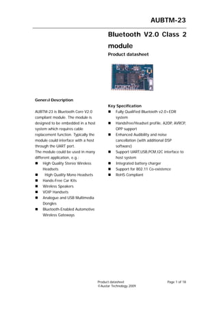
  • 1. AUBTM-23 Bluetooth V2.0 Class 2 module Product datasheet General Description Key Specification AUBTM-23 is Bluetooth Core V2.0 Fully Qualified Bluetooth v2.0+EDR compliant module. The module is system designed to be embedded in a host Handsfree/Headset profile, A2DP, AVRCP, system which requires cable OPP support replacement function. Typically the Enhanced Audibility and noise module could interface with a host cancellation (with additional DSP through the UART port. software) The module could be used in many Support UART,USB,PCM,I2C interface to different application, e.g.: host system High Quality Stereo Wireless Integrated battery charger Headsets Support for 802.11 Co-existence High Quality Mono Headsets RoHS Compliant Hands-Free Car Kits Wireless Speakers VOIP Handsets Analogue and USB Multimedia Dongles Bluetooth-Enabled Automotive Wireless Gateways Product datasheet Page 1 of 18 ©Austar Technology 2009
  • 2. AUBTM-23 Copyright © 2009-2010 Austar Technology All rights reserved. Austar Technology assumes no responsibility for any errors, which may appear in this manual. Furthermore, Austar Technology reserves the right to alter the hardware, software, and/or specifications detailed herein at any time without notice, and does not make any commitment to update the information contained herein. Austar Technologys’ products are not authorized for use as critical components in life support devices or systems. The Bluetooth trademark is owned by the Bluetooth SIG Inc., USA, and is licensed to Austar Technology. All other trademarks listed herein are owned by their respective owners. Product datasheet Page 2 of 18 ©Austar Technology 2009
  • 3. AUBTM-23 Table of Contents 1 Structure .......................................................................................................................................... 4 2 PCB layout specification................................................................................................................. 4 3 Package Information: ...................................................................................................................... 6 3.1 Pinout Diagram .............................................................................................................6 3.2 Terminal Functions .......................................................................................................6 4 Device Terminal Description .......................................................................................................... 8 4.1 Audio Input/output........................................................................................................8 4.2 UART ............................................................................................................................8 4.3 PIO ................................................................................................................................9 4.4 AIO ...............................................................................................................................9 4.5 USB...............................................................................................................................9 4.6 Power control ................................................................................................................9 4.7 Battery Charger ...........................................................................................................10 5 Electrical specification:................................................................................................................. 11 5.1 Radio Characteristics ..................................................................................................11 5.2 Power Control .............................................................................................................11 5.3 Digital Terminal Input voltage....................................................................................11 5.4 Digital Terminal Output voltage .................................................................................11 5.5 Input and Tri-state Current with:.................................................................................11 5.6 USB Terminals Characteristics ...................................................................................12 5.7 Auxiliary ADC ............................................................................................................12 5.8 Audio Input, Microphone Amplifier ...........................................................................12 5.9 Audio Output, Speaker Output....................................................................................13 6 Manual Soldering.......................................................................................................................... 15 6.1 Reflow soldering .........................................................................................................15 7 Referenced schematic design ........................................................................................................ 17 Product datasheet Page 3 of 18 ©Austar Technology 2009
  • 4. AUBTM-23 1 Structure AUSTAR 21mm AUBTM-23 16mm 32mm 2mm 2 PCB layout specification No copper in this area 13mm 8mm Copper area Ground vias Product datasheet Page 4 of 18 ©Austar Technology 2009
  • 5. AUBTM-23 Figures above illustrates how PCB design around the antenna of AUBTM-23 should be made. The most important thing is that there is no copper (ground plane or traces) underneath or in the close proximity of the antenna. It’s also very important to have grounding vias all the way in the border between ground plane and free space, as illustrated with black and gray dots in figures above. This prevents the RF signal for reflecting back to the PCB and signal lines over there. Try to avoid any metal material near the antenna and keep at least 5mm away if it is inevitable. A solid ground should be provide for AUBTM-23 and the copper area should be at least 20x15mm to maintain the best RF performance. 30 1 Product datasheet Page 5 of 18 ©Austar Technology 2009
  • 6. AUBTM-23 3 Package Information: 3.1 Pinout Diagram Fig3-1 AUTBTM-21 Pinout 3.2 Terminal Functions Pin Pin name I/O Number 1. GND1 Ground 2. RST Reset 3. AIO1 Analog input/output channel 1 4. AIO0 Analog input/output channel 0 5. USB_DN USB data negative 6. USB_DP USB data positive 7. UART_RTS UART RTS 8. UART_CTS UART CTS 9. UART_RX UART RX 10. UART_TX UART TX Product datasheet Page 6 of 18 ©Austar Technology 2009
  • 7. AUBTM-23 11. PIO10 Digital input/output port 10 12. PIO9 Digital input/output port 9 13. PIO11 Digital input/output port 11 14. PIO15 Digital input/output port 15 15. PIO7 Digital input/output port 7 16. PIO13 Digital input/output port 13 17. PIO12 Digital input/output port 12 18. PIO4 Digital input/output port 4 19. PIO5 Digital input/output port 5 20. PIO6 Digital input/output port 6 21. PIO14 Digital input/output port 14 22. PIO8 Digital input/output port 8 23. PCM_OUT Synchronous 8 kbps data out (internal Pull down) 24. PCM_IN Synchronous 8 kbps data in (internal Pull down) 25. PCM_SYNC Synchronous data strobe (internal pull-down) 26. PCM_CLK Synchronous data clock (internal pull-down) 27. PIO2 Digital input/output port 28. PIO3 Digital input/output port 29. PIO1 Digital input/output port 30. PIO0 Digital input/output port 31. GND2 Ground 32. SPI_MOSI SPI data input (pull down) 33. SPI_CS Chip selection for SPI (internal pull up, active low) 34. SPI_CLK SPI Clock (internal pull down) 35. SPI_MISO SPI data output (pull down) 36. POWER_ON Power enable 37. VBAT Battery in 38. VCHG Charging Voltage 39. MIC_BIAS Microphone bias 40. MIC_B_P Microphone B positive 41. MIC_B_N Microphone B negative 42. MIC_A_P Microphone A positive 43. MIC_A_N Microphone A negative 44. SPKR_B_P Speaker B positive 45. SPKR_B_N Speaker B negative 46. SPKR_A_P Speaker A positive 47. SPKR_A_N Speaker A negative Product datasheet Page 7 of 18 ©Austar Technology 2009
  • 8. AUBTM-23 4 Device Terminal Description 4.1 Audio Input/output AUBTM-23 audio input receives its analogue input signal from pins AUDIO_IN_P_LEFT and AUDIO_IN_N_LEFT. The input can be configured to be either single ended or fully differential. It can be programmed for either microphone or line input and has a 3-bit digital gain setting of the input-amplifier in 3dB steps to optimize it for the use of different microphones. AUBTM-23 has a class-AB amplifier as the audio output-stage and is capable of driving a signal on both channels of up to 2V pk-pk- differential into a load of 32Ω and 500pF with a typical THD+N of -74dBc. The output is available as a differential signal between AUDIO_OUT_N_LEFT and AUDIO_OUT_P_LEFT for the left channel ; and between AUDIO_OUT_N_RIGHT and AUDIO_OUT_P_RIGHT for the right channel. The output is capable of driving a speaker directly if its impedance is at least 16Ω if only one channel is connected or an external regulator is used. 4.2 UART AUBTM-23 Universal Asynchronous Receiver Transmitter (UART) interface provide s a simple mechanism for communicating with other serial devices. Four signals are used to implement the UART function. When AUBTM-23 is connected to another digital device, RXD and TXD transfer data between the two devices. The remaining two signals, NCTS and NRTS, can be used to implement RS232 hardware flow control where both are active low indicators. All UART connections are implemented using CMOS technology and have signalling levels of 0V and VDD. Parameter Possible Values Baud Rate 1200 Baud (≤2%Error) Minimum 9600 Baud (≤1%Error) Maximum 1.5MBaud (≤1%Error) Flow Control RTS/CTS or None Parity None, Odd or Even Number of Stop Bits 1 or 2 Bits per channel 8 Possible UART Settings (1) (1) UART settings are set during factory calibration. Customer should provide desired Product datasheet Page 8 of 18 ©Austar Technology 2009
  • 9. AUBTM-23 configuration before purchasing. 4.3 PIO AUBTM-23 provides 16 lines of programmable bi-directional input/outputs (I/O) are provided. PIO lines can be configured through software to have either weak or strong pull-ups or pull-downs. All PIO lines are configured as inputs with weak pull-downs at reset. 4.4 AIO AUBTM-23 has 2 general purpose analogue interface pins, AIO[0], AIO[1] . AIO pins are mainly used as inputs of internal A/D converters. Typical use of these pins are monitoring the battery level. 4.5 USB AUBTM-23 contains a full speed (12Mbits/s) USB interface that is capable of driving a USB cable directly. No external USB transceiver is required. The device operates as a USB peripheral, responding to requests from a master host controller such as a PC. Both the OHCI and the UHCI standards are supported. The set of USB endpoints implemented can behave as specified in the USB section of the Bluetooth specification v1.2 or alternatively can appear as a set of endpointd appropriate to USB audio devices such as speakers. As USB is a Master/Slave oriented system (in common with other USB peripherals), AUBTM-23 only supports USB Slave operation. 4.6 Power control AUBTM-23 contains built-in DC/DC regulator to provide power supply for the module. A battery or an external DC power supply could be connected with VBAT to power the module. Pin Power_on is used to enable the module, allowing the device to boot up. When Power_on is high, the internal power supply is enabled. The firmware is then about to latch the internal regulator and the Power_on pin could be released. Power_on has a logic threshold of around 1V, and have weak pull-downs. It can tolerate voltages up to 4.9V, so it may be connected directly to a battery to enable the device. Product datasheet Page 9 of 18 ©Austar Technology 2009
  • 10. AUBTM-23 4.7 Battery Charger The battery charger is a constant current / constant voltage charger circuit, and is suitable for lithium ion/polymer batteries only. It shares a connection to the battery terminal, VBAT, with the switch mode regulator; however it may be used in conjunction with either of the high voltage regulators on the device. The constant current level can be varied to allow charging of different capacity batteries. The charger circuit requires configuration and calibration settings which are stored in the device. To ensure these are set, the circuit enables the active regulators whenever it enters ‘fast-charge’ mode so that the device will boot-up and run the charger configuration firmware. Firmware can detect, using an internal status bit, when the charger is powered. When the charger supply is not connected to VCHG, the terminal must be left open circuit. Product datasheet Page 10 of 18 ©Austar Technology 2009
  • 11. AUBTM-23 5 Electrical specification: 5.1 Radio Characteristics Parameter Min Typ Max Unit Output Power - 4 - dBm Power control range 14 dB Power control step 2 8 dB Operation Current 70 110 mA Sensitivity -80 -82 dBm 5.2 Power Control Parameter Min Typ Max Unit Supply Voltage(VBAT) 2.7 - 4.5 V Battery Charger Input Voltage 4.5 6.5 V 5.3 Digital Terminal Input voltage Parameter Min Typ Max Unit VIL input logic level low -0.4 +0.8 V VIH input logic level high 2.0625 3.6 V 5.4 Digital Terminal Output voltage Parameter Min Typ Max Unit 0.125 V VOL output logic level low VOL output logic level high 2.475 3.3V V 5.5 Input and Tri-state Current with: Parameter Min Typ Max Unit Strong pull-up -100 -40 -10 μA Strong pull-down +10 +40 +100 μA Product datasheet Page 11 of 18 ©Austar Technology 2009
  • 12. AUBTM-23 Weak pull-up -5.0 -1.0 -0.2 μA Weak pull-down +0.2 +1.0 +5.0 μA I/O pad leakage current -1 0 +1 μA CI Input Capacitance 1.0 - 5.0 pF 5.6 USB Terminals Characteristics Parameter Min Typ Max Unit VDD_USB for correct USB operation 3.1 3.6 V Input threshold VIL input logic level low - - 0.99 V VIH input logic level high 2.31 - - V Input leakage current VSS < VIN < VDD -1 1 5 μA CI Input capacitance 2.5 - 10.0 pF Output Voltage levels to correctly terminated USB Cable VOL output logic level low 0.0 - 0.2 V VOH output logic level high 2.8 - 3.3 V 5.7 Auxiliary ADC Parameter Min Typ Max Unit Resolution - - 8 Bits Input voltage range (LSB size = 3.3/255) 0 - 3.3 V Accuracy(Guaranteed INL -1 - 1 LSB monotonic) DNL 0 - 1 LSB Offset -1 - 1 LSB Gain Error -0.8 - 0.8 % Input Bandwidth - 100 - kHz Conversion time - 2.5 - μs Sample rate(2) - - 700 Samples/s 5.8 Audio Input, Microphone Amplifier Parameter Min Typ Max Unit Input full scale at maximum gain - 4 - mV rms Input full scale at minimum gain - 400 - mV rms Product datasheet Page 12 of 18 ©Austar Technology 2009
  • 13. AUBTM-23 Gain resolution - 3 - dB Distortion at 1kHz - -74 dB Input referenced rms noise - 8 - μV rms 3dB Bandwidth - 17 - kHz Input impedance - 20 - kΩ THD+N (microphone input) @ 30mV rms - -66 - dB input THD+N (line input) @ 300mV Ω input(9) - -74 - dB 5.9 Audio Output, Speaker Output Parameter Symbol Conditions Min Typ Max Unit Allowed Resistive 16 - O.C. Ω Load Capacitive - - 500 pF Max RL=600Ω - 2.0 - V pk-pk output voltage Max RL=22Ω - 75 - mA output current Total Harmonic fIN=1kHz, BW=22Hz to THD+N - 0.015 - % Distortion 22kHz RL=600Ω plus Noise Output A Weighted, Po=digital noise SNR silence, RL=600Ω, - -91 - dB relative to BW=22Hz to 22kHz full scale Channel fIN=10kHz, analogue Separation CS output set to maximum - - -60 dB (Crosstalk) gain Power PSRR Vripple=200mVpk-pk - TBD - dB Supply sinewave, 10kHz at Rejection VREG_IN. 2.3V ≤ Ratio VREG_IN ≤ 4.1V, analogue output set to maximum gain Second 1kHz sinewave, 1dB Harmonic - <-95 - dB below full scale 600Ω Level Product datasheet Page 13 of 18 ©Austar Technology 2009
  • 14. AUBTM-23 Third 1kHz sinewave, 1dB Harmonic - -95 - dB below full scale 600Ω Level Product datasheet Page 14 of 18 ©Austar Technology 2009
  • 15. AUBTM-23 SOLDERING 6 Manual Soldering TBA 6.1 Reflow soldering The soldering profile depends on various parameters necessitating a set up for each application. The data here is given only for guidance on solder re-flow. There are four zones: 1. Preheat Zone - This zone raises the temperature at a controlled rate, typically 1-2.5°C/s. 2. Equilibrium Zone - This zone brings the board to a uniform temperature and also activates the flux. The duration in this zone (typically 2-3 minutes) will need to be adjusted to optimize the out gassing of the flux. 3. Reflow Zone - The peak temperature should be high enough to achieve good wetting but not so high as to cause component discoloration or damage. Excessive soldering time can lead to intermetallic growth which can result in a brittle joint. 4. Cooling Zone - The cooling rate should be fast, to keep the solder grains small which will give a longer lasting joint. Typical rates will be 2-5°C/s. 5. Solder Re-Flow Profile for Devices with Lead-Free Solder Balls Composition of the solder ball: Sn 95.5%, Ag 4.0%, Cu 0.5% Product datasheet Page 15 of 18 ©Austar Technology 2009
  • 16. AUBTM-23 Figure 34: Reflow solder profile Key features of the profile: • Initial Ramp = 1-2.5°C/sec to 175°C±25°C equilibrium • Equilibrium time = 60 to 180 seconds • Ramp to Maximum temperature (250°C) = 3°C/sec max. • Time above liquidus temperature (217°C): 45-90 seconds • Device absolute maximum reflow temperature: 260°C Devices will withstand the specified profile. Lead-free devices will withstand up to three reflows to a maximum temperature of 260°C. Product datasheet Page 16 of 18 ©Austar Technology 2009
  • 17. AUBTM-23 7 Referenced schematic design Product datasheet Page 17 of 18 ©Austar Technology 2009
  • 18. AUBTM-23 Revision History DATE VERSION DESCRIPTION Jul 04, 2009 a Preliminary publication Product datasheet Page 18 of 18 ©Austar Technology 2009