SlideShare uma empresa Scribd logo
1 de 20
Baixar para ler offline
Drives 101
                              Lesson 2
                  Control Arrangements for an AFD


          1) Local Control
            Local control means displaying and controlling the
                   system through the keypad on the AFD.


       This training covers the major control arrangements for an AFD. The
control arrangement shown in the previous lesson (Lesson 1: Functions of
an AFD) were all Local Control. There can be other arrangements such as
Remote control, Multi-motor, Master/Slave, Closed Loop, PLC signals and
Serial communications, which are shown in this lesson. This lesson covers
the simplest arrangement first then moves to the more complex.


1.    Local Control
       In the picture above, an AFD, motor and conveyor are operated from
the keypad on the front of the drive. Local control of the AFD means that
operation of the AFD is completed strictly through the keypad on the front of
the drive, or Local Control Panel (LCP). An operator monitors the readings
and controls the AFD by using this keypad. Even if the keypad, LCP is
remotely mounted away from the drive, maximum of 3m (10’), the control
arrangement inside the program of the AFD is still considered as LOCAL.
Anytime LOCAL is seen in the program, please think KEYPAD.
1) Local Control


            Start key starts the drive
            Stop/Reset key stops the drive and also resets the
              drives after an alarm.
            FWD/REV changes direction
            Jog is a pushbutton that runs at a low frequency,
              say at 10Hz, usually used during setup.


       In the picture above there are 2 AFDs, each being controlled by its
own LCP or keypad. The one on the right uses a remote keypad kit to place
the keypad in a convenient location. The operational site on both AFDs is
considered as LOCAL. Anytime the word Local is used in the programming,
example: Parameter 002 (Quick Menu 12 of 13), it means the local keypad
operates the drive.
        The bottom keys on the keypad can be used to start, change direction
FWD/REV (Forward/Reverse), jog, stop and reset the drive. The Jog key
acts like a push button which sends a slow (10Hz) signal to the motor usually
used during setup. When the drive is in Local the drive only responds to the
keypad; all other commands coming to the drive are ignored.
2) Remote Control


        Remote signals are wired into the control section of the
          AFD. They come in 4 types:
             Digital Inputs, Analog Inputs,
             Analog Outputs, Digital/Relay Outputs.


2.    Remote Control
         Other arrangements are possible including remote signals. If there is
a problem and the conveyor must be stopped immediately, it would be
difficult to run back to the AFD to stop it. Stop switches can be placed at key
positions to stop the AFD, AC motor and conveyor. It is important that the
AFD accept these stop signals as well as other remote signals. These
remote control signals come in Four Types:
1) Digital Inputs (DI) are 2-position (ON/OFF) signals sent into the AFD.
These commands tell the AFD to Start/Stop, go Forward/Reverse, Jog or No
Jog, etc. A DI requires 24Vdc which is supplied by a terminal on the drive.
2) Analog Inputs (AI) are proportional or modulating signals sent into the
AFD. These commands tell the AFD what the reference speed should be or
tell the AFD what a feedback signal is doing such as pressure.
3) Analog Outputs (AO) are modulating signals sent by the AFD to a device
such as a meter which could display speed or current.
4) Digital/Relay Outputs (DO/RO) are 2-position (ON/OFF) signals sent by
the AFD to a device such as a light to indicate an Alarm, or when the AFD
has reached a certain speed or to a relay to remove the mechanical brake.
Digital Outputs have power 24Vdc already attached and Relay Outputs do
not have power also known as “dry” contacts.
2) Remote Control


        In the picture above, 2 normally-closed push-button stop
           switches have been wired to 2 Digital Input (DI)
           connections of the control section of the AFD. Notice
           that 24Vdc coming from the AFD is also connected to
           the switches.


       Besides stop switches, other signals can be sent into the AFD. These
could be a reference pot to change the speed, increase and decrease
buttons which would also change the speed, remote Start and Stop switches,
a Jog switch or other signals. All the different options for remote signals are
considered as control wiring. In the program of the drive, if anything other
than the keypad is used to control the drive the operational site, Parameter
002 (Quick Menu 12 of 13), is considered as REMOTE. On the AFD shown
above, all the control wiring terminals are shown on the black plastic cover
just under the keypad (LCP).
       The amount of connections for the control wiring is a means of
comparison between manufacturers of AFDs. As an example, the Danfoss
drive shown above has the ability to accept the following signals:
8 – Digital Inputs (2 inputs can accept pulsed signals from an encoder)
3 – Analog Inputs (2 are setup for 0-10Vdc; 1 for 0-20mA)
2 – Analog/Digital Outputs (0-20mA or 4-20mA signals or these can be
programmed as Digital Outputs with 24Vdc attached)
2 – Relay Outputs (dry contacts)
3) Multi-Motor Operation


          One AFD is used to operate 3 separate AC motors.
            The AFD must be able to handle the maximum
            current for the 3 motors. Some features of the AFD
            in this arrangement are restricted.


3.    Multi-Motor Operation
       The multi-motor arrangement is usually done because of strict cost
considerations. Not only must the AFD have the current capacity for all the
motors, but each individual motor must have overload protection. In the
picture above, one AFD operates 3 AC motors, which in turn operates the 3
conveyors together. They operate at the same speed or close to the same
speed.
        When this arrangement is used some AFD features are restricted.
First the motors and conveyors must all run at the same speed. Another
restriction is that the AFD can not be tuned to a individual motor. Motor
Tuning is where the AFD is tuned or matched to an individual motor for
better performance and energy saving. The last restriction given here is that
the slip compensation should be set in the OFF position.
3) Multi-Motor Operation


         In the example above each of the 3 AC motors is the
            same size and has a maximum current rating, Full
            Load Amps (FLA) of 5 amps. The AFD must be
            sized for 15 amps. Note individual overload
            protection on each motor.


       If the conveyors were operating with a very light load but motor 3 got
jammed, the amp draw on motors 1 and 2, might be low say 2 amps each,
but the draw on motor 3 would need to surpass 11 amps before the drive
saw any problem. As shown in this example, individual overload protection,
such as thermal overloads are needed to protect each motor. Motors in this
arrangement operate close to the same speed.
4) Master/Slave (Leader/Follower)


          In the Master/Slave arrangement a Master or Lead
             AFD is used to operate a single motor and send its
             corresponding signal to the other 2 following motors.
             Features of the AFD which were restricted in the
             multi-motor can be used in this arrangement.


4.    Master/Slave (Leader/Follower)
       This arrangement allows motors to operate closer together than the
multi- motor application. One AFD can be selected as a Master or Leader
drive. It is setup to send a reference signal and ON/OFF commands to the
Slave or Follower drives. In this arrangement the special features of the
drive can be used such as automatic motor tuning and slip compensation.
This arrangement is used when the motors are generally operating at the
same speed with a variance between the drives of 0.3Hz or more.
       Different gear ratios (say 2 to 1) can also be programmed
electronically so that when one drive is at 30Hz the other drive is at 15Hz.
The Master/Slave arrangement is not used where precision of the conveyors
and their speeds must be exact.
4) Master/Slave (Leader/Follower)


           Motor 1, the Master/Leader, sends a reference using
             a 4-20mA signal from its AO to the AI of motor 2. It
             is also possible to send a pulsed signal as a
             reference.


       In the picture above, motor 1 is the master and it sends a reference
signal using one of its analog outputs (AO). Slave/Follower 1, motor 2, then
monitors this 4-20mA signal from the master using its analog input (AI). This
same arrangement is copied between motors 2 and 3. The greatest variance
between drives is around 0.3Hz along the entire range of frequencies, say
from 2 to 60Hz when using the analog 4-20mA signal.
        It is possible with Danfoss drives to use a Digital Output (DO) as the
reference simulating a pulsed output similar to the signal coming from an
encoder. The follower uses a Digital Input (DI) to follow this pulsed
reference signal. The greatest variance between drives using the pulsed
signal is around 0.2Hz along the entire range of frequencies (2 to 60Hz).
There is an additional time delay in this arrangement. The master drive
starts going to its reference before it sends the signal to the slave drives.
Usually this delay is very small, in milliseconds, but it can have a very
harmful effect on certain exact processes. This delay is referred to as a
“propagation delay”.
5) Closed Loop/PID Control


             In this arrangement, a master speed command is
                sent as a reference to each AFD. An encoder at
                each motor verifies the speed. This is referred to
                as Closed Loop, because the AFD has a direct
                feedback from the motor.


5. Closed Loop/PID Control for Speed Regulation
        Up to this point all the previous control arrangements have been open
loop, which means that there is no feedback going directly to the AFD. Closed
Loop is used for more accurate control. In the example above, each drive is
monitoring and controlling at a certain rpm (revolutions per minute), which may
vary from say 100 to 1800rpm (1500rpm for 50Hz motors) Danfoss drives have
the ability to accept a signal from an encoder (one for speed, A; the other for
direction, B) into the AFD without any additional cards or modules.
       In all closed loop applications, additional parameters must be
programmed. These include a speed reference (setpoint), and PID settings. In
this application, the AFD is constantly comparing the reference or setpoint with
the actual feedback value coming from the encoder. If 900 rpm must be
maintained, the encoder should send enough pulses to match it. There is
always a difference between the reference, 900rpm and the actual speed say
893rpm, 7rpm to be exact. This is referred to as Offset, “off the setpoint” or
error.
       PID settings attempt to reduce this error. “P” stands for Proportional
Gain which can be considered as a multiplier of the error. The higher the gain
the more accurate, but the control can be unstable, jittery. “I” stands for Integral
which looks at the error over a certain amount of time. The lower the number
the more frequently it checks the error. If the I setting is too low, the motor
again appears to be jittery. “D” stands for derivative which, if used,
compensates for momentary changes in the load.
5) Closed Loop/PID Control


           In the picture above, the master speed control is sent
              through ratio control pots. Each AFD has its own
              ratio pot to trim the master reference signal, either
              being at full speed or a fixed ration of the master
              speed.


       The application above is an example of how conveyors are used
to mix product together in a certain ratio. In a frozen food plant when
packages of mixed vegetables are put together, there is a certain ratio of
carrots, of green beans, of corn, etc. Each ratio control pot can be
placed so that carrots run at 1000rpm, green beans at 600rpm and corn
at 1200rpm. Even though this arrangement is still used, most factories
use PLCs which are covered later in this section.
       The arrangement without the feedback, known as Open loop is
accurate to 0.5% of actual speed. At 30Hz, 900rpm, open loop is within
+ or – 4.5rpm. With feedback from the encoder, using Closed loop the
accuracy is 0.1% of actual speed. At 30Hz, 900rpm, closed loop is within
+ or – 0.9rpm. For the best precision, a separate card called the Sync-
Pos card is installed inside the drive. Not only does it have as good if not
better accuracy than the closed loop, it also gathers additional
information from the encoder to correct the speed if it lags behind. The
Sync-Pos is covered next.
       Before going on to the Sync-Pos arrangement, another example
of closed loop must be mentioned. Besides Speed Closed Loop, there
can also be Process Closed Loop. Instead of an encoder sending a
feedback signal to the drive, another feedback device such as a 4-20mA
pressure transmitter sends a signal back to the drive. As with any closed
loop application, this application requires proper feedback setup, a
setpoint, controller action and PID settings.
6) Multi-motor with Sync-Pos card


          For precise applications where the drives must be
            timed perfectly together, less than 0.1Hz. This
            arrangement requires the use of encoders.


6.     Multi-motor operation using Sync-Pos Card
         On other applications it is important that AFDs and motors work
preciously together. In the example above there is a master or leader AFD
and slave or follower AFDs. The special Sync-Pos
(Synchronizing/Positioning) card is placed in all 3 drives. This card fits on the
back of the control card so that no additional space is required. The master
Sync-Pos card sends a virtual master signal to all 3 drives. All drives follow
this signal even the master at precisely the same time. Each drive uses an
encoder on the motor to insure that position is maintained exactly. Although
in the example above, matching motors is not essential; there are
applications where timing between processes, such as a bottling line, are
critical.
6) Multi-motor with Sync-Pos card


        Here the master drive sends a virtual signal to all drives.
          Encoders [example:4096 ppr (pulses per one
          revolution)] on each motor check for accuracy, which
          can be within 1/2 of a pulse between drives.


       The synchronization example has been used here, but the Sync-Pos
Card has other functions. It can be used to enter a special program for
positioning. Perhaps the motor needs to run 10 turns forward then waits 5
seconds and returns 10 turns, waits 30 seconds then starts the process all
over again. The Sync-Pos card has programmable capabilities to operate an
AFD in such a manner. A computer or laptop with the proper software is
used to enter this type of program into the Sync-Pos card.
       Danfoss has preprogrammed different applications into the Sync-Pos
card, one for Synchronization and the other for Positioning. These “canned”
applications add a new parameter group into the drive, which allows the
programmer to enter information through the keypad of the drive without a
computer or laptop. Anytime an application is “canned” there are restrictions
on inputs, outputs as well as some programming features.
7) PLC Signals


          Programmed Logic Controllers (PLC) coordinate the
            use of the AFD with numerous other schedules and
            commands. This can be used in very sophisticated
            control arrangements.


7.    PLC signals
        On numerous applications an electronic controller known as
Programmable Logic Controller or PLC is used to add other sensing devices,
scheduling and other coordinated signals. Danfoss does not make PLCs but
it is important that the AFD has the capability to interact with these devices.
The PLC sends a start/stop command (digital output) and the reference
(analog output) to directly control an AFD. These different types of
connections can be referred to as “points”.
      It is also important that the AFD send information back to the PLC,
such as an alarm using a digital/relay output. Using an analog output from
the AFD a true indication of the speed might also be sent back to the PLC.
7) PLC Signals


        Start/Stop command from a DO of the PLC goes to a DI
          of the AFD. A Reference command from an AO of
          the PLC goes to an AI of the AFD.


       An example of a PLC is shown above. Connection wires are run from
the PLC to terminals in the AFD to start/stop and give a reference point.
Other wires can be run from the outputs of the AFD back to PLC to indicate
the status of the drive. With each request for a command or status
information, additional wire connections must be used. Obviously there is an
added expense with each set of wires.
8) Serial Communications


          Serial Communications is accomplished by the wiring
            of 2 wires between each device, which is also
            known as an RS-485 connection. All the +
            terminals are attached together and all the – are
            attached together.


8.    Serial Communications
       With complex PLC applications there can be numerous wires,
perhaps 5 to 10 pairs of wire, between a PLC and the AFD. To reduce this
group of wires the industry is embracing the idea of serial communications
between PLCs and other devices including the AFDs. This allows the
sharing of all sorts of signals including frequency, power, voltage,
temperature, warnings and alarms with the use of an RS-485 (2-wire, + -)
connection.
8) Serial Communications


            In the example shown, the PLC controls (start/stop
               direction change, reference speed, etc) the AFD
               using the RS-485 connection. The AFD also
               sends back status information to the PLC.


       But with serial communications there are some challenges. Different
manufacturers of PLCs communicate in different computer languages.
Siemens which is very popular in Europe communicates using a language
called Profibus. North America uses a great deal of Allen Bradley which
communicates with DeviceNet. These 2 languages do NOT communicate
with each other directly. There are more than just 2 languages, as there are
more than a few PLC manufacturers. A separate communication card must
be installed into the AFD to communicate with each different language.
       Presently, Danfoss has a number of different types of serial
communications cards that slide into the AFD. There is a DeviceNet card
used with Allen Bradley PLCs, Profibus used with Siemens PLCs, Modbus
Plus used with Modicon PLCs/ Square D, an Echelon Lonworks card, which
is used mainly in building automation, HVAC (Heating Ventilating and Air-
Conditioning) and an Interbus card, which is used in the automotive industry.
9) Control Combinations


           It is very possible to have combinations of different
               control arrangements, such as pictured here where
               a PLC, using serial communications, sends signals
               to 3 AFDs that have Sync-Pos cards.


9.    Combinations
        There can be any number of combinations. Perhaps an operator
wants to flip a switch and shift between Local and Remote control, or shift
between serial communications and remote. In the Danfoss drive there are
4 different setups which allow for this shifting between control arrangements
if needed.
Summary

         1) Local Control

         2) Remote Control

         3) Multi-motor Control


Summary
Local         Parameter 002 (Quick Menu 12 0f 13) = Local
              Start/Stop commands are made at the keypad
              Local Reference changes are made at keypad-
              Parameter 003 (Quick Menu 13 of 13)


Remote        Parameter 002 (Quick Menu 12 0f 13) = Remote
              Digital Inputs give Start/Stop commands
              Analog Input - Pot changes speed – reference
              A Drive always needs a Start command and a reference
              other than 0 to operate.


Multi-motor   FLA of all motors = Amps of Drive
              Individual protection for each motor
              Do not use AMA (Motor Tuning)
              Do not use Slip comp
Summary

       4) Master/Slave


       5) Closed Loop/PID


       6) Sync-Pos


Summary
Master/Slave Leader/Follower
              AO of Master goes to AI of Slave (4-20mA)
              DO of Master goes to DI of Slave (Pulse)
              Synchronization – close but not precise


Closed Loop   Feedback using an encoder for speed
              PID (Proportional Gain, Integral, Derivative)


Sync-Pos      Precise synchronization is critical
              Sync-Pos Card generates Virtual master
              Encoder required monitoring each motor
              A special Sync-Pos card is available just for
              Synchronizing and another special card just for
              Positioning. The original Sync-Pos card can be
              programmed for either of these or many more
              applications.
Summary

        7) PLC Signals


        8) PLC Serial Communications


        9) Combinations


Summary
PLC Signals   Digital Outputs from PLC to Digital Input on AFD
              Analog Outputs from PLC to Analog Inputs on AFD
              “Points” are connections to PLC
              AFD Status uses AO and DO back to PLC


PLC Serial    RS-485 (2 wire, + and -) connection
              DeviceNet – Allen Bradley
              Profibus – Siemens
              Modbus Plus – Modicon Square D
              Lonworks – Echelon -HVAC
              Interbus - Automotive


Combinations Numerous combinations of control arrangements are
             possible

Mais conteúdo relacionado

Mais procurados

Sensor de pressão de pneu
Sensor de pressão de pneuSensor de pressão de pneu
Sensor de pressão de pneuCarlos Vergara
 
Catalog Biến tần Frenic5000 vg7s 405c Fuji​-Beeteco.com
Catalog Biến tần Frenic5000 vg7s 405c Fuji​-Beeteco.comCatalog Biến tần Frenic5000 vg7s 405c Fuji​-Beeteco.com
Catalog Biến tần Frenic5000 vg7s 405c Fuji​-Beeteco.comBeeteco
 
Mitsubishi ac servos melservo jn-dienhathe.vn
Mitsubishi ac servos melservo jn-dienhathe.vnMitsubishi ac servos melservo jn-dienhathe.vn
Mitsubishi ac servos melservo jn-dienhathe.vnDien Ha The
 
Mitsubishi inverter freqrol-e700 series dienhathe.vn
Mitsubishi inverter freqrol-e700 series dienhathe.vnMitsubishi inverter freqrol-e700 series dienhathe.vn
Mitsubishi inverter freqrol-e700 series dienhathe.vnDien Ha The
 
Linmot overzicht servo_controller_serie_e1100_duits_4_mb
Linmot overzicht servo_controller_serie_e1100_duits_4_mbLinmot overzicht servo_controller_serie_e1100_duits_4_mb
Linmot overzicht servo_controller_serie_e1100_duits_4_mbmahdi nasiri
 
Catalog Frenic micro - www.haophuong.com
Catalog Frenic micro - www.haophuong.comCatalog Frenic micro - www.haophuong.com
Catalog Frenic micro - www.haophuong.comCTY TNHH HẠO PHƯƠNG
 
Catalog Frenic mini(NEW) -www.haophuong.com
Catalog Frenic mini(NEW) -www.haophuong.comCatalog Frenic mini(NEW) -www.haophuong.com
Catalog Frenic mini(NEW) -www.haophuong.comCTY TNHH HẠO PHƯƠNG
 
LM26484 Power Management Unit
LM26484 Power Management Unit LM26484 Power Management Unit
LM26484 Power Management Unit Premier Farnell
 

Mais procurados (14)

Bien tan-mini
Bien tan-miniBien tan-mini
Bien tan-mini
 
Sensor de pressão de pneu
Sensor de pressão de pneuSensor de pressão de pneu
Sensor de pressão de pneu
 
Frenic5000 vg7s 405c
Frenic5000 vg7s 405cFrenic5000 vg7s 405c
Frenic5000 vg7s 405c
 
Catalog Biến tần Frenic5000 vg7s 405c Fuji​-Beeteco.com
Catalog Biến tần Frenic5000 vg7s 405c Fuji​-Beeteco.comCatalog Biến tần Frenic5000 vg7s 405c Fuji​-Beeteco.com
Catalog Biến tần Frenic5000 vg7s 405c Fuji​-Beeteco.com
 
Mitsubishi ac servos melservo jn-dienhathe.vn
Mitsubishi ac servos melservo jn-dienhathe.vnMitsubishi ac servos melservo jn-dienhathe.vn
Mitsubishi ac servos melservo jn-dienhathe.vn
 
Mitsubishi inverter freqrol-e700 series dienhathe.vn
Mitsubishi inverter freqrol-e700 series dienhathe.vnMitsubishi inverter freqrol-e700 series dienhathe.vn
Mitsubishi inverter freqrol-e700 series dienhathe.vn
 
Linmot overzicht servo_controller_serie_e1100_duits_4_mb
Linmot overzicht servo_controller_serie_e1100_duits_4_mbLinmot overzicht servo_controller_serie_e1100_duits_4_mb
Linmot overzicht servo_controller_serie_e1100_duits_4_mb
 
Lec 12 (cont plc)
Lec 12 (cont plc)Lec 12 (cont plc)
Lec 12 (cont plc)
 
Omron cp1 h
Omron cp1 h Omron cp1 h
Omron cp1 h
 
Catalog Frenic micro - www.haophuong.com
Catalog Frenic micro - www.haophuong.comCatalog Frenic micro - www.haophuong.com
Catalog Frenic micro - www.haophuong.com
 
Exj 8 p
Exj 8 pExj 8 p
Exj 8 p
 
Catalog Frenic mini(NEW) -www.haophuong.com
Catalog Frenic mini(NEW) -www.haophuong.comCatalog Frenic mini(NEW) -www.haophuong.com
Catalog Frenic mini(NEW) -www.haophuong.com
 
Catalog lift hpc
Catalog lift hpcCatalog lift hpc
Catalog lift hpc
 
LM26484 Power Management Unit
LM26484 Power Management Unit LM26484 Power Management Unit
LM26484 Power Management Unit
 

Semelhante a Afd Control

Cataloge ge 3.control and_automation-21_vat300_e_c6-6-4_2_rev_a
Cataloge ge 3.control and_automation-21_vat300_e_c6-6-4_2_rev_aCataloge ge 3.control and_automation-21_vat300_e_c6-6-4_2_rev_a
Cataloge ge 3.control and_automation-21_vat300_e_c6-6-4_2_rev_aDien Ha The
 
ACCELEROMETER BASED GESTURE ROBO CAR
ACCELEROMETER BASED GESTURE ROBO CARACCELEROMETER BASED GESTURE ROBO CAR
ACCELEROMETER BASED GESTURE ROBO CARHarshit Jain
 
Chapter 53
Chapter 53Chapter 53
Chapter 53mcfalltj
 
Electronic Line Break Protector for Fluid Systems
Electronic Line Break Protector for Fluid SystemsElectronic Line Break Protector for Fluid Systems
Electronic Line Break Protector for Fluid SystemsCTi Controltech
 
JVL AC Servo Controllers
JVL AC Servo ControllersJVL AC Servo Controllers
JVL AC Servo ControllersElectromate
 
Catalog Biến tần Frenic ACE Mini (Fuji Electric) - Beeteco.com
Catalog Biến tần Frenic ACE Mini (Fuji Electric) - Beeteco.comCatalog Biến tần Frenic ACE Mini (Fuji Electric) - Beeteco.com
Catalog Biến tần Frenic ACE Mini (Fuji Electric) - Beeteco.comBeeteco
 
Ls catalog thiet bi tu dong i e5_e_1105
Ls catalog thiet bi tu dong i e5_e_1105Ls catalog thiet bi tu dong i e5_e_1105
Ls catalog thiet bi tu dong i e5_e_1105Dien Ha The
 
MICROPROCESSOR AND INTERFACING
MICROPROCESSOR AND INTERFACING MICROPROCESSOR AND INTERFACING
MICROPROCESSOR AND INTERFACING Radhika Talaviya
 
Black Box for a Car
Black Box for a CarBlack Box for a Car
Black Box for a Carsubrat manna
 
Temp based fan speed control
Temp based fan speed controlTemp based fan speed control
Temp based fan speed controlSai Malleswar
 
Interfacing with Atmega 16
Interfacing with Atmega 16Interfacing with Atmega 16
Interfacing with Atmega 16Ramadan Ramadan
 
Ls catalog thiet bi tu dong i s5_e_1105_dienhathe.vn
Ls catalog thiet bi tu dong i s5_e_1105_dienhathe.vnLs catalog thiet bi tu dong i s5_e_1105_dienhathe.vn
Ls catalog thiet bi tu dong i s5_e_1105_dienhathe.vnDien Ha The
 
Cataloge ge 3.control and_automation-20_vat300_e_c6-6-4_1_rev_b
Cataloge ge 3.control and_automation-20_vat300_e_c6-6-4_1_rev_bCataloge ge 3.control and_automation-20_vat300_e_c6-6-4_1_rev_b
Cataloge ge 3.control and_automation-20_vat300_e_c6-6-4_1_rev_bDien Ha The
 
Nanocom defender puma 2.4 + 2.2 manual
Nanocom defender puma 2.4 + 2.2 manualNanocom defender puma 2.4 + 2.2 manual
Nanocom defender puma 2.4 + 2.2 manualEagleBrothersByn
 

Semelhante a Afd Control (20)

Ch12
Ch12Ch12
Ch12
 
Cataloge ge 3.control and_automation-21_vat300_e_c6-6-4_2_rev_a
Cataloge ge 3.control and_automation-21_vat300_e_c6-6-4_2_rev_aCataloge ge 3.control and_automation-21_vat300_e_c6-6-4_2_rev_a
Cataloge ge 3.control and_automation-21_vat300_e_c6-6-4_2_rev_a
 
bus system.pptx
bus system.pptxbus system.pptx
bus system.pptx
 
ACCELEROMETER BASED GESTURE ROBO CAR
ACCELEROMETER BASED GESTURE ROBO CARACCELEROMETER BASED GESTURE ROBO CAR
ACCELEROMETER BASED GESTURE ROBO CAR
 
Chapter 53
Chapter 53Chapter 53
Chapter 53
 
BLD-AC1000S.pdf
BLD-AC1000S.pdfBLD-AC1000S.pdf
BLD-AC1000S.pdf
 
SURVEILLANCE ROBOT
SURVEILLANCE ROBOTSURVEILLANCE ROBOT
SURVEILLANCE ROBOT
 
Electronic Line Break Protector for Fluid Systems
Electronic Line Break Protector for Fluid SystemsElectronic Line Break Protector for Fluid Systems
Electronic Line Break Protector for Fluid Systems
 
JVL AC Servo Controllers
JVL AC Servo ControllersJVL AC Servo Controllers
JVL AC Servo Controllers
 
Catalog Biến tần Frenic ACE Mini (Fuji Electric) - Beeteco.com
Catalog Biến tần Frenic ACE Mini (Fuji Electric) - Beeteco.comCatalog Biến tần Frenic ACE Mini (Fuji Electric) - Beeteco.com
Catalog Biến tần Frenic ACE Mini (Fuji Electric) - Beeteco.com
 
Fadal Spindle Drive and Motor Manual
Fadal Spindle Drive and Motor ManualFadal Spindle Drive and Motor Manual
Fadal Spindle Drive and Motor Manual
 
Ls catalog thiet bi tu dong i e5_e_1105
Ls catalog thiet bi tu dong i e5_e_1105Ls catalog thiet bi tu dong i e5_e_1105
Ls catalog thiet bi tu dong i e5_e_1105
 
MICROPROCESSOR AND INTERFACING
MICROPROCESSOR AND INTERFACING MICROPROCESSOR AND INTERFACING
MICROPROCESSOR AND INTERFACING
 
Black Box for a Car
Black Box for a CarBlack Box for a Car
Black Box for a Car
 
Fadal Diagnostics Maintenance Manual
Fadal Diagnostics Maintenance ManualFadal Diagnostics Maintenance Manual
Fadal Diagnostics Maintenance Manual
 
Temp based fan speed control
Temp based fan speed controlTemp based fan speed control
Temp based fan speed control
 
Interfacing with Atmega 16
Interfacing with Atmega 16Interfacing with Atmega 16
Interfacing with Atmega 16
 
Ls catalog thiet bi tu dong i s5_e_1105_dienhathe.vn
Ls catalog thiet bi tu dong i s5_e_1105_dienhathe.vnLs catalog thiet bi tu dong i s5_e_1105_dienhathe.vn
Ls catalog thiet bi tu dong i s5_e_1105_dienhathe.vn
 
Cataloge ge 3.control and_automation-20_vat300_e_c6-6-4_1_rev_b
Cataloge ge 3.control and_automation-20_vat300_e_c6-6-4_1_rev_bCataloge ge 3.control and_automation-20_vat300_e_c6-6-4_1_rev_b
Cataloge ge 3.control and_automation-20_vat300_e_c6-6-4_1_rev_b
 
Nanocom defender puma 2.4 + 2.2 manual
Nanocom defender puma 2.4 + 2.2 manualNanocom defender puma 2.4 + 2.2 manual
Nanocom defender puma 2.4 + 2.2 manual
 

Último

Call Us 📲8800102216📞 Call Girls In DLF City Gurgaon
Call Us 📲8800102216📞 Call Girls In DLF City GurgaonCall Us 📲8800102216📞 Call Girls In DLF City Gurgaon
Call Us 📲8800102216📞 Call Girls In DLF City Gurgaoncallgirls2057
 
8447779800, Low rate Call girls in Rohini Delhi NCR
8447779800, Low rate Call girls in Rohini Delhi NCR8447779800, Low rate Call girls in Rohini Delhi NCR
8447779800, Low rate Call girls in Rohini Delhi NCRashishs7044
 
Marketplace and Quality Assurance Presentation - Vincent Chirchir
Marketplace and Quality Assurance Presentation - Vincent ChirchirMarketplace and Quality Assurance Presentation - Vincent Chirchir
Marketplace and Quality Assurance Presentation - Vincent Chirchirictsugar
 
PSCC - Capability Statement Presentation
PSCC - Capability Statement PresentationPSCC - Capability Statement Presentation
PSCC - Capability Statement PresentationAnamaria Contreras
 
IoT Insurance Observatory: summary 2024
IoT Insurance Observatory:  summary 2024IoT Insurance Observatory:  summary 2024
IoT Insurance Observatory: summary 2024Matteo Carbone
 
APRIL2024_UKRAINE_xml_0000000000000 .pdf
APRIL2024_UKRAINE_xml_0000000000000 .pdfAPRIL2024_UKRAINE_xml_0000000000000 .pdf
APRIL2024_UKRAINE_xml_0000000000000 .pdfRbc Rbcua
 
Investment in The Coconut Industry by Nancy Cheruiyot
Investment in The Coconut Industry by Nancy CheruiyotInvestment in The Coconut Industry by Nancy Cheruiyot
Investment in The Coconut Industry by Nancy Cheruiyotictsugar
 
(Best) ENJOY Call Girls in Faridabad Ex | 8377087607
(Best) ENJOY Call Girls in Faridabad Ex | 8377087607(Best) ENJOY Call Girls in Faridabad Ex | 8377087607
(Best) ENJOY Call Girls in Faridabad Ex | 8377087607dollysharma2066
 
Annual General Meeting Presentation Slides
Annual General Meeting Presentation SlidesAnnual General Meeting Presentation Slides
Annual General Meeting Presentation SlidesKeppelCorporation
 
Digital Transformation in the PLM domain - distrib.pdf
Digital Transformation in the PLM domain - distrib.pdfDigital Transformation in the PLM domain - distrib.pdf
Digital Transformation in the PLM domain - distrib.pdfJos Voskuil
 
Ms Motilal Padampat Sugar Mills vs. State of Uttar Pradesh & Ors. - A Milesto...
Ms Motilal Padampat Sugar Mills vs. State of Uttar Pradesh & Ors. - A Milesto...Ms Motilal Padampat Sugar Mills vs. State of Uttar Pradesh & Ors. - A Milesto...
Ms Motilal Padampat Sugar Mills vs. State of Uttar Pradesh & Ors. - A Milesto...ShrutiBose4
 
MAHA Global and IPR: Do Actions Speak Louder Than Words?
MAHA Global and IPR: Do Actions Speak Louder Than Words?MAHA Global and IPR: Do Actions Speak Louder Than Words?
MAHA Global and IPR: Do Actions Speak Louder Than Words?Olivia Kresic
 
NewBase 19 April 2024 Energy News issue - 1717 by Khaled Al Awadi.pdf
NewBase  19 April  2024  Energy News issue - 1717 by Khaled Al Awadi.pdfNewBase  19 April  2024  Energy News issue - 1717 by Khaled Al Awadi.pdf
NewBase 19 April 2024 Energy News issue - 1717 by Khaled Al Awadi.pdfKhaled Al Awadi
 
8447779800, Low rate Call girls in Tughlakabad Delhi NCR
8447779800, Low rate Call girls in Tughlakabad Delhi NCR8447779800, Low rate Call girls in Tughlakabad Delhi NCR
8447779800, Low rate Call girls in Tughlakabad Delhi NCRashishs7044
 
8447779800, Low rate Call girls in New Ashok Nagar Delhi NCR
8447779800, Low rate Call girls in New Ashok Nagar Delhi NCR8447779800, Low rate Call girls in New Ashok Nagar Delhi NCR
8447779800, Low rate Call girls in New Ashok Nagar Delhi NCRashishs7044
 
Islamabad Escorts | Call 03070433345 | Escort Service in Islamabad
Islamabad Escorts | Call 03070433345 | Escort Service in IslamabadIslamabad Escorts | Call 03070433345 | Escort Service in Islamabad
Islamabad Escorts | Call 03070433345 | Escort Service in IslamabadAyesha Khan
 
Independent Call Girls Andheri Nightlaila 9967584737
Independent Call Girls Andheri Nightlaila 9967584737Independent Call Girls Andheri Nightlaila 9967584737
Independent Call Girls Andheri Nightlaila 9967584737Riya Pathan
 
8447779800, Low rate Call girls in Shivaji Enclave Delhi NCR
8447779800, Low rate Call girls in Shivaji Enclave Delhi NCR8447779800, Low rate Call girls in Shivaji Enclave Delhi NCR
8447779800, Low rate Call girls in Shivaji Enclave Delhi NCRashishs7044
 

Último (20)

Call Us 📲8800102216📞 Call Girls In DLF City Gurgaon
Call Us 📲8800102216📞 Call Girls In DLF City GurgaonCall Us 📲8800102216📞 Call Girls In DLF City Gurgaon
Call Us 📲8800102216📞 Call Girls In DLF City Gurgaon
 
8447779800, Low rate Call girls in Rohini Delhi NCR
8447779800, Low rate Call girls in Rohini Delhi NCR8447779800, Low rate Call girls in Rohini Delhi NCR
8447779800, Low rate Call girls in Rohini Delhi NCR
 
Marketplace and Quality Assurance Presentation - Vincent Chirchir
Marketplace and Quality Assurance Presentation - Vincent ChirchirMarketplace and Quality Assurance Presentation - Vincent Chirchir
Marketplace and Quality Assurance Presentation - Vincent Chirchir
 
PSCC - Capability Statement Presentation
PSCC - Capability Statement PresentationPSCC - Capability Statement Presentation
PSCC - Capability Statement Presentation
 
IoT Insurance Observatory: summary 2024
IoT Insurance Observatory:  summary 2024IoT Insurance Observatory:  summary 2024
IoT Insurance Observatory: summary 2024
 
APRIL2024_UKRAINE_xml_0000000000000 .pdf
APRIL2024_UKRAINE_xml_0000000000000 .pdfAPRIL2024_UKRAINE_xml_0000000000000 .pdf
APRIL2024_UKRAINE_xml_0000000000000 .pdf
 
Investment in The Coconut Industry by Nancy Cheruiyot
Investment in The Coconut Industry by Nancy CheruiyotInvestment in The Coconut Industry by Nancy Cheruiyot
Investment in The Coconut Industry by Nancy Cheruiyot
 
(Best) ENJOY Call Girls in Faridabad Ex | 8377087607
(Best) ENJOY Call Girls in Faridabad Ex | 8377087607(Best) ENJOY Call Girls in Faridabad Ex | 8377087607
(Best) ENJOY Call Girls in Faridabad Ex | 8377087607
 
Annual General Meeting Presentation Slides
Annual General Meeting Presentation SlidesAnnual General Meeting Presentation Slides
Annual General Meeting Presentation Slides
 
Digital Transformation in the PLM domain - distrib.pdf
Digital Transformation in the PLM domain - distrib.pdfDigital Transformation in the PLM domain - distrib.pdf
Digital Transformation in the PLM domain - distrib.pdf
 
Ms Motilal Padampat Sugar Mills vs. State of Uttar Pradesh & Ors. - A Milesto...
Ms Motilal Padampat Sugar Mills vs. State of Uttar Pradesh & Ors. - A Milesto...Ms Motilal Padampat Sugar Mills vs. State of Uttar Pradesh & Ors. - A Milesto...
Ms Motilal Padampat Sugar Mills vs. State of Uttar Pradesh & Ors. - A Milesto...
 
MAHA Global and IPR: Do Actions Speak Louder Than Words?
MAHA Global and IPR: Do Actions Speak Louder Than Words?MAHA Global and IPR: Do Actions Speak Louder Than Words?
MAHA Global and IPR: Do Actions Speak Louder Than Words?
 
NewBase 19 April 2024 Energy News issue - 1717 by Khaled Al Awadi.pdf
NewBase  19 April  2024  Energy News issue - 1717 by Khaled Al Awadi.pdfNewBase  19 April  2024  Energy News issue - 1717 by Khaled Al Awadi.pdf
NewBase 19 April 2024 Energy News issue - 1717 by Khaled Al Awadi.pdf
 
8447779800, Low rate Call girls in Tughlakabad Delhi NCR
8447779800, Low rate Call girls in Tughlakabad Delhi NCR8447779800, Low rate Call girls in Tughlakabad Delhi NCR
8447779800, Low rate Call girls in Tughlakabad Delhi NCR
 
8447779800, Low rate Call girls in New Ashok Nagar Delhi NCR
8447779800, Low rate Call girls in New Ashok Nagar Delhi NCR8447779800, Low rate Call girls in New Ashok Nagar Delhi NCR
8447779800, Low rate Call girls in New Ashok Nagar Delhi NCR
 
Corporate Profile 47Billion Information Technology
Corporate Profile 47Billion Information TechnologyCorporate Profile 47Billion Information Technology
Corporate Profile 47Billion Information Technology
 
Islamabad Escorts | Call 03070433345 | Escort Service in Islamabad
Islamabad Escorts | Call 03070433345 | Escort Service in IslamabadIslamabad Escorts | Call 03070433345 | Escort Service in Islamabad
Islamabad Escorts | Call 03070433345 | Escort Service in Islamabad
 
No-1 Call Girls In Goa 93193 VIP 73153 Escort service In North Goa Panaji, Ca...
No-1 Call Girls In Goa 93193 VIP 73153 Escort service In North Goa Panaji, Ca...No-1 Call Girls In Goa 93193 VIP 73153 Escort service In North Goa Panaji, Ca...
No-1 Call Girls In Goa 93193 VIP 73153 Escort service In North Goa Panaji, Ca...
 
Independent Call Girls Andheri Nightlaila 9967584737
Independent Call Girls Andheri Nightlaila 9967584737Independent Call Girls Andheri Nightlaila 9967584737
Independent Call Girls Andheri Nightlaila 9967584737
 
8447779800, Low rate Call girls in Shivaji Enclave Delhi NCR
8447779800, Low rate Call girls in Shivaji Enclave Delhi NCR8447779800, Low rate Call girls in Shivaji Enclave Delhi NCR
8447779800, Low rate Call girls in Shivaji Enclave Delhi NCR
 

Afd Control

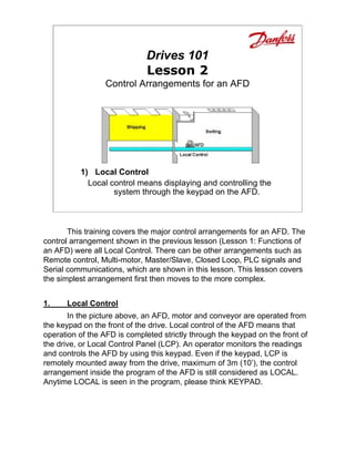
  • 1. Drives 101 Lesson 2 Control Arrangements for an AFD 1) Local Control Local control means displaying and controlling the system through the keypad on the AFD. This training covers the major control arrangements for an AFD. The control arrangement shown in the previous lesson (Lesson 1: Functions of an AFD) were all Local Control. There can be other arrangements such as Remote control, Multi-motor, Master/Slave, Closed Loop, PLC signals and Serial communications, which are shown in this lesson. This lesson covers the simplest arrangement first then moves to the more complex. 1. Local Control In the picture above, an AFD, motor and conveyor are operated from the keypad on the front of the drive. Local control of the AFD means that operation of the AFD is completed strictly through the keypad on the front of the drive, or Local Control Panel (LCP). An operator monitors the readings and controls the AFD by using this keypad. Even if the keypad, LCP is remotely mounted away from the drive, maximum of 3m (10’), the control arrangement inside the program of the AFD is still considered as LOCAL. Anytime LOCAL is seen in the program, please think KEYPAD.
  • 2. 1) Local Control Start key starts the drive Stop/Reset key stops the drive and also resets the drives after an alarm. FWD/REV changes direction Jog is a pushbutton that runs at a low frequency, say at 10Hz, usually used during setup. In the picture above there are 2 AFDs, each being controlled by its own LCP or keypad. The one on the right uses a remote keypad kit to place the keypad in a convenient location. The operational site on both AFDs is considered as LOCAL. Anytime the word Local is used in the programming, example: Parameter 002 (Quick Menu 12 of 13), it means the local keypad operates the drive. The bottom keys on the keypad can be used to start, change direction FWD/REV (Forward/Reverse), jog, stop and reset the drive. The Jog key acts like a push button which sends a slow (10Hz) signal to the motor usually used during setup. When the drive is in Local the drive only responds to the keypad; all other commands coming to the drive are ignored.
  • 3. 2) Remote Control Remote signals are wired into the control section of the AFD. They come in 4 types: Digital Inputs, Analog Inputs, Analog Outputs, Digital/Relay Outputs. 2. Remote Control Other arrangements are possible including remote signals. If there is a problem and the conveyor must be stopped immediately, it would be difficult to run back to the AFD to stop it. Stop switches can be placed at key positions to stop the AFD, AC motor and conveyor. It is important that the AFD accept these stop signals as well as other remote signals. These remote control signals come in Four Types: 1) Digital Inputs (DI) are 2-position (ON/OFF) signals sent into the AFD. These commands tell the AFD to Start/Stop, go Forward/Reverse, Jog or No Jog, etc. A DI requires 24Vdc which is supplied by a terminal on the drive. 2) Analog Inputs (AI) are proportional or modulating signals sent into the AFD. These commands tell the AFD what the reference speed should be or tell the AFD what a feedback signal is doing such as pressure. 3) Analog Outputs (AO) are modulating signals sent by the AFD to a device such as a meter which could display speed or current. 4) Digital/Relay Outputs (DO/RO) are 2-position (ON/OFF) signals sent by the AFD to a device such as a light to indicate an Alarm, or when the AFD has reached a certain speed or to a relay to remove the mechanical brake. Digital Outputs have power 24Vdc already attached and Relay Outputs do not have power also known as “dry” contacts.
  • 4. 2) Remote Control In the picture above, 2 normally-closed push-button stop switches have been wired to 2 Digital Input (DI) connections of the control section of the AFD. Notice that 24Vdc coming from the AFD is also connected to the switches. Besides stop switches, other signals can be sent into the AFD. These could be a reference pot to change the speed, increase and decrease buttons which would also change the speed, remote Start and Stop switches, a Jog switch or other signals. All the different options for remote signals are considered as control wiring. In the program of the drive, if anything other than the keypad is used to control the drive the operational site, Parameter 002 (Quick Menu 12 of 13), is considered as REMOTE. On the AFD shown above, all the control wiring terminals are shown on the black plastic cover just under the keypad (LCP). The amount of connections for the control wiring is a means of comparison between manufacturers of AFDs. As an example, the Danfoss drive shown above has the ability to accept the following signals: 8 – Digital Inputs (2 inputs can accept pulsed signals from an encoder) 3 – Analog Inputs (2 are setup for 0-10Vdc; 1 for 0-20mA) 2 – Analog/Digital Outputs (0-20mA or 4-20mA signals or these can be programmed as Digital Outputs with 24Vdc attached) 2 – Relay Outputs (dry contacts)
  • 5. 3) Multi-Motor Operation One AFD is used to operate 3 separate AC motors. The AFD must be able to handle the maximum current for the 3 motors. Some features of the AFD in this arrangement are restricted. 3. Multi-Motor Operation The multi-motor arrangement is usually done because of strict cost considerations. Not only must the AFD have the current capacity for all the motors, but each individual motor must have overload protection. In the picture above, one AFD operates 3 AC motors, which in turn operates the 3 conveyors together. They operate at the same speed or close to the same speed. When this arrangement is used some AFD features are restricted. First the motors and conveyors must all run at the same speed. Another restriction is that the AFD can not be tuned to a individual motor. Motor Tuning is where the AFD is tuned or matched to an individual motor for better performance and energy saving. The last restriction given here is that the slip compensation should be set in the OFF position.
  • 6. 3) Multi-Motor Operation In the example above each of the 3 AC motors is the same size and has a maximum current rating, Full Load Amps (FLA) of 5 amps. The AFD must be sized for 15 amps. Note individual overload protection on each motor. If the conveyors were operating with a very light load but motor 3 got jammed, the amp draw on motors 1 and 2, might be low say 2 amps each, but the draw on motor 3 would need to surpass 11 amps before the drive saw any problem. As shown in this example, individual overload protection, such as thermal overloads are needed to protect each motor. Motors in this arrangement operate close to the same speed.
  • 7. 4) Master/Slave (Leader/Follower) In the Master/Slave arrangement a Master or Lead AFD is used to operate a single motor and send its corresponding signal to the other 2 following motors. Features of the AFD which were restricted in the multi-motor can be used in this arrangement. 4. Master/Slave (Leader/Follower) This arrangement allows motors to operate closer together than the multi- motor application. One AFD can be selected as a Master or Leader drive. It is setup to send a reference signal and ON/OFF commands to the Slave or Follower drives. In this arrangement the special features of the drive can be used such as automatic motor tuning and slip compensation. This arrangement is used when the motors are generally operating at the same speed with a variance between the drives of 0.3Hz or more. Different gear ratios (say 2 to 1) can also be programmed electronically so that when one drive is at 30Hz the other drive is at 15Hz. The Master/Slave arrangement is not used where precision of the conveyors and their speeds must be exact.
  • 8. 4) Master/Slave (Leader/Follower) Motor 1, the Master/Leader, sends a reference using a 4-20mA signal from its AO to the AI of motor 2. It is also possible to send a pulsed signal as a reference. In the picture above, motor 1 is the master and it sends a reference signal using one of its analog outputs (AO). Slave/Follower 1, motor 2, then monitors this 4-20mA signal from the master using its analog input (AI). This same arrangement is copied between motors 2 and 3. The greatest variance between drives is around 0.3Hz along the entire range of frequencies, say from 2 to 60Hz when using the analog 4-20mA signal. It is possible with Danfoss drives to use a Digital Output (DO) as the reference simulating a pulsed output similar to the signal coming from an encoder. The follower uses a Digital Input (DI) to follow this pulsed reference signal. The greatest variance between drives using the pulsed signal is around 0.2Hz along the entire range of frequencies (2 to 60Hz). There is an additional time delay in this arrangement. The master drive starts going to its reference before it sends the signal to the slave drives. Usually this delay is very small, in milliseconds, but it can have a very harmful effect on certain exact processes. This delay is referred to as a “propagation delay”.
  • 9. 5) Closed Loop/PID Control In this arrangement, a master speed command is sent as a reference to each AFD. An encoder at each motor verifies the speed. This is referred to as Closed Loop, because the AFD has a direct feedback from the motor. 5. Closed Loop/PID Control for Speed Regulation Up to this point all the previous control arrangements have been open loop, which means that there is no feedback going directly to the AFD. Closed Loop is used for more accurate control. In the example above, each drive is monitoring and controlling at a certain rpm (revolutions per minute), which may vary from say 100 to 1800rpm (1500rpm for 50Hz motors) Danfoss drives have the ability to accept a signal from an encoder (one for speed, A; the other for direction, B) into the AFD without any additional cards or modules. In all closed loop applications, additional parameters must be programmed. These include a speed reference (setpoint), and PID settings. In this application, the AFD is constantly comparing the reference or setpoint with the actual feedback value coming from the encoder. If 900 rpm must be maintained, the encoder should send enough pulses to match it. There is always a difference between the reference, 900rpm and the actual speed say 893rpm, 7rpm to be exact. This is referred to as Offset, “off the setpoint” or error. PID settings attempt to reduce this error. “P” stands for Proportional Gain which can be considered as a multiplier of the error. The higher the gain the more accurate, but the control can be unstable, jittery. “I” stands for Integral which looks at the error over a certain amount of time. The lower the number the more frequently it checks the error. If the I setting is too low, the motor again appears to be jittery. “D” stands for derivative which, if used, compensates for momentary changes in the load.
  • 10. 5) Closed Loop/PID Control In the picture above, the master speed control is sent through ratio control pots. Each AFD has its own ratio pot to trim the master reference signal, either being at full speed or a fixed ration of the master speed. The application above is an example of how conveyors are used to mix product together in a certain ratio. In a frozen food plant when packages of mixed vegetables are put together, there is a certain ratio of carrots, of green beans, of corn, etc. Each ratio control pot can be placed so that carrots run at 1000rpm, green beans at 600rpm and corn at 1200rpm. Even though this arrangement is still used, most factories use PLCs which are covered later in this section. The arrangement without the feedback, known as Open loop is accurate to 0.5% of actual speed. At 30Hz, 900rpm, open loop is within + or – 4.5rpm. With feedback from the encoder, using Closed loop the accuracy is 0.1% of actual speed. At 30Hz, 900rpm, closed loop is within + or – 0.9rpm. For the best precision, a separate card called the Sync- Pos card is installed inside the drive. Not only does it have as good if not better accuracy than the closed loop, it also gathers additional information from the encoder to correct the speed if it lags behind. The Sync-Pos is covered next. Before going on to the Sync-Pos arrangement, another example of closed loop must be mentioned. Besides Speed Closed Loop, there can also be Process Closed Loop. Instead of an encoder sending a feedback signal to the drive, another feedback device such as a 4-20mA pressure transmitter sends a signal back to the drive. As with any closed loop application, this application requires proper feedback setup, a setpoint, controller action and PID settings.
  • 11. 6) Multi-motor with Sync-Pos card For precise applications where the drives must be timed perfectly together, less than 0.1Hz. This arrangement requires the use of encoders. 6. Multi-motor operation using Sync-Pos Card On other applications it is important that AFDs and motors work preciously together. In the example above there is a master or leader AFD and slave or follower AFDs. The special Sync-Pos (Synchronizing/Positioning) card is placed in all 3 drives. This card fits on the back of the control card so that no additional space is required. The master Sync-Pos card sends a virtual master signal to all 3 drives. All drives follow this signal even the master at precisely the same time. Each drive uses an encoder on the motor to insure that position is maintained exactly. Although in the example above, matching motors is not essential; there are applications where timing between processes, such as a bottling line, are critical.
  • 12. 6) Multi-motor with Sync-Pos card Here the master drive sends a virtual signal to all drives. Encoders [example:4096 ppr (pulses per one revolution)] on each motor check for accuracy, which can be within 1/2 of a pulse between drives. The synchronization example has been used here, but the Sync-Pos Card has other functions. It can be used to enter a special program for positioning. Perhaps the motor needs to run 10 turns forward then waits 5 seconds and returns 10 turns, waits 30 seconds then starts the process all over again. The Sync-Pos card has programmable capabilities to operate an AFD in such a manner. A computer or laptop with the proper software is used to enter this type of program into the Sync-Pos card. Danfoss has preprogrammed different applications into the Sync-Pos card, one for Synchronization and the other for Positioning. These “canned” applications add a new parameter group into the drive, which allows the programmer to enter information through the keypad of the drive without a computer or laptop. Anytime an application is “canned” there are restrictions on inputs, outputs as well as some programming features.
  • 13. 7) PLC Signals Programmed Logic Controllers (PLC) coordinate the use of the AFD with numerous other schedules and commands. This can be used in very sophisticated control arrangements. 7. PLC signals On numerous applications an electronic controller known as Programmable Logic Controller or PLC is used to add other sensing devices, scheduling and other coordinated signals. Danfoss does not make PLCs but it is important that the AFD has the capability to interact with these devices. The PLC sends a start/stop command (digital output) and the reference (analog output) to directly control an AFD. These different types of connections can be referred to as “points”. It is also important that the AFD send information back to the PLC, such as an alarm using a digital/relay output. Using an analog output from the AFD a true indication of the speed might also be sent back to the PLC.
  • 14. 7) PLC Signals Start/Stop command from a DO of the PLC goes to a DI of the AFD. A Reference command from an AO of the PLC goes to an AI of the AFD. An example of a PLC is shown above. Connection wires are run from the PLC to terminals in the AFD to start/stop and give a reference point. Other wires can be run from the outputs of the AFD back to PLC to indicate the status of the drive. With each request for a command or status information, additional wire connections must be used. Obviously there is an added expense with each set of wires.
  • 15. 8) Serial Communications Serial Communications is accomplished by the wiring of 2 wires between each device, which is also known as an RS-485 connection. All the + terminals are attached together and all the – are attached together. 8. Serial Communications With complex PLC applications there can be numerous wires, perhaps 5 to 10 pairs of wire, between a PLC and the AFD. To reduce this group of wires the industry is embracing the idea of serial communications between PLCs and other devices including the AFDs. This allows the sharing of all sorts of signals including frequency, power, voltage, temperature, warnings and alarms with the use of an RS-485 (2-wire, + -) connection.
  • 16. 8) Serial Communications In the example shown, the PLC controls (start/stop direction change, reference speed, etc) the AFD using the RS-485 connection. The AFD also sends back status information to the PLC. But with serial communications there are some challenges. Different manufacturers of PLCs communicate in different computer languages. Siemens which is very popular in Europe communicates using a language called Profibus. North America uses a great deal of Allen Bradley which communicates with DeviceNet. These 2 languages do NOT communicate with each other directly. There are more than just 2 languages, as there are more than a few PLC manufacturers. A separate communication card must be installed into the AFD to communicate with each different language. Presently, Danfoss has a number of different types of serial communications cards that slide into the AFD. There is a DeviceNet card used with Allen Bradley PLCs, Profibus used with Siemens PLCs, Modbus Plus used with Modicon PLCs/ Square D, an Echelon Lonworks card, which is used mainly in building automation, HVAC (Heating Ventilating and Air- Conditioning) and an Interbus card, which is used in the automotive industry.
  • 17. 9) Control Combinations It is very possible to have combinations of different control arrangements, such as pictured here where a PLC, using serial communications, sends signals to 3 AFDs that have Sync-Pos cards. 9. Combinations There can be any number of combinations. Perhaps an operator wants to flip a switch and shift between Local and Remote control, or shift between serial communications and remote. In the Danfoss drive there are 4 different setups which allow for this shifting between control arrangements if needed.
  • 18. Summary 1) Local Control 2) Remote Control 3) Multi-motor Control Summary Local Parameter 002 (Quick Menu 12 0f 13) = Local Start/Stop commands are made at the keypad Local Reference changes are made at keypad- Parameter 003 (Quick Menu 13 of 13) Remote Parameter 002 (Quick Menu 12 0f 13) = Remote Digital Inputs give Start/Stop commands Analog Input - Pot changes speed – reference A Drive always needs a Start command and a reference other than 0 to operate. Multi-motor FLA of all motors = Amps of Drive Individual protection for each motor Do not use AMA (Motor Tuning) Do not use Slip comp
  • 19. Summary 4) Master/Slave 5) Closed Loop/PID 6) Sync-Pos Summary Master/Slave Leader/Follower AO of Master goes to AI of Slave (4-20mA) DO of Master goes to DI of Slave (Pulse) Synchronization – close but not precise Closed Loop Feedback using an encoder for speed PID (Proportional Gain, Integral, Derivative) Sync-Pos Precise synchronization is critical Sync-Pos Card generates Virtual master Encoder required monitoring each motor A special Sync-Pos card is available just for Synchronizing and another special card just for Positioning. The original Sync-Pos card can be programmed for either of these or many more applications.
  • 20. Summary 7) PLC Signals 8) PLC Serial Communications 9) Combinations Summary PLC Signals Digital Outputs from PLC to Digital Input on AFD Analog Outputs from PLC to Analog Inputs on AFD “Points” are connections to PLC AFD Status uses AO and DO back to PLC PLC Serial RS-485 (2 wire, + and -) connection DeviceNet – Allen Bradley Profibus – Siemens Modbus Plus – Modicon Square D Lonworks – Echelon -HVAC Interbus - Automotive Combinations Numerous combinations of control arrangements are possible