SlideShare uma empresa Scribd logo
1 de 51
UML Diagrams And Design Patterns


Pre-assessment Questions
    1.   Identify the correct statement for synchronous integration.
         a)   Request invocation thread of the application does not block the
              processing of the application
         b) Supports loose coupling of applications
         c)   Sends message to a request invocation thread and continues
         d) Supports the request/response interaction model


 ©NIIT                 Architecting J2EE Solutions            Lesson 2A / Slide 1 of 51
UML Diagrams And Design Patterns


Pre-assessment Questions
    1.   Consider the statements:
          Statement A: Queue-based communication involves a message sender
         sending a message to a message queue that is responsible for processing the
         message.
          Statement B: Queue-based communication involves a message sender
         sending a message to a message queue that is responsible for dispatching
         the message to a receiver.
         Identify the correct option.
         a) Statement A is True and statement B is False.
         b) Statement A is False and statement B is True.
         c) Both, statements A and B, are True.
         d) Both, statements A and B, are False.


 ©NIIT                 Architecting J2EE Solutions          Lesson 2A / Slide 2 of 51
UML Diagrams And Design Patterns


Pre-assessment Questions
    •    Which level of integration uses the integration frameworks and application
         programming interfaces to integrate two applications?
         a)   Data level
         b) Application interface level
         c) Method level
         d) User interface level


 ©NIIT                  Architecting J2EE Solutions           Lesson 2A / Slide 3 of 51
UML Diagrams And Design Patterns


Pre-assessment Questions
    1.   Being a System Analyst, you are responsible for integrating a J2EE
         application with a legacy system. You need to integrate the J2EE application
         and legacy system using their similar functional methods. Which option
         enables you to perform the specified task?
         a)   User interface level integration
         b) Data level integration
         c)   Method level integration
         d) Application interface level integration
    2.   Which technique defines a standard architecture for connecting a J2EE
         application server with different enterprise information system?
         a)   Java native interface
         b) CORBA
         c)   Web services
         d) J2EE Connector Architecture


 ©NIIT                 Architecting J2EE Solutions            Lesson 2A / Slide 4 of 51
UML Diagrams And Design Patterns

Solutions to Pre-assessment Questions:

    1.   d. Supports the request/response interaction model
    2.   b. Statement A is false and statement B is true
    3.   b. Application interface level
    4.   c. Method level integration
    5.   d. J2EE Connector Architecture


 ©NIIT                 Architecting J2EE Solutions            Lesson 2A / Slide 5 of 51
UML Diagrams And Design Patterns


Objectives
    In this lesson, you will learn to:


         •   Model J2EE applications using UML diagrams
         •   Identify the need for design patterns
         •   Use creational design patterns


 ©NIIT                   Architecting J2EE Solutions      Lesson 2A / Slide 6 of 51
UML Diagrams And Design Patterns


Modeling J2EE Applications Using UML

    •    Case study:
          • NewTech Inc. is a retail bookstore that sells books of different categories
             such as science & technology, medicine, astronomy, novels, and children
             books.
          • As a part of its expansion plan, NewTech Inc. wants to go online and
             create an Online Bookstore System to attract customers from all over the
             globe.
          • Consider that NewTech Inc. names it online system as Online Bookstore
             System. The Website of the Online Bookstore System should list the books
             according to the categories that the books belong to.
          • The users of the Website should be able to browse through a catalog of
             books that is made available to them on the Website. Each book selected
             by the user should be listed in the user’s shopping cart.


 ©NIIT                   Architecting J2EE Solutions           Lesson 2A / Slide 7 of 51
UML Diagrams And Design Patterns


Modeling J2EE Applications Using UML
 (Contd.)
    •    Case study (Contd.):
          • The Website of the retail bookstore should support two kinds of users:
             registered and unregistered. The Website should allow the unregistered
             user to browse through the online retail bookstore and view the details of
             the books.
          • In addition, the unregistered users should be allowed to add books to their
             shopping cart. However, only the registered users should be allowed to
             make an online purchase.
          • Moreover, the registered users should have a different view of the retail
             bookstore, which includes informational messages customized to their
             interests.
          • The Website of NewTech Inc. should also sell books to its various retail
             stores. The company has an enormous market following and therefore, the
             Website of the company should be scalable enough to support large
             number of page hits per day.

 ©NIIT                   Architecting J2EE Solutions           Lesson 2A / Slide 8 of 51
UML Diagrams And Design Patterns


Modeling J2EE Applications Using UML
 (Contd.)
    •    The UML Diagrams that can be used to represent the structure and design of
         an enterprise application are:
           • Use case diagrams
           • Class diagrams
           • Package diagrams
           • Sequence diagrams
           • Collaboration diagrams
           • State diagrams
           • Activity diagrams
           • Component diagrams
           • Deployment diagrams


 ©NIIT                   Architecting J2EE Solutions          Lesson 2A / Slide 9 of 51
UML Diagrams And Design Patterns


Modeling J2EE Applications Using UML
(Contd.)
    •    Using Use Case Diagram
          • Depicts the various operations that a system performs.
          • Contains use cases, actors, and their relationships.
          • Elements of a Use Case Diagram are:
                • Use Cases: Describe the behavior of a given system in textual
                  format.
                • Actors: Represent the coherent set of roles that the users of a given
                  system play while interacting with the use cases.


 ©NIIT                   Architecting J2EE Solutions           Lesson 2A / Slide 10 of 51
UML Diagrams And Design Patterns


Modeling J2EE Applications Using UML
(Contd.)
    •    Using Use Case Diagram (Contd.)
          • Elements of a Use Case Diagram are (Contd.):
                • Relationships: Represents the interaction between the actors and the
                  use cases. The two types of relationships are:
                    • Extend: Indicates that an existing use case is extended by
                       additional behavior to obtain another use case.
                    • Include: Indicates that the functions of one use case are
                       included in the functions of the other.
                • System boundary: Defines the limits of the given system.


 ©NIIT                   Architecting J2EE Solutions          Lesson 2A / Slide 11 of 51
UML Diagrams And Design Patterns


Modeling J2EE Applications Using UML
(Contd.)
    •    Using Use Case Diagram (Contd.)
          • Analyzing the Use Cases and Actors
                • Use Case diagram for the Online Shopping System:


 ©NIIT                  Architecting J2EE Solutions        Lesson 2A / Slide 12 of 51
UML Diagrams And Design Patterns


Modeling J2EE Applications Using UML
(Contd.)
    •    Using Use Case Diagram (Contd.)
          • A use case specification document includes information, such as:
                • Actors: Specifies the participants of use cases.
                • Pre-conditions: Specifies the prerequisites to be met.
                • Post-conditions: Specifies the actions to be performed.
                • Basic flow: Lists the basic events that will occur when a use case is
                  executed.
                • Alternative flows: Lists the subsidiary events that occurs in use case.
                • Special Requirements: Specifies the success and failure scenarios of
                  business rules for the basic and alternative flows of events.
                • Use case relationships: Specifies the relationships that exist between
                  the various use cases.


 ©NIIT                    Architecting J2EE Solutions           Lesson 2A / Slide 13 of 51
UML Diagrams And Design Patterns


Modeling J2EE Applications Using UML
(Contd.)
    •    Using Class Diagram
          • Represents the static design view of a system.
          • Includes a set of classes and interfaces along with the collaborations and
             relationships among the classes and interfaces.
          • The three types of classes that realize the behavior specified in the use
             case are:
                • Boundary class: Represents the interface between the actors and the
                   given system.
                • Control class: Represents the use case logic and coordinates with
                   other classes in the given system.
                • Entity class: Manages the information that a given system requires to
                   provide a specific functionality.


 ©NIIT                   Architecting J2EE Solutions          Lesson 2A / Slide 14 of 51
UML Diagrams And Design Patterns


Modeling J2EE Applications Using UML
(Contd.)
    •    Using Class Diagram (Contd.)
          • Elements of a Class Diagram are:
                • Class: Represents an entity of a given system that provides an
                  encapsulated implementation of business functionality for a given
                  system.
                • Interface: Represents an entity of a given system that provides only
                  the declaration of implementing business functionality.
                • Relation: Defines a logical connection between classes and interfaces
                  of a given system.


 ©NIIT                   Architecting J2EE Solutions           Lesson 2A / Slide 15 of 51
UML Diagrams And Design Patterns


Modeling J2EE Applications Using UML
(Contd.)
    •    Using Class Diagram (Contd.)
          • Class diagram for the Online Shopping System:


 ©NIIT                  Architecting J2EE Solutions         Lesson 2A / Slide 16 of 51
UML Diagrams And Design Patterns


Modeling J2EE Applications Using UML
(Contd.)
    •    Using Package Diagram
          • Represents the grouping of related boundary, control, and entity classes of
             a given system.
          • Is similar to namespaces such that you can store classes with the same
             name in two different packages.
          • Elements of a Package Diagram are:
                • Packages: Refer to the grouping of similar elements. In J2EE
                  environment, you group the classes with similar function in a
                  package.
                • Relationships: Define a logical connection between various packages
                  in a given system.


 ©NIIT                   Architecting J2EE Solutions          Lesson 2A / Slide 17 of 51
UML Diagrams And Design Patterns


Modeling J2EE Applications Using UML
(Contd.)
    •    Using Package Diagram (Contd.)
          • Package diagram for the Online Bookstore System:


 ©NIIT                  Architecting J2EE Solutions        Lesson 2A / Slide 18 of 51
UML Diagrams And Design Patterns


Modeling J2EE Applications Using UML
(Contd.)
    •    Using Sequence Diagram
          • Represents the interaction between the objects of a system in the form of
             messages in a sequence by time.
          • Depicts the dynamic behaviour of a given system.
          • Elements of a Sequence Diagram are:
                • Objects: Refer to an instance of a class.
                • Messages: Refer to the interaction between the various objects in the
                  sequence diagram.


 ©NIIT                   Architecting J2EE Solutions          Lesson 2A / Slide 19 of 51
UML Diagrams And Design Patterns


Modeling J2EE Applications Using UML
(Contd.)
    •    Using Sequence Diagram (Contd.)
          • User login session sequence diagram for the Online BookStore System:


 ©NIIT                  Architecting J2EE Solutions         Lesson 2A / Slide 20 of 51
UML Diagrams And Design Patterns


Modeling J2EE Applications Using UML
(Contd.)
    •    Using Collaboration Diagram
          • Represents the interaction between objects of a system in the form of
             messages.
          • Elements of a Collaboration Diagram are:
                • Objects: Refer to an instance of a class.
                • Messages: Refer to the interaction between the various objects as
                  arrows in the collaboration diagram. .
                • Relations: Refer to the line associated with the objects of a given
                  system.


 ©NIIT                    Architecting J2EE Solutions          Lesson 2A / Slide 21 of 51
UML Diagrams And Design Patterns


Modeling J2EE Applications Using UML
(Contd.)
    •    Using Collaboration Diagram (Contd.)
          • User login session collaboration diagram for the Online BookStore System:


 ©NIIT                   Architecting J2EE Solutions         Lesson 2A / Slide 22 of 51
UML Diagrams And Design Patterns


Modeling J2EE Applications Using UML
(Contd.)
    •    Using State Diagram
          • Shows how the object of a system reacts when an event occurs.
          • Depicts the business flow of an object of a given system.
          • Elements of a State Diagram are:
                • Initial state: Refers to the first activity in a flow and is represented by
                  a solid circle.
                • State: Refers to the state of an object at a specific instance of time.
                • Transition: Refers to the transition from one state to another and is
                  represented by an arrow.
                • Event/Action: Refers to a user- or system-generated action that
                  causes a transition to occur.
                • Final state: Refers to the last activity in a flow and is represented by
                  a bull’s eye symbol.


 ©NIIT                    Architecting J2EE Solutions             Lesson 2A / Slide 23 of 51
UML Diagrams And Design Patterns


Modeling J2EE Applications Using UML
(Contd.)
    •    Using State Diagram (Contd.)
          • User login session state diagram for the Online BookStore System:


 ©NIIT                   Architecting J2EE Solutions        Lesson 2A / Slide 24 of 51
UML Diagrams And Design Patterns


Modeling J2EE Applications Using UML
(Contd.)
    •    Using Activity Diagram
          • Represents the dynamic view of a system that depicts the flow of control
             of objects from one activity to another.
          • Represents the business and operational workflows of a given system.
          • Elements of an Activity Diagram are:
                • Initial Activity: Refers to the first activity in a flow and is represented
                  by a solid circle.
                • Activity: Refers to an action in a flow and is represented with a
                  rectangle with rounded corners.
                • Decisions: Refers to the business logic where a decision is taken.
                • Final Activity: Refers to the last activity in a flow and is represented
                  by a bull’s eye symbol.


 ©NIIT                     Architecting J2EE Solutions             Lesson 2A / Slide 25 of 51
UML Diagrams And Design Patterns


Modeling J2EE Applications Using UML
(Contd.)
    •    Using Activity Diagram (Contd.)
          • Order processing activity diagram for the Online BookStore System:


 ©NIIT                   Architecting J2EE Solutions        Lesson 2A / Slide 26 of 51
UML Diagrams And Design Patterns


Modeling J2EE Applications Using UML
(Contd.)
    •    Using Component Diagram
          • Represents the grouping of packages and other components of a system
             along with their relationship with each other.
          • Represents the implementation of a given system.
          • Elements of a Component Diagram are:
                • Components: Refer to the entities that interact with each other in a
                  given system.
                • Class/Interface/Object: Represents entities of a given system that
                  forms a part of the component.
                • Relation/Association: Defines a logical connection between various
                  components of a given system.


 ©NIIT                   Architecting J2EE Solutions           Lesson 2A / Slide 27 of 51
UML Diagrams And Design Patterns


Modeling J2EE Applications Using UML
(Contd.)
    •    Using Component Diagram (Contd.)
          • Order processing component diagram for the Online BookStore System:


 ©NIIT                  Architecting J2EE Solutions       Lesson 2A / Slide 28 of 51
UML Diagrams And Design Patterns


Modeling J2EE Applications Using UML
(Contd.)
    •    Using Deployment Diagram
          • Represents the configuration of run-time processing nodes and the
             components that reside on the node.
          • Provides a complete deployment environment for the given system, which
             is easy to comprehend.
          • Elements of a Deployment Diagram are:
                • Nodes: Represent the elements that provide an execution
                  environment for the various components of a given system.
                • Relation: Represents the interconnection between various nodes of a
                  given system.


 ©NIIT                   Architecting J2EE Solutions         Lesson 2A / Slide 29 of 51
UML Diagrams And Design Patterns


Modeling J2EE Applications Using UML
(Contd.)
    •    Using Deployment Diagram (Contd.)
          • The deployment diagram for the Online BookStore System:


 ©NIIT                  Architecting J2EE Solutions       Lesson 2A / Slide 30 of 51
UML Diagrams And Design Patterns


Creating a UML Diagram
    •    Problem Statement
           • MetalTech US Engineering Inc. has an online product information system
             for its product designers. The product designers are located in different
             parts of country. The products are identified as metallic and non-metallic
             products. The information about a product includes attributes, such as
             product_id, product_name, product_type, and product_picture. A
             collection of assembled products form an assembly, which is identified by
             the attributes, assembly_id, and assembly_name. In the product
             information system, the part forming an assembly is known as Bill of
             Material (BOM). While creating the BOM, the product designer at the
             server end can add and remove the product parts from an assembly, as
             the structure of assemblies change frequently. Draw the use case
             diagram, class diagram, and sequence diagram for modeling the online
             product information system.


 ©NIIT                   Architecting J2EE Solutions           Lesson 2A / Slide 31 of 51
UML Diagrams And Design Patterns


Creating a UML Diagram (Contd.)

    •    Solution
         1.   Identify use cases.
         2.   Identify actors.
         3.   Draw use case diagram.
         4.   Draw class diagram.
         5.   Draw sequence diagram.


 ©NIIT                Architecting J2EE Solutions   Lesson 2A / Slide 32 of 51
UML Diagrams And Design Patterns


Overview of Patterns

    •    Patterns
           • Is a proven solution to a problem in a given context.
           • Is first verified several times in the real-world systems to be actually
             called a pattern.
           • Promotes reuse of software concepts and technologies, which make you
             work faster and efficiently.


 ©NIIT                   Architecting J2EE Solutions           Lesson 2A / Slide 33 of 51
UML Diagrams And Design Patterns


Overview of Patterns (Contd.)
    •    About GoF’s Design Patterns
          • The four elements of GoF’s design patterns are:
               • Pattern name: Identifies a pattern.
               • Problem: Describes when to apply a pattern and the context in which
                 to apply the pattern.
               • Solution: Describes a pattern as a template, which can be applied to
                 different contexts.
               • Consequences: Describes the pros and cons in applying the pattern in
                 a certain context.


 ©NIIT                   Architecting J2EE Solutions         Lesson 2A / Slide 34 of 51
UML Diagrams And Design Patterns


Overview of Patterns (Contd.)
    •    About GoF’s Design Patterns (Contd.)
          • The advantages of using design patterns are:
               • Allows reusing the experience of predecessors.
               • Communicates the knowledge gained from experience.
               • Establishes common terminology for problems.
               • Provides solutions to real-world problems.
               • Captures knowledge and documenting best practices for a domain.
               • Documents the decision along with the rationale that leads to the
                 solution.
               • Describes the circumstances, influences, and the resolution of a
                 solution.
               • Facilitates design modifications, documentation, and
                 understandability of a software system.


 ©NIIT                   Architecting J2EE Solutions         Lesson 2A / Slide 35 of 51
UML Diagrams And Design Patterns


Overview of Patterns (Contd.)
    •    Types of GoF’s Design Patterns
           • The three types of design patterns are:
               • Creational design patterns: Provide techniques for creating objects
               • Structural design patterns: Describe the composition of objects and
                  their organization.
               • Behavioral design patterns: Provide guidelines for enabling
                  communication among objects of a given system.


 ©NIIT                   Architecting J2EE Solutions          Lesson 2A / Slide 36 of 51
UML Diagrams And Design Patterns


Overview of Patterns (Contd.)
    •    Creational Design Patterns
           • Supports the creation of class instances.
           • Allows instances of classes to be created, without the need to identify the
             class type by having the subclass of the class create the objects.
           • Hides the details of the class to be instantiated from the calling class, by
             using an abstract class.


 ©NIIT                    Architecting J2EE Solutions           Lesson 2A / Slide 37 of 51
UML Diagrams And Design Patterns


Creational Design Pattern
    •    Abstract Factory Pattern
          • Provides an interface to create families of related or dependent classes
             without declaring their concrete classes.
          • Consists of an abstract class along with a couple of subclasses that provide
             the implementations of the abstract class.
          • Allows the clients to use the classes only through their abstract classes.
    •    Advantages of using abstract factory pattern are:
          • Isolates the implementation of concrete classes from the user.
          • Enables easy exchange of families of objects.
          • Ensures consistency among the families of objects.


 ©NIIT                   Architecting J2EE Solutions           Lesson 2A / Slide 38 of 51
UML Diagrams And Design Patterns


Creational Design Pattern (Contd.)
    •    Builder Pattern
          • Separates the construction of a complex object from its representation to
              enable the same construction process to create different objects.
          • Allows a client object to create a complex object by specifying only its type
              and content.
          • Defines an interface to create an object, but allows the subclass to decide
              which class to instantiate for the creation of an object.
          • Enables you to:
                • Change the internal representation of an object.
                • Separate the code of construction from the code of representation.
                • Control the construction process.


 ©NIIT                    Architecting J2EE Solutions          Lesson 2A / Slide 39 of 51
UML Diagrams And Design Patterns


Creational Design Pattern (Contd.)
    •    Builder Pattern (Contd.)
          • Object diagram depicting builder pattern:


 ©NIIT                   Architecting J2EE Solutions    Lesson 2A / Slide 40 of 51
UML Diagrams And Design Patterns


Creational Design Pattern (Contd.)
    •    Factory Method Pattern
           • Defines an interface to create an object but allows the subclasses to
             decide the class to be instantiated.
           • Helps construct individual objects for a specific purpose by deferring the
             instantiation to subclasses.
           • Enables addition of new classes without the need to modify the code, as
             the new class only needs to implement an interface.


 ©NIIT                    Architecting J2EE Solutions           Lesson 2A / Slide 41 of 51
UML Diagrams And Design Patterns


Creational Design Pattern (Contd.)
    •    Factory Method Pattern (Contd.)
           • Object diagram depicting factory method pattern:


 ©NIIT                   Architecting J2EE Solutions            Lesson 2A / Slide 42 of 51
UML Diagrams And Design Patterns


Creational Design Pattern (Contd.)
    •    Prototype Pattern
           • Provides a way to dynamically select the instantiation of an object and to
             return a clone of a prototypical object.
           • Is used when it is time-consuming to instantiate a highly complex class.
           • The advantages of using prototype pattern are:
                • Enables run-time addition or removal of objects.
                • Hides the concrete product classes from the client.


 ©NIIT                    Architecting J2EE Solutions          Lesson 2A / Slide 43 of 51
UML Diagrams And Design Patterns


Creational Design Pattern (Contd.)
    •    Prototype Pattern (Contd.)
           • Object diagram depicting prototype pattern:


 ©NIIT                   Architecting J2EE Solutions       Lesson 2A / Slide 44 of 51
UML Diagrams And Design Patterns


Creational Design Pattern (Contd.)
    •    Singleton Pattern
           • Ensures that a class has only a single instance and provides a global point
             of access to it.
           • Ensures all the objects that use the instance of the class use the same
             instance.
           • Is used when exactly a single instance of a class should exist.


 ©NIIT                    Architecting J2EE Solutions          Lesson 2A / Slide 45 of 51
UML Diagrams And Design Patterns


Creational Design Pattern (Contd.)
    •    Singleton Pattern (Contd.)
           • The advantages of using singleton pattern are:
                • Controls the access to the single instance of a class.
                • Lessens the use of namespaces.
                • Enables refinement of class operations and representation.
                • Allows variable number of class instances to exist.
           • Object diagram depicting singleton pattern:


 ©NIIT                   Architecting J2EE Solutions          Lesson 2A / Slide 46 of 51
UML Diagrams And Design Patterns


Identifying Creational Design Patterns
    •    Problem Statement:
           • In the online product information system of Mastery Mechanics
             Engineering Inc., the product designer needs to brief the developer the
             kind of patterns that he/she can implement while developing the code so
             as to optimize the code. Identify the various creational patterns that can
             be applied to the above case study.


 ©NIIT                    Architecting J2EE Solutions          Lesson 2A / Slide 47 of 51
UML Diagrams And Design Patterns


Identifying Creational Design Patterns
  (Contd.)
         •   Solution
             1.   Identify   the   Builder design pattern.
             2.   Identify   the   Factory Method design pattern.
             3.   Identify   the   Prototype pattern.
             4.   Identify   the   Singleton pattern.


 ©NIIT                 Architecting J2EE Solutions             Lesson 2A / Slide 48 of 51
UML Diagrams And Design Patterns


Summary
In this lesson, you learned:
     • The structure and design of an enterprise application can be represented by
           identifying the elements and analyzing the following nine UML diagrams:
           • Use case diagram: Depicts the various operations that a system
                performs.
           • Class diagram: Depicts the static design view of a system. It includes a
                set of classes and interfaces along with the collaborations and
                relationships among the classes and interfaces.
           • Package diagram: Depicts the grouping of related classes and interfaces
                of a given system.
           • Sequence diagram: Depicts the interaction between the objects of a
                system in the form of messages in a sequence by time.
           • Collaboration diagram: Depicts the interaction between objects of a
                system in the form of messages.
           • State diagram: Depicts how the object of a system reacts when an event
                occurs.
   ©NIIT                 Architecting J2EE Solutions          Lesson 2A / Slide 49 of 51
UML Diagrams And Design Patterns


Summary (Contd.)
         •    Activity diagram: Depicts the dynamic view of a system, showing the
              flow of control of the objects from one activity to another.
         • Component diagram: Depicts the grouping of packages and other
              components of a system, and their relationship with each other.
         • Deployment diagram: Depicts a deployment diagram that represents
              the configuration of the run-time processing nodes and the components
              that reside on the node.
    •    Patterns are defined as proven solutions to problems in a given context.
    •    The important elements of the GoF’s design patterns are pattern name,
         problem, solution, and consequences.
    •    The advantages of using the design patterns in providing solutions to the
         real-world problems.
    •    The GoF’s design patterns are categorized into three types, based on their
         purpose and scope:


 ©NIIT                 Architecting J2EE Solutions         Lesson 2A / Slide 50 of 51
UML Diagrams And Design Patterns


Summary (Contd.)

    •    The GoF’s design patterns are categorized into three types, based on their
         purpose and scope:
         • Creational Design Patterns
         • Structural Design Patterns
         • Behavioral Design Patterns
    •    The creational design patterns provide the techniques for creating objects.
         These patterns make a system independent of how the objects are created,
         composed, and represented.
    •     The structural design patterns describe the composition and organization of
         the objects.
    •    The behavioral design patterns provide the guidelines for enabling
         communication among various objects of a given system.
    •    The various types of creational design patterns are abstract factory, builder,
         factory method, prototype, and singleton patterns.

 ©NIIT                  Architecting J2EE Solutions           Lesson 2A / Slide 51 of 51

Mais conteúdo relacionado

Mais procurados

Vb net xp_10
Vb net xp_10Vb net xp_10
Vb net xp_10Niit Care
 
4 - Architetture Software - Architecture Portfolio
4 - Architetture Software - Architecture Portfolio4 - Architetture Software - Architecture Portfolio
4 - Architetture Software - Architecture PortfolioMajong DevJfu
 
2 - Architetture Software - Software architecture
2 - Architetture Software - Software architecture2 - Architetture Software - Software architecture
2 - Architetture Software - Software architectureMajong DevJfu
 
Vb.net session 03
Vb.net session 03Vb.net session 03
Vb.net session 03Niit Care
 
8 - Architetture Software - Architecture centric processes
8 - Architetture Software - Architecture centric processes8 - Architetture Software - Architecture centric processes
8 - Architetture Software - Architecture centric processesMajong DevJfu
 
Vb.net session 04
Vb.net session 04Vb.net session 04
Vb.net session 04Niit Care
 
1 - Architetture Software - Software as a product
1 - Architetture Software - Software as a product1 - Architetture Software - Software as a product
1 - Architetture Software - Software as a productMajong DevJfu
 
[2015/2016] Collaborative software development with Git
[2015/2016] Collaborative software development with Git[2015/2016] Collaborative software development with Git
[2015/2016] Collaborative software development with GitIvano Malavolta
 
Presentation - "A comparison of component-based software engineering and mode...
Presentation - "A comparison of component-based software engineering and mode...Presentation - "A comparison of component-based software engineering and mode...
Presentation - "A comparison of component-based software engineering and mode...Nikolay Grozev
 
A comparison of component-based software engineering and model-driven develop...
A comparison of component-based software engineering and model-driven develop...A comparison of component-based software engineering and model-driven develop...
A comparison of component-based software engineering and model-driven develop...Nikolay Grozev
 
Mobile Patterns with WebSphere Message Broker
Mobile Patterns with WebSphere Message BrokerMobile Patterns with WebSphere Message Broker
Mobile Patterns with WebSphere Message BrokerAnt Phillips
 
Software engineering: design for reuse
Software engineering: design for reuseSoftware engineering: design for reuse
Software engineering: design for reuseMarco Brambilla
 
01 persistence and domain modeling
01 persistence and domain modeling01 persistence and domain modeling
01 persistence and domain modelingthirumuru2012
 

Mais procurados (20)

Dacj 4 1-a
Dacj 4 1-aDacj 4 1-a
Dacj 4 1-a
 
Dacj 1-2 b
Dacj 1-2 bDacj 1-2 b
Dacj 1-2 b
 
Vb net xp_10
Vb net xp_10Vb net xp_10
Vb net xp_10
 
4 - Architetture Software - Architecture Portfolio
4 - Architetture Software - Architecture Portfolio4 - Architetture Software - Architecture Portfolio
4 - Architetture Software - Architecture Portfolio
 
2 - Architetture Software - Software architecture
2 - Architetture Software - Software architecture2 - Architetture Software - Software architecture
2 - Architetture Software - Software architecture
 
08 component level_design
08 component level_design08 component level_design
08 component level_design
 
Vb.net session 03
Vb.net session 03Vb.net session 03
Vb.net session 03
 
05 architectural design
05 architectural design05 architectural design
05 architectural design
 
8 - Architetture Software - Architecture centric processes
8 - Architetture Software - Architecture centric processes8 - Architetture Software - Architecture centric processes
8 - Architetture Software - Architecture centric processes
 
Vb.net session 04
Vb.net session 04Vb.net session 04
Vb.net session 04
 
1 - Architetture Software - Software as a product
1 - Architetture Software - Software as a product1 - Architetture Software - Software as a product
1 - Architetture Software - Software as a product
 
[2015/2016] Collaborative software development with Git
[2015/2016] Collaborative software development with Git[2015/2016] Collaborative software development with Git
[2015/2016] Collaborative software development with Git
 
Software design
Software designSoftware design
Software design
 
Ooad
OoadOoad
Ooad
 
Introducing MDSD
Introducing MDSDIntroducing MDSD
Introducing MDSD
 
Presentation - "A comparison of component-based software engineering and mode...
Presentation - "A comparison of component-based software engineering and mode...Presentation - "A comparison of component-based software engineering and mode...
Presentation - "A comparison of component-based software engineering and mode...
 
A comparison of component-based software engineering and model-driven develop...
A comparison of component-based software engineering and model-driven develop...A comparison of component-based software engineering and model-driven develop...
A comparison of component-based software engineering and model-driven develop...
 
Mobile Patterns with WebSphere Message Broker
Mobile Patterns with WebSphere Message BrokerMobile Patterns with WebSphere Message Broker
Mobile Patterns with WebSphere Message Broker
 
Software engineering: design for reuse
Software engineering: design for reuseSoftware engineering: design for reuse
Software engineering: design for reuse
 
01 persistence and domain modeling
01 persistence and domain modeling01 persistence and domain modeling
01 persistence and domain modeling
 

Semelhante a Ajs 2 a

analysis and design with uml
analysis and design with umlanalysis and design with uml
analysis and design with umlsabin kafle
 
Building Enterprise Application with J2EE
Building Enterprise Application with J2EEBuilding Enterprise Application with J2EE
Building Enterprise Application with J2EECalance
 
SELECT21.pptx
SELECT21.pptxSELECT21.pptx
SELECT21.pptxdevnasra1
 
Software architecture and software design
Software architecture and software designSoftware architecture and software design
Software architecture and software designMr. Swapnil G. Thaware
 
lecture 2.pptx
lecture 2.pptxlecture 2.pptx
lecture 2.pptxTik Tok
 
07. MTE - Studi Kasus Pemodelan Sistem.pptx
07. MTE - Studi Kasus Pemodelan Sistem.pptx07. MTE - Studi Kasus Pemodelan Sistem.pptx
07. MTE - Studi Kasus Pemodelan Sistem.pptxAsalReview
 
[RPL2] Pertemuan 3 - UML dan USECASE VIEW
[RPL2] Pertemuan 3 - UML dan USECASE VIEW[RPL2] Pertemuan 3 - UML dan USECASE VIEW
[RPL2] Pertemuan 3 - UML dan USECASE VIEWrizki adam kurniawan
 
Design Concepts in Software Engineering-1.pptx
Design Concepts in Software Engineering-1.pptxDesign Concepts in Software Engineering-1.pptx
Design Concepts in Software Engineering-1.pptxKarthigaiSelviS3
 
_773d48108e2dda1c1a731bf69b06c3be_Software-Architecture_Course-Notes.pdf
_773d48108e2dda1c1a731bf69b06c3be_Software-Architecture_Course-Notes.pdf_773d48108e2dda1c1a731bf69b06c3be_Software-Architecture_Course-Notes.pdf
_773d48108e2dda1c1a731bf69b06c3be_Software-Architecture_Course-Notes.pdfdo_2013
 
_773d48108e2dda1c1a731bf69b06c3be_Software-Architecture_Course-Notes.pdf
_773d48108e2dda1c1a731bf69b06c3be_Software-Architecture_Course-Notes.pdf_773d48108e2dda1c1a731bf69b06c3be_Software-Architecture_Course-Notes.pdf
_773d48108e2dda1c1a731bf69b06c3be_Software-Architecture_Course-Notes.pdfdo_2013
 

Semelhante a Ajs 2 a (20)

Ajs 1 a
Ajs 1 aAjs 1 a
Ajs 1 a
 
analysis and design with uml
analysis and design with umlanalysis and design with uml
analysis and design with uml
 
Building Enterprise Application with J2EE
Building Enterprise Application with J2EEBuilding Enterprise Application with J2EE
Building Enterprise Application with J2EE
 
UNIT 01 SMD.pptx
UNIT 01 SMD.pptxUNIT 01 SMD.pptx
UNIT 01 SMD.pptx
 
Ch08lect2 ud
Ch08lect2 udCh08lect2 ud
Ch08lect2 ud
 
SELECT21.pptx
SELECT21.pptxSELECT21.pptx
SELECT21.pptx
 
OOSD_UNIT1 (1).pptx
OOSD_UNIT1 (1).pptxOOSD_UNIT1 (1).pptx
OOSD_UNIT1 (1).pptx
 
Software architecture and software design
Software architecture and software designSoftware architecture and software design
Software architecture and software design
 
Introduction to OOAD
Introduction to OOADIntroduction to OOAD
Introduction to OOAD
 
lecture 2.pptx
lecture 2.pptxlecture 2.pptx
lecture 2.pptx
 
07. MTE - Studi Kasus Pemodelan Sistem.pptx
07. MTE - Studi Kasus Pemodelan Sistem.pptx07. MTE - Studi Kasus Pemodelan Sistem.pptx
07. MTE - Studi Kasus Pemodelan Sistem.pptx
 
Introduction to UML
Introduction to UMLIntroduction to UML
Introduction to UML
 
[RPL2] Pertemuan 3 - UML dan USECASE VIEW
[RPL2] Pertemuan 3 - UML dan USECASE VIEW[RPL2] Pertemuan 3 - UML dan USECASE VIEW
[RPL2] Pertemuan 3 - UML dan USECASE VIEW
 
Lab 2
Lab 2Lab 2
Lab 2
 
Design UML diagrams
Design UML diagramsDesign UML diagrams
Design UML diagrams
 
Design UML diagrams
Design UML diagramsDesign UML diagrams
Design UML diagrams
 
Design Concepts in Software Engineering-1.pptx
Design Concepts in Software Engineering-1.pptxDesign Concepts in Software Engineering-1.pptx
Design Concepts in Software Engineering-1.pptx
 
Architectural design
Architectural designArchitectural design
Architectural design
 
_773d48108e2dda1c1a731bf69b06c3be_Software-Architecture_Course-Notes.pdf
_773d48108e2dda1c1a731bf69b06c3be_Software-Architecture_Course-Notes.pdf_773d48108e2dda1c1a731bf69b06c3be_Software-Architecture_Course-Notes.pdf
_773d48108e2dda1c1a731bf69b06c3be_Software-Architecture_Course-Notes.pdf
 
_773d48108e2dda1c1a731bf69b06c3be_Software-Architecture_Course-Notes.pdf
_773d48108e2dda1c1a731bf69b06c3be_Software-Architecture_Course-Notes.pdf_773d48108e2dda1c1a731bf69b06c3be_Software-Architecture_Course-Notes.pdf
_773d48108e2dda1c1a731bf69b06c3be_Software-Architecture_Course-Notes.pdf
 

Mais de Niit Care

Mais de Niit Care (19)

Ajs 4 c
Ajs 4 cAjs 4 c
Ajs 4 c
 
Ajs 1 c
Ajs 1 cAjs 1 c
Ajs 1 c
 
Dacj 4 2-c
Dacj 4 2-cDacj 4 2-c
Dacj 4 2-c
 
Dacj 4 2-b
Dacj 4 2-bDacj 4 2-b
Dacj 4 2-b
 
Dacj 4 2-a
Dacj 4 2-aDacj 4 2-a
Dacj 4 2-a
 
Dacj 4 1-c
Dacj 4 1-cDacj 4 1-c
Dacj 4 1-c
 
Dacj 4 1-b
Dacj 4 1-bDacj 4 1-b
Dacj 4 1-b
 
Dacj 1-3 c
Dacj 1-3 cDacj 1-3 c
Dacj 1-3 c
 
Dacj 1-3 b
Dacj 1-3 bDacj 1-3 b
Dacj 1-3 b
 
Dacj 1-3 a
Dacj 1-3 aDacj 1-3 a
Dacj 1-3 a
 
Dacj 1-2 c
Dacj 1-2 cDacj 1-2 c
Dacj 1-2 c
 
Dacj 1-2 a
Dacj 1-2 aDacj 1-2 a
Dacj 1-2 a
 
Dacj 1-1 c
Dacj 1-1 cDacj 1-1 c
Dacj 1-1 c
 
Dacj 1-1 b
Dacj 1-1 bDacj 1-1 b
Dacj 1-1 b
 
Dacj 1-1 a
Dacj 1-1 aDacj 1-1 a
Dacj 1-1 a
 
Dacj 2-2 b
Dacj 2-2 bDacj 2-2 b
Dacj 2-2 b
 
Dacj 2-2 a
Dacj 2-2 aDacj 2-2 a
Dacj 2-2 a
 
Dacj 2-1 c
Dacj 2-1 cDacj 2-1 c
Dacj 2-1 c
 
Dacj 2-1 b
Dacj 2-1 bDacj 2-1 b
Dacj 2-1 b
 

Último

How to Remove Document Management Hurdles with X-Docs?
How to Remove Document Management Hurdles with X-Docs?How to Remove Document Management Hurdles with X-Docs?
How to Remove Document Management Hurdles with X-Docs?XfilesPro
 
08448380779 Call Girls In Greater Kailash - I Women Seeking Men
08448380779 Call Girls In Greater Kailash - I Women Seeking Men08448380779 Call Girls In Greater Kailash - I Women Seeking Men
08448380779 Call Girls In Greater Kailash - I Women Seeking MenDelhi Call girls
 
Integration and Automation in Practice: CI/CD in Mule Integration and Automat...
Integration and Automation in Practice: CI/CD in Mule Integration and Automat...Integration and Automation in Practice: CI/CD in Mule Integration and Automat...
Integration and Automation in Practice: CI/CD in Mule Integration and Automat...Patryk Bandurski
 
Automating Business Process via MuleSoft Composer | Bangalore MuleSoft Meetup...
Automating Business Process via MuleSoft Composer | Bangalore MuleSoft Meetup...Automating Business Process via MuleSoft Composer | Bangalore MuleSoft Meetup...
Automating Business Process via MuleSoft Composer | Bangalore MuleSoft Meetup...shyamraj55
 
Swan(sea) Song – personal research during my six years at Swansea ... and bey...
Swan(sea) Song – personal research during my six years at Swansea ... and bey...Swan(sea) Song – personal research during my six years at Swansea ... and bey...
Swan(sea) Song – personal research during my six years at Swansea ... and bey...Alan Dix
 
Injustice - Developers Among Us (SciFiDevCon 2024)
Injustice - Developers Among Us (SciFiDevCon 2024)Injustice - Developers Among Us (SciFiDevCon 2024)
Injustice - Developers Among Us (SciFiDevCon 2024)Allon Mureinik
 
Understanding the Laravel MVC Architecture
Understanding the Laravel MVC ArchitectureUnderstanding the Laravel MVC Architecture
Understanding the Laravel MVC ArchitecturePixlogix Infotech
 
08448380779 Call Girls In Civil Lines Women Seeking Men
08448380779 Call Girls In Civil Lines Women Seeking Men08448380779 Call Girls In Civil Lines Women Seeking Men
08448380779 Call Girls In Civil Lines Women Seeking MenDelhi Call girls
 
IAC 2024 - IA Fast Track to Search Focused AI Solutions
IAC 2024 - IA Fast Track to Search Focused AI SolutionsIAC 2024 - IA Fast Track to Search Focused AI Solutions
IAC 2024 - IA Fast Track to Search Focused AI SolutionsEnterprise Knowledge
 
Enhancing Worker Digital Experience: A Hands-on Workshop for Partners
Enhancing Worker Digital Experience: A Hands-on Workshop for PartnersEnhancing Worker Digital Experience: A Hands-on Workshop for Partners
Enhancing Worker Digital Experience: A Hands-on Workshop for PartnersThousandEyes
 
Slack Application Development 101 Slides
Slack Application Development 101 SlidesSlack Application Development 101 Slides
Slack Application Development 101 Slidespraypatel2
 
Transcript: #StandardsGoals for 2024: What’s new for BISAC - Tech Forum 2024
Transcript: #StandardsGoals for 2024: What’s new for BISAC - Tech Forum 2024Transcript: #StandardsGoals for 2024: What’s new for BISAC - Tech Forum 2024
Transcript: #StandardsGoals for 2024: What’s new for BISAC - Tech Forum 2024BookNet Canada
 
WhatsApp 9892124323 ✓Call Girls In Kalyan ( Mumbai ) secure service
WhatsApp 9892124323 ✓Call Girls In Kalyan ( Mumbai ) secure serviceWhatsApp 9892124323 ✓Call Girls In Kalyan ( Mumbai ) secure service
WhatsApp 9892124323 ✓Call Girls In Kalyan ( Mumbai ) secure servicePooja Nehwal
 
Factors to Consider When Choosing Accounts Payable Services Providers.pptx
Factors to Consider When Choosing Accounts Payable Services Providers.pptxFactors to Consider When Choosing Accounts Payable Services Providers.pptx
Factors to Consider When Choosing Accounts Payable Services Providers.pptxKatpro Technologies
 
From Event to Action: Accelerate Your Decision Making with Real-Time Automation
From Event to Action: Accelerate Your Decision Making with Real-Time AutomationFrom Event to Action: Accelerate Your Decision Making with Real-Time Automation
From Event to Action: Accelerate Your Decision Making with Real-Time AutomationSafe Software
 
Neo4j - How KGs are shaping the future of Generative AI at AWS Summit London ...
Neo4j - How KGs are shaping the future of Generative AI at AWS Summit London ...Neo4j - How KGs are shaping the future of Generative AI at AWS Summit London ...
Neo4j - How KGs are shaping the future of Generative AI at AWS Summit London ...Neo4j
 
Pigging Solutions in Pet Food Manufacturing
Pigging Solutions in Pet Food ManufacturingPigging Solutions in Pet Food Manufacturing
Pigging Solutions in Pet Food ManufacturingPigging Solutions
 
Pigging Solutions Piggable Sweeping Elbows
Pigging Solutions Piggable Sweeping ElbowsPigging Solutions Piggable Sweeping Elbows
Pigging Solutions Piggable Sweeping ElbowsPigging Solutions
 
SIEMENS: RAPUNZEL – A Tale About Knowledge Graph
SIEMENS: RAPUNZEL – A Tale About Knowledge GraphSIEMENS: RAPUNZEL – A Tale About Knowledge Graph
SIEMENS: RAPUNZEL – A Tale About Knowledge GraphNeo4j
 
The Codex of Business Writing Software for Real-World Solutions 2.pptx
The Codex of Business Writing Software for Real-World Solutions 2.pptxThe Codex of Business Writing Software for Real-World Solutions 2.pptx
The Codex of Business Writing Software for Real-World Solutions 2.pptxMalak Abu Hammad
 

Último (20)

How to Remove Document Management Hurdles with X-Docs?
How to Remove Document Management Hurdles with X-Docs?How to Remove Document Management Hurdles with X-Docs?
How to Remove Document Management Hurdles with X-Docs?
 
08448380779 Call Girls In Greater Kailash - I Women Seeking Men
08448380779 Call Girls In Greater Kailash - I Women Seeking Men08448380779 Call Girls In Greater Kailash - I Women Seeking Men
08448380779 Call Girls In Greater Kailash - I Women Seeking Men
 
Integration and Automation in Practice: CI/CD in Mule Integration and Automat...
Integration and Automation in Practice: CI/CD in Mule Integration and Automat...Integration and Automation in Practice: CI/CD in Mule Integration and Automat...
Integration and Automation in Practice: CI/CD in Mule Integration and Automat...
 
Automating Business Process via MuleSoft Composer | Bangalore MuleSoft Meetup...
Automating Business Process via MuleSoft Composer | Bangalore MuleSoft Meetup...Automating Business Process via MuleSoft Composer | Bangalore MuleSoft Meetup...
Automating Business Process via MuleSoft Composer | Bangalore MuleSoft Meetup...
 
Swan(sea) Song – personal research during my six years at Swansea ... and bey...
Swan(sea) Song – personal research during my six years at Swansea ... and bey...Swan(sea) Song – personal research during my six years at Swansea ... and bey...
Swan(sea) Song – personal research during my six years at Swansea ... and bey...
 
Injustice - Developers Among Us (SciFiDevCon 2024)
Injustice - Developers Among Us (SciFiDevCon 2024)Injustice - Developers Among Us (SciFiDevCon 2024)
Injustice - Developers Among Us (SciFiDevCon 2024)
 
Understanding the Laravel MVC Architecture
Understanding the Laravel MVC ArchitectureUnderstanding the Laravel MVC Architecture
Understanding the Laravel MVC Architecture
 
08448380779 Call Girls In Civil Lines Women Seeking Men
08448380779 Call Girls In Civil Lines Women Seeking Men08448380779 Call Girls In Civil Lines Women Seeking Men
08448380779 Call Girls In Civil Lines Women Seeking Men
 
IAC 2024 - IA Fast Track to Search Focused AI Solutions
IAC 2024 - IA Fast Track to Search Focused AI SolutionsIAC 2024 - IA Fast Track to Search Focused AI Solutions
IAC 2024 - IA Fast Track to Search Focused AI Solutions
 
Enhancing Worker Digital Experience: A Hands-on Workshop for Partners
Enhancing Worker Digital Experience: A Hands-on Workshop for PartnersEnhancing Worker Digital Experience: A Hands-on Workshop for Partners
Enhancing Worker Digital Experience: A Hands-on Workshop for Partners
 
Slack Application Development 101 Slides
Slack Application Development 101 SlidesSlack Application Development 101 Slides
Slack Application Development 101 Slides
 
Transcript: #StandardsGoals for 2024: What’s new for BISAC - Tech Forum 2024
Transcript: #StandardsGoals for 2024: What’s new for BISAC - Tech Forum 2024Transcript: #StandardsGoals for 2024: What’s new for BISAC - Tech Forum 2024
Transcript: #StandardsGoals for 2024: What’s new for BISAC - Tech Forum 2024
 
WhatsApp 9892124323 ✓Call Girls In Kalyan ( Mumbai ) secure service
WhatsApp 9892124323 ✓Call Girls In Kalyan ( Mumbai ) secure serviceWhatsApp 9892124323 ✓Call Girls In Kalyan ( Mumbai ) secure service
WhatsApp 9892124323 ✓Call Girls In Kalyan ( Mumbai ) secure service
 
Factors to Consider When Choosing Accounts Payable Services Providers.pptx
Factors to Consider When Choosing Accounts Payable Services Providers.pptxFactors to Consider When Choosing Accounts Payable Services Providers.pptx
Factors to Consider When Choosing Accounts Payable Services Providers.pptx
 
From Event to Action: Accelerate Your Decision Making with Real-Time Automation
From Event to Action: Accelerate Your Decision Making with Real-Time AutomationFrom Event to Action: Accelerate Your Decision Making with Real-Time Automation
From Event to Action: Accelerate Your Decision Making with Real-Time Automation
 
Neo4j - How KGs are shaping the future of Generative AI at AWS Summit London ...
Neo4j - How KGs are shaping the future of Generative AI at AWS Summit London ...Neo4j - How KGs are shaping the future of Generative AI at AWS Summit London ...
Neo4j - How KGs are shaping the future of Generative AI at AWS Summit London ...
 
Pigging Solutions in Pet Food Manufacturing
Pigging Solutions in Pet Food ManufacturingPigging Solutions in Pet Food Manufacturing
Pigging Solutions in Pet Food Manufacturing
 
Pigging Solutions Piggable Sweeping Elbows
Pigging Solutions Piggable Sweeping ElbowsPigging Solutions Piggable Sweeping Elbows
Pigging Solutions Piggable Sweeping Elbows
 
SIEMENS: RAPUNZEL – A Tale About Knowledge Graph
SIEMENS: RAPUNZEL – A Tale About Knowledge GraphSIEMENS: RAPUNZEL – A Tale About Knowledge Graph
SIEMENS: RAPUNZEL – A Tale About Knowledge Graph
 
The Codex of Business Writing Software for Real-World Solutions 2.pptx
The Codex of Business Writing Software for Real-World Solutions 2.pptxThe Codex of Business Writing Software for Real-World Solutions 2.pptx
The Codex of Business Writing Software for Real-World Solutions 2.pptx
 

Ajs 2 a

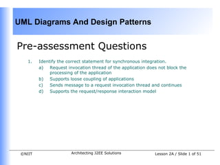
  • 1. UML Diagrams And Design Patterns Pre-assessment Questions 1. Identify the correct statement for synchronous integration. a) Request invocation thread of the application does not block the processing of the application b) Supports loose coupling of applications c) Sends message to a request invocation thread and continues d) Supports the request/response interaction model ©NIIT Architecting J2EE Solutions Lesson 2A / Slide 1 of 51
  • 2. UML Diagrams And Design Patterns Pre-assessment Questions 1. Consider the statements: Statement A: Queue-based communication involves a message sender sending a message to a message queue that is responsible for processing the message. Statement B: Queue-based communication involves a message sender sending a message to a message queue that is responsible for dispatching the message to a receiver. Identify the correct option. a) Statement A is True and statement B is False. b) Statement A is False and statement B is True. c) Both, statements A and B, are True. d) Both, statements A and B, are False. ©NIIT Architecting J2EE Solutions Lesson 2A / Slide 2 of 51
  • 3. UML Diagrams And Design Patterns Pre-assessment Questions • Which level of integration uses the integration frameworks and application programming interfaces to integrate two applications? a) Data level b) Application interface level c) Method level d) User interface level ©NIIT Architecting J2EE Solutions Lesson 2A / Slide 3 of 51
  • 4. UML Diagrams And Design Patterns Pre-assessment Questions 1. Being a System Analyst, you are responsible for integrating a J2EE application with a legacy system. You need to integrate the J2EE application and legacy system using their similar functional methods. Which option enables you to perform the specified task? a) User interface level integration b) Data level integration c) Method level integration d) Application interface level integration 2. Which technique defines a standard architecture for connecting a J2EE application server with different enterprise information system? a) Java native interface b) CORBA c) Web services d) J2EE Connector Architecture ©NIIT Architecting J2EE Solutions Lesson 2A / Slide 4 of 51
  • 5. UML Diagrams And Design Patterns Solutions to Pre-assessment Questions: 1. d. Supports the request/response interaction model 2. b. Statement A is false and statement B is true 3. b. Application interface level 4. c. Method level integration 5. d. J2EE Connector Architecture ©NIIT Architecting J2EE Solutions Lesson 2A / Slide 5 of 51
  • 6. UML Diagrams And Design Patterns Objectives In this lesson, you will learn to: • Model J2EE applications using UML diagrams • Identify the need for design patterns • Use creational design patterns ©NIIT Architecting J2EE Solutions Lesson 2A / Slide 6 of 51
  • 7. UML Diagrams And Design Patterns Modeling J2EE Applications Using UML • Case study: • NewTech Inc. is a retail bookstore that sells books of different categories such as science & technology, medicine, astronomy, novels, and children books. • As a part of its expansion plan, NewTech Inc. wants to go online and create an Online Bookstore System to attract customers from all over the globe. • Consider that NewTech Inc. names it online system as Online Bookstore System. The Website of the Online Bookstore System should list the books according to the categories that the books belong to. • The users of the Website should be able to browse through a catalog of books that is made available to them on the Website. Each book selected by the user should be listed in the user’s shopping cart. ©NIIT Architecting J2EE Solutions Lesson 2A / Slide 7 of 51
  • 8. UML Diagrams And Design Patterns Modeling J2EE Applications Using UML (Contd.) • Case study (Contd.): • The Website of the retail bookstore should support two kinds of users: registered and unregistered. The Website should allow the unregistered user to browse through the online retail bookstore and view the details of the books. • In addition, the unregistered users should be allowed to add books to their shopping cart. However, only the registered users should be allowed to make an online purchase. • Moreover, the registered users should have a different view of the retail bookstore, which includes informational messages customized to their interests. • The Website of NewTech Inc. should also sell books to its various retail stores. The company has an enormous market following and therefore, the Website of the company should be scalable enough to support large number of page hits per day. ©NIIT Architecting J2EE Solutions Lesson 2A / Slide 8 of 51
  • 9. UML Diagrams And Design Patterns Modeling J2EE Applications Using UML (Contd.) • The UML Diagrams that can be used to represent the structure and design of an enterprise application are: • Use case diagrams • Class diagrams • Package diagrams • Sequence diagrams • Collaboration diagrams • State diagrams • Activity diagrams • Component diagrams • Deployment diagrams ©NIIT Architecting J2EE Solutions Lesson 2A / Slide 9 of 51
  • 10. UML Diagrams And Design Patterns Modeling J2EE Applications Using UML (Contd.) • Using Use Case Diagram • Depicts the various operations that a system performs. • Contains use cases, actors, and their relationships. • Elements of a Use Case Diagram are: • Use Cases: Describe the behavior of a given system in textual format. • Actors: Represent the coherent set of roles that the users of a given system play while interacting with the use cases. ©NIIT Architecting J2EE Solutions Lesson 2A / Slide 10 of 51
  • 11. UML Diagrams And Design Patterns Modeling J2EE Applications Using UML (Contd.) • Using Use Case Diagram (Contd.) • Elements of a Use Case Diagram are (Contd.): • Relationships: Represents the interaction between the actors and the use cases. The two types of relationships are: • Extend: Indicates that an existing use case is extended by additional behavior to obtain another use case. • Include: Indicates that the functions of one use case are included in the functions of the other. • System boundary: Defines the limits of the given system. ©NIIT Architecting J2EE Solutions Lesson 2A / Slide 11 of 51
  • 12. UML Diagrams And Design Patterns Modeling J2EE Applications Using UML (Contd.) • Using Use Case Diagram (Contd.) • Analyzing the Use Cases and Actors • Use Case diagram for the Online Shopping System: ©NIIT Architecting J2EE Solutions Lesson 2A / Slide 12 of 51
  • 13. UML Diagrams And Design Patterns Modeling J2EE Applications Using UML (Contd.) • Using Use Case Diagram (Contd.) • A use case specification document includes information, such as: • Actors: Specifies the participants of use cases. • Pre-conditions: Specifies the prerequisites to be met. • Post-conditions: Specifies the actions to be performed. • Basic flow: Lists the basic events that will occur when a use case is executed. • Alternative flows: Lists the subsidiary events that occurs in use case. • Special Requirements: Specifies the success and failure scenarios of business rules for the basic and alternative flows of events. • Use case relationships: Specifies the relationships that exist between the various use cases. ©NIIT Architecting J2EE Solutions Lesson 2A / Slide 13 of 51
  • 14. UML Diagrams And Design Patterns Modeling J2EE Applications Using UML (Contd.) • Using Class Diagram • Represents the static design view of a system. • Includes a set of classes and interfaces along with the collaborations and relationships among the classes and interfaces. • The three types of classes that realize the behavior specified in the use case are: • Boundary class: Represents the interface between the actors and the given system. • Control class: Represents the use case logic and coordinates with other classes in the given system. • Entity class: Manages the information that a given system requires to provide a specific functionality. ©NIIT Architecting J2EE Solutions Lesson 2A / Slide 14 of 51
  • 15. UML Diagrams And Design Patterns Modeling J2EE Applications Using UML (Contd.) • Using Class Diagram (Contd.) • Elements of a Class Diagram are: • Class: Represents an entity of a given system that provides an encapsulated implementation of business functionality for a given system. • Interface: Represents an entity of a given system that provides only the declaration of implementing business functionality. • Relation: Defines a logical connection between classes and interfaces of a given system. ©NIIT Architecting J2EE Solutions Lesson 2A / Slide 15 of 51
  • 16. UML Diagrams And Design Patterns Modeling J2EE Applications Using UML (Contd.) • Using Class Diagram (Contd.) • Class diagram for the Online Shopping System: ©NIIT Architecting J2EE Solutions Lesson 2A / Slide 16 of 51
  • 17. UML Diagrams And Design Patterns Modeling J2EE Applications Using UML (Contd.) • Using Package Diagram • Represents the grouping of related boundary, control, and entity classes of a given system. • Is similar to namespaces such that you can store classes with the same name in two different packages. • Elements of a Package Diagram are: • Packages: Refer to the grouping of similar elements. In J2EE environment, you group the classes with similar function in a package. • Relationships: Define a logical connection between various packages in a given system. ©NIIT Architecting J2EE Solutions Lesson 2A / Slide 17 of 51
  • 18. UML Diagrams And Design Patterns Modeling J2EE Applications Using UML (Contd.) • Using Package Diagram (Contd.) • Package diagram for the Online Bookstore System: ©NIIT Architecting J2EE Solutions Lesson 2A / Slide 18 of 51
  • 19. UML Diagrams And Design Patterns Modeling J2EE Applications Using UML (Contd.) • Using Sequence Diagram • Represents the interaction between the objects of a system in the form of messages in a sequence by time. • Depicts the dynamic behaviour of a given system. • Elements of a Sequence Diagram are: • Objects: Refer to an instance of a class. • Messages: Refer to the interaction between the various objects in the sequence diagram. ©NIIT Architecting J2EE Solutions Lesson 2A / Slide 19 of 51
  • 20. UML Diagrams And Design Patterns Modeling J2EE Applications Using UML (Contd.) • Using Sequence Diagram (Contd.) • User login session sequence diagram for the Online BookStore System: ©NIIT Architecting J2EE Solutions Lesson 2A / Slide 20 of 51
  • 21. UML Diagrams And Design Patterns Modeling J2EE Applications Using UML (Contd.) • Using Collaboration Diagram • Represents the interaction between objects of a system in the form of messages. • Elements of a Collaboration Diagram are: • Objects: Refer to an instance of a class. • Messages: Refer to the interaction between the various objects as arrows in the collaboration diagram. . • Relations: Refer to the line associated with the objects of a given system. ©NIIT Architecting J2EE Solutions Lesson 2A / Slide 21 of 51
  • 22. UML Diagrams And Design Patterns Modeling J2EE Applications Using UML (Contd.) • Using Collaboration Diagram (Contd.) • User login session collaboration diagram for the Online BookStore System: ©NIIT Architecting J2EE Solutions Lesson 2A / Slide 22 of 51
  • 23. UML Diagrams And Design Patterns Modeling J2EE Applications Using UML (Contd.) • Using State Diagram • Shows how the object of a system reacts when an event occurs. • Depicts the business flow of an object of a given system. • Elements of a State Diagram are: • Initial state: Refers to the first activity in a flow and is represented by a solid circle. • State: Refers to the state of an object at a specific instance of time. • Transition: Refers to the transition from one state to another and is represented by an arrow. • Event/Action: Refers to a user- or system-generated action that causes a transition to occur. • Final state: Refers to the last activity in a flow and is represented by a bull’s eye symbol. ©NIIT Architecting J2EE Solutions Lesson 2A / Slide 23 of 51
  • 24. UML Diagrams And Design Patterns Modeling J2EE Applications Using UML (Contd.) • Using State Diagram (Contd.) • User login session state diagram for the Online BookStore System: ©NIIT Architecting J2EE Solutions Lesson 2A / Slide 24 of 51
  • 25. UML Diagrams And Design Patterns Modeling J2EE Applications Using UML (Contd.) • Using Activity Diagram • Represents the dynamic view of a system that depicts the flow of control of objects from one activity to another. • Represents the business and operational workflows of a given system. • Elements of an Activity Diagram are: • Initial Activity: Refers to the first activity in a flow and is represented by a solid circle. • Activity: Refers to an action in a flow and is represented with a rectangle with rounded corners. • Decisions: Refers to the business logic where a decision is taken. • Final Activity: Refers to the last activity in a flow and is represented by a bull’s eye symbol. ©NIIT Architecting J2EE Solutions Lesson 2A / Slide 25 of 51
  • 26. UML Diagrams And Design Patterns Modeling J2EE Applications Using UML (Contd.) • Using Activity Diagram (Contd.) • Order processing activity diagram for the Online BookStore System: ©NIIT Architecting J2EE Solutions Lesson 2A / Slide 26 of 51
  • 27. UML Diagrams And Design Patterns Modeling J2EE Applications Using UML (Contd.) • Using Component Diagram • Represents the grouping of packages and other components of a system along with their relationship with each other. • Represents the implementation of a given system. • Elements of a Component Diagram are: • Components: Refer to the entities that interact with each other in a given system. • Class/Interface/Object: Represents entities of a given system that forms a part of the component. • Relation/Association: Defines a logical connection between various components of a given system. ©NIIT Architecting J2EE Solutions Lesson 2A / Slide 27 of 51
  • 28. UML Diagrams And Design Patterns Modeling J2EE Applications Using UML (Contd.) • Using Component Diagram (Contd.) • Order processing component diagram for the Online BookStore System: ©NIIT Architecting J2EE Solutions Lesson 2A / Slide 28 of 51
  • 29. UML Diagrams And Design Patterns Modeling J2EE Applications Using UML (Contd.) • Using Deployment Diagram • Represents the configuration of run-time processing nodes and the components that reside on the node. • Provides a complete deployment environment for the given system, which is easy to comprehend. • Elements of a Deployment Diagram are: • Nodes: Represent the elements that provide an execution environment for the various components of a given system. • Relation: Represents the interconnection between various nodes of a given system. ©NIIT Architecting J2EE Solutions Lesson 2A / Slide 29 of 51
  • 30. UML Diagrams And Design Patterns Modeling J2EE Applications Using UML (Contd.) • Using Deployment Diagram (Contd.) • The deployment diagram for the Online BookStore System: ©NIIT Architecting J2EE Solutions Lesson 2A / Slide 30 of 51
  • 31. UML Diagrams And Design Patterns Creating a UML Diagram • Problem Statement • MetalTech US Engineering Inc. has an online product information system for its product designers. The product designers are located in different parts of country. The products are identified as metallic and non-metallic products. The information about a product includes attributes, such as product_id, product_name, product_type, and product_picture. A collection of assembled products form an assembly, which is identified by the attributes, assembly_id, and assembly_name. In the product information system, the part forming an assembly is known as Bill of Material (BOM). While creating the BOM, the product designer at the server end can add and remove the product parts from an assembly, as the structure of assemblies change frequently. Draw the use case diagram, class diagram, and sequence diagram for modeling the online product information system. ©NIIT Architecting J2EE Solutions Lesson 2A / Slide 31 of 51
  • 32. UML Diagrams And Design Patterns Creating a UML Diagram (Contd.) • Solution 1. Identify use cases. 2. Identify actors. 3. Draw use case diagram. 4. Draw class diagram. 5. Draw sequence diagram. ©NIIT Architecting J2EE Solutions Lesson 2A / Slide 32 of 51
  • 33. UML Diagrams And Design Patterns Overview of Patterns • Patterns • Is a proven solution to a problem in a given context. • Is first verified several times in the real-world systems to be actually called a pattern. • Promotes reuse of software concepts and technologies, which make you work faster and efficiently. ©NIIT Architecting J2EE Solutions Lesson 2A / Slide 33 of 51
  • 34. UML Diagrams And Design Patterns Overview of Patterns (Contd.) • About GoF’s Design Patterns • The four elements of GoF’s design patterns are: • Pattern name: Identifies a pattern. • Problem: Describes when to apply a pattern and the context in which to apply the pattern. • Solution: Describes a pattern as a template, which can be applied to different contexts. • Consequences: Describes the pros and cons in applying the pattern in a certain context. ©NIIT Architecting J2EE Solutions Lesson 2A / Slide 34 of 51
  • 35. UML Diagrams And Design Patterns Overview of Patterns (Contd.) • About GoF’s Design Patterns (Contd.) • The advantages of using design patterns are: • Allows reusing the experience of predecessors. • Communicates the knowledge gained from experience. • Establishes common terminology for problems. • Provides solutions to real-world problems. • Captures knowledge and documenting best practices for a domain. • Documents the decision along with the rationale that leads to the solution. • Describes the circumstances, influences, and the resolution of a solution. • Facilitates design modifications, documentation, and understandability of a software system. ©NIIT Architecting J2EE Solutions Lesson 2A / Slide 35 of 51
  • 36. UML Diagrams And Design Patterns Overview of Patterns (Contd.) • Types of GoF’s Design Patterns • The three types of design patterns are: • Creational design patterns: Provide techniques for creating objects • Structural design patterns: Describe the composition of objects and their organization. • Behavioral design patterns: Provide guidelines for enabling communication among objects of a given system. ©NIIT Architecting J2EE Solutions Lesson 2A / Slide 36 of 51
  • 37. UML Diagrams And Design Patterns Overview of Patterns (Contd.) • Creational Design Patterns • Supports the creation of class instances. • Allows instances of classes to be created, without the need to identify the class type by having the subclass of the class create the objects. • Hides the details of the class to be instantiated from the calling class, by using an abstract class. ©NIIT Architecting J2EE Solutions Lesson 2A / Slide 37 of 51
  • 38. UML Diagrams And Design Patterns Creational Design Pattern • Abstract Factory Pattern • Provides an interface to create families of related or dependent classes without declaring their concrete classes. • Consists of an abstract class along with a couple of subclasses that provide the implementations of the abstract class. • Allows the clients to use the classes only through their abstract classes. • Advantages of using abstract factory pattern are: • Isolates the implementation of concrete classes from the user. • Enables easy exchange of families of objects. • Ensures consistency among the families of objects. ©NIIT Architecting J2EE Solutions Lesson 2A / Slide 38 of 51
  • 39. UML Diagrams And Design Patterns Creational Design Pattern (Contd.) • Builder Pattern • Separates the construction of a complex object from its representation to enable the same construction process to create different objects. • Allows a client object to create a complex object by specifying only its type and content. • Defines an interface to create an object, but allows the subclass to decide which class to instantiate for the creation of an object. • Enables you to: • Change the internal representation of an object. • Separate the code of construction from the code of representation. • Control the construction process. ©NIIT Architecting J2EE Solutions Lesson 2A / Slide 39 of 51
  • 40. UML Diagrams And Design Patterns Creational Design Pattern (Contd.) • Builder Pattern (Contd.) • Object diagram depicting builder pattern: ©NIIT Architecting J2EE Solutions Lesson 2A / Slide 40 of 51
  • 41. UML Diagrams And Design Patterns Creational Design Pattern (Contd.) • Factory Method Pattern • Defines an interface to create an object but allows the subclasses to decide the class to be instantiated. • Helps construct individual objects for a specific purpose by deferring the instantiation to subclasses. • Enables addition of new classes without the need to modify the code, as the new class only needs to implement an interface. ©NIIT Architecting J2EE Solutions Lesson 2A / Slide 41 of 51
  • 42. UML Diagrams And Design Patterns Creational Design Pattern (Contd.) • Factory Method Pattern (Contd.) • Object diagram depicting factory method pattern: ©NIIT Architecting J2EE Solutions Lesson 2A / Slide 42 of 51
  • 43. UML Diagrams And Design Patterns Creational Design Pattern (Contd.) • Prototype Pattern • Provides a way to dynamically select the instantiation of an object and to return a clone of a prototypical object. • Is used when it is time-consuming to instantiate a highly complex class. • The advantages of using prototype pattern are: • Enables run-time addition or removal of objects. • Hides the concrete product classes from the client. ©NIIT Architecting J2EE Solutions Lesson 2A / Slide 43 of 51
  • 44. UML Diagrams And Design Patterns Creational Design Pattern (Contd.) • Prototype Pattern (Contd.) • Object diagram depicting prototype pattern: ©NIIT Architecting J2EE Solutions Lesson 2A / Slide 44 of 51
  • 45. UML Diagrams And Design Patterns Creational Design Pattern (Contd.) • Singleton Pattern • Ensures that a class has only a single instance and provides a global point of access to it. • Ensures all the objects that use the instance of the class use the same instance. • Is used when exactly a single instance of a class should exist. ©NIIT Architecting J2EE Solutions Lesson 2A / Slide 45 of 51
  • 46. UML Diagrams And Design Patterns Creational Design Pattern (Contd.) • Singleton Pattern (Contd.) • The advantages of using singleton pattern are: • Controls the access to the single instance of a class. • Lessens the use of namespaces. • Enables refinement of class operations and representation. • Allows variable number of class instances to exist. • Object diagram depicting singleton pattern: ©NIIT Architecting J2EE Solutions Lesson 2A / Slide 46 of 51
  • 47. UML Diagrams And Design Patterns Identifying Creational Design Patterns • Problem Statement: • In the online product information system of Mastery Mechanics Engineering Inc., the product designer needs to brief the developer the kind of patterns that he/she can implement while developing the code so as to optimize the code. Identify the various creational patterns that can be applied to the above case study. ©NIIT Architecting J2EE Solutions Lesson 2A / Slide 47 of 51
  • 48. UML Diagrams And Design Patterns Identifying Creational Design Patterns (Contd.) • Solution 1. Identify the Builder design pattern. 2. Identify the Factory Method design pattern. 3. Identify the Prototype pattern. 4. Identify the Singleton pattern. ©NIIT Architecting J2EE Solutions Lesson 2A / Slide 48 of 51
  • 49. UML Diagrams And Design Patterns Summary In this lesson, you learned: • The structure and design of an enterprise application can be represented by identifying the elements and analyzing the following nine UML diagrams: • Use case diagram: Depicts the various operations that a system performs. • Class diagram: Depicts the static design view of a system. It includes a set of classes and interfaces along with the collaborations and relationships among the classes and interfaces. • Package diagram: Depicts the grouping of related classes and interfaces of a given system. • Sequence diagram: Depicts the interaction between the objects of a system in the form of messages in a sequence by time. • Collaboration diagram: Depicts the interaction between objects of a system in the form of messages. • State diagram: Depicts how the object of a system reacts when an event occurs. ©NIIT Architecting J2EE Solutions Lesson 2A / Slide 49 of 51
  • 50. UML Diagrams And Design Patterns Summary (Contd.) • Activity diagram: Depicts the dynamic view of a system, showing the flow of control of the objects from one activity to another. • Component diagram: Depicts the grouping of packages and other components of a system, and their relationship with each other. • Deployment diagram: Depicts a deployment diagram that represents the configuration of the run-time processing nodes and the components that reside on the node. • Patterns are defined as proven solutions to problems in a given context. • The important elements of the GoF’s design patterns are pattern name, problem, solution, and consequences. • The advantages of using the design patterns in providing solutions to the real-world problems. • The GoF’s design patterns are categorized into three types, based on their purpose and scope: ©NIIT Architecting J2EE Solutions Lesson 2A / Slide 50 of 51
  • 51. UML Diagrams And Design Patterns Summary (Contd.) • The GoF’s design patterns are categorized into three types, based on their purpose and scope: • Creational Design Patterns • Structural Design Patterns • Behavioral Design Patterns • The creational design patterns provide the techniques for creating objects. These patterns make a system independent of how the objects are created, composed, and represented. • The structural design patterns describe the composition and organization of the objects. • The behavioral design patterns provide the guidelines for enabling communication among various objects of a given system. • The various types of creational design patterns are abstract factory, builder, factory method, prototype, and singleton patterns. ©NIIT Architecting J2EE Solutions Lesson 2A / Slide 51 of 51