

Recomendados
Mais conteúdo relacionado
Semelhante a Lecture 16
Semelhante a Lecture 16 (18)
Mais de Lucian Nicolau
Lecture 16
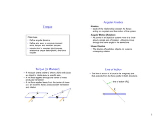
- 1. Angular Kinetics Torque Kinetics • study of the relationship between the forces acting on a system and the motion of the system Angular Motion (Rotation) Objectives: • All points in an object or system move in a circle • Define angular kinetics about a single axis of rotation. All points move • Define and learn to compute moment through the same angle in the same time arms, torque, and resultant torques Linear Kinetics • Introduction to resultant joint torques, • The kinetics of particles, objects, or systems anatomical torque descriptions, and force undergoing rotation couples Torque (or Moment) Line of Action • A measure of the extent to which a force will cause • The line of action of a force is the imaginary line an object to rotate about a specific axis that extends from the force vector in both directions • A net force applied through the center of mass produces translation • A net force applied away from the center of mass line of action of F (i.e. an eccentric force) produces both translation and rotation F F F 1
- 2. Moment Arm Computing a Moment Arm • Shortest distance from a force’s line of action to the • Need to know: axis of rotation – distance (d) from axis of rotation to point at which • Moment arm is always perpendicular to the line of force is applied action and passes through the axis of rotation – angle (θ) at which force is applied • Use trigonometry to compute moment arm (d⊥) line of action of F d⊥ = d sin θ 90° moment arm of F F axis of rotation F θ axis of rotation d Moment Arm Examples Computing Torque • Torque has: axis of rotation d⊥ = d d – a magnitude – a direction (+ or –) θ – a specific axis of rotation d⊥= d sin θ F F • The magnitude of the torque (T) produced by a force is the product of the force’s magnitude (F) times the force’s moment arm (d⊥): axis of T = F d⊥ T = F d⊥ rotation d⊥ = d sin θ d⊥ = 0 θ F • Units: F d F d – English: foot-pounds (ft-lb) d⊥ – SI : Newton-meters (Nm) 2
- 3. Direction of a Torque Example Problem #1 • Positive torque : acts counterclockwise about the Shown below are 4 muscles acting across a joint. axis of rotation. Which muscles have the largest and smallest • Negative torque : acts clockwise about the axis force? moment arm? torque magnitude? • Determine direction using the right hand rule: 3 100 N 2 100 N – Place right hand on force vector, fingers towards arrow tip joint 50° – Curl fingers around axis of rotation 20° – Torque acts in direction that fingers are curled 60° 1 150 N 0.01 m T>0 T<0 limb segment 0.02 m 90° axis of F F 0.04 m rotation 4 35 N Torque Composition Resultant Joint Torque • Process of determining a single resultant (or net) torque from two or more torques. • The effects of all forces acting about a joint can be • Performed by adding the torques together, taking the duplicated exactly by the combination of: sign (direction) of the torque into account – A resultant joint force acting at the joint center • Resultant torque has same effect on rotation as the – A resultant joint torque acting about the axis of individual torques acting together rotation through the joint center T3 T net = |T 1| – |T 2| + |T 3| • Resultant joint force is the vector composition of all F3 forces acting across a joint. T1 • Resultant joint torque is the composition of the axis of torques produced about the joint axis by these forces. rotation T2 • Note: Forces that do not act across the joint (e.g. F1 F2 weight) are not included in the resultant joint force or torque. Note: |T| = magnitude of torque T (≥ 0) 3
- 4. Example Use of Resultant Joint Torque • Typically, joint contact force, muscle forces, ligament Fcontact forces, etc. cannot be determined individually Tresultant Fresultant • We can compute resultant joint forces and torques Facl d ⊥acl based on data measured external to the body knee joint center • Except near the limits of the anatomical range of d ⊥quads Fquads Fquads Fcontact motion, the main contributors to the resultant joint d ⊥hams Fhams torque are the muscles tibia • The resultant joint torque provides a simplified picture Facl Fhams of which muscle groups are most active about a joint Tresultant = (Fquads d⊥quads) + (F acl d⊥acl) – (Fhams d⊥hams) Example Problem #2 Force Couple Shown is a forearm with 2 elbow flexors and 1 • For pure rotation about the center of mass, the center elbow extensor. Find the resultant joint torque for of mass must remain stationary from Newton’s 1st the 3 combinations of forces shown in the table: law, the net force on the object must equal zero • Force couple : Two forces of equal magnitude, Ft 0 0 32 Ft Fcontact Fbi applied in opposite directions. Produce pure rotation Fbr about the center of mass. Fcontact 8 3.2 46.4 T = F (d⊥1 + d ⊥2 ) 30° F Fbi 16 10 20 0.025 m 0.05 m d⊥2 0.10 m W=8N d⊥1 Fbr 0 2.4 4.8 ΣF=0 0.25 m F RJT Force Couple Net Effect 4
- 5. Anatomical Torques • Positive & negative torques depend on frame of reference chosen: y y Fquad Fquad knee knee T>0 T<0 x x • To avoid this problem, joint torques are typically described by the joint motion that would occur if the segment moved in the direction of the torque (e.g. Fquad produces a knee extension torque) 5