
Recomendados
Mais conteúdo relacionado
Mais procurados
Mais procurados (20)
Semelhante a Bottle Line Simulation Logic in LogixPro
Semelhante a Bottle Line Simulation Logic in LogixPro (20)
Último
Último (20)
Bottle Line Simulation Logic in LogixPro
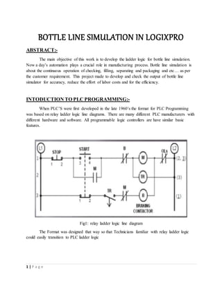
- 1. 1 | P a g e BOTTLE LINE SIMULATION IN LOGIXPRO ABSTRACT:- The main objective of this work is to develop the ladder logic for bottle line simulation. Now a day’s automation plays a crucial role in manufacturing process. Bottle line simulation is about the continuous operation of checking, filling, separating and packaging and etc… as per the customer requirement. This project made to develop and check the output of bottle line simulator for accuracy, reduce the effort of labor costs and for the efficiency. INTODUCTION TO PLC PROGRAMMING:- When PLC’S were first developed in the late 1960’s the format for PLC Programming was based on relay ladder logic line diagrams. There are many different PLC manufacturers with different hardware and software. All programmable logic controllers are have similar basic features. Fig1: relay ladder logic line diagram The Format was designed that way so that Technicians familiar with relay ladder logic could easily transition to PLC ladder logic
- 2. 2 | P a g e Fig2: PLC Ladder logic This is the same ladder logic as a line diagram and as a PLC Program LOGIXPRO:- LogixPro allows you to practice and develop your RS Logix programming skills where and when you want. It contains a RS logix editor which allows you to create and edit ladder logic. It contains a software PLC emulator which we simply call PLC. The PLC have same functionality as Allen Bradly PLC. It contains pro simll simulations package. This is the collection of programs using many of the same basic programming instructions utilized by Allen Bradly RS logix 500software simulations of real world equipment that are graphically depicted on your system screen. Edit panel provides easy access to all RS logix instructions and they are simply drag and drop type. In PLC panel having adjustable speed drive also. This is not a component of normal PLC’s, but is provided in logixpro so that you may adjust the speed of the simulations to suit your particular computer. Set the scan slow enough and you can easily monitor how your program instructions are responding. The control devices are programmed as inputs. The symbols are the same as those for normally open (NO) and normally closed (NC) contacts. The loads are programmed as outputs. The physical input and output devices are connected to terminals on PLC I/O cards. The address indicates whether the connection is an input or an output, the card number and the number of the termination point.
- 3. 3 | P a g e An address does not have to represent a physical input or output. It can refer to a single bit in memory that can be used as a control as it changes state (1or0), or it can represent some other function such as a timer or counter, or it can specify a type of number like integer or floating point. A list of input and output type can be viewed in the data table S2 - STATUS B3 – BINARY T4 – TIMER C5 – COUNTER R6 – CONTROL N7 – INTEGER F8 – FLOAT Addresses are available from 0 to 15; a 16-bit word. You can select from 100 words; from 0 to 99 and the status of bit can be monitored in the data table. Fig3: data table with binary table The address follows a format 𝑇𝑌𝑃𝐸: 𝑊𝑂𝑅𝐷/𝐵𝐼𝑇 E.g. I: 3/5, O: 2/1, T4:5/14…...
- 4. 4 | P a g e Fig4: Logixpro screen The most commonly used elements of LogixPro are displayed below. The Edit Panel provides easy access to all the RSLogix instructions and they may be simply dragged and dropped into your program. Once your program is ready for testing, clicking on the "Toggle Button" of the Edit Panel will bring the PLC Panel into view. From the PLC Panel you can download your program to the "PLC" and then place it into the "RUN" mode. This will initiate the scanning of your program and the I/O of your chosen simulation. Editing Your Program If you’re familiar with Windows and how to use a mouse, then you are going to find editing a breeze. Both Instructions and Rungs are selected simply by clicking on them with the left mouse button. Deleting is then just a matter of hitting the Del key on your keyboard. Double Clicking with the left mouse button allows you to edit an instruction's address while right clicking displays a pop-up menu of related editing commands. Click on an Instruction or Rung with the left mouse button and keep it held down and you will be able to drag it wherever you please.
- 5. 5 | P a g e In logixpro software having a set of exercises with covering of all elements of instructions. In this, I am giving detail info about bottle line simulation. Once you open the software LOGIXPRO in menu bar click on simulations and double click on bottle line simulation for opening the HMI SCREEN. After clicking the bottle line simulator open HMI screen on left side of the screen and the right side of the screen is for designing the ladder logic. The elements require to design are located in edit panel. Once complete the logic click on toggle switch which is at right top of edit panel then appears the PLC panel then download your logic to plc and put in on run mode to check the output. Before we design a ladder logic for bottle line simulation we have to know some are used in this instructions which logic. LIM test is the instruction for test the values within or outside a specified range depending on how you set the limits. TOD (convert to BCD) instruction to convert 16 bit integer into BCD value. BSL instruction is the output instruction that load date into a bit array one bit at a time. The data is shifted through the array then unloaded one bit at a time. Bottle line Simuator
- 6. 6 | P a g e Fig6: bottle line simulator HMI screen There are always numerous ways to accomplish tasks in programming, but a quick review of the Allen Bradley bit shift instructions should surely point to them as an ideal tool for use in this particular process. In the bottle line simulation, we are faced with detecting and tracking a few Boolean details having to do with the bottles entering the line. Sensors are provided to detect the presence of a new bottle, the bottle size, and whether the bottle is fully intact. Essentially 3 Boolean states describing the properties of each bottle that enters the line. If we analyze the various ways that we might process these bottles, it should quickly become apparent that we will have ample information for making such decisions, assuming we keep track of it. A single BSR or BSL instruction can be used to track a single Boolean state (0 or 1) which in-turn can describe a unique property of a product. In the initial exercise you will be asked to track the 3 Boolean values describing each bottle entering our process line.
- 7. 7 | P a g e The Boolean states will be referred to as "Exists", "Large", and "Broken" and these states are to be tracked by you, utilizing 3 separate BSL (bit shift left) instructions. It can be argued that "Exists" need not be tracked (=correct), as bottles continuously enter the line, and therefore must exist. We will even use this fact to strobe our BSL instructions and cause a shifting of our tracked information. Later when you start diverting broken bottles to scrap however, they will no-longer Exist. These missing bottles could be detected after they are scrapped by using the "Broken" state, but for now I want you to track all 3 states using 3 separate bit arrays. For these exercises please utilize the bits in word B3:0 if and when single bits such as flags etc. are required. Utilizing LS1 (Exists), strobe 3 BSL instructions to shift 3 separate bit arrays consisting of two 16 bit words each. Please use files #B3:2, #B3:4, and #B3:6 for this purpose. By restricting you to these particular files in the binary table, it will be much easier for you, and your instructor to monitor what is happening with your program using the data table display. Fig8: BSL instruction for exists, large, brake sensors
- 8. 8 | P a g e First we have to check the inputs and outputs for the given task. In this task when the operator switch on the START button the process starts and whenever he pushes the stop button the process should be stop at any time of instant. BSL instruction is to control the input given by sensors. In the hmi screen already assigned the input and outputs to the respective elements. When you’re designed the logic took the inputs and outputs from the screen just drag from the screen. Check the inputs and outputs at HMI screen and what are the elements present in the screen its purpose. In bottle line simulation screen having sensors, conveyors, motors, gates, bottles, display, NO, NC push buttons, selector switches, PLC… I indicate all the elements in the below figure with respective names. They are three conveyors main conveyor, scrap conveyor, divert conveyor. Each conveyor connected with motors. And one grinding motor and sensors, display, push buttons for start and stop and etc… Fig9: sensors in HMI Screen They are ten different sensors. Each sensor having its specified work. Exist sensor is to track the bottles, large sensor is to track the bottles with respective sizes, brake sensor is to track the broken bottles. Fill tube sensor is for check the bottle place for filling. Large, small fill sensors for fill the liquids by respective sizes. Cap sensor for fixing the caps. Scrap gate sensor is for diverting the broken bottle to grinder. Divert gate sensor is for divert thee large bottles. Scrap box sensor is for changing the box when it fills.
- 9. 9 | P a g e Fig10: conveyors They are three conveyors, first is main conveyor, the whole process id done on this conveyor. It is for moving the bottles in an order. Scrap conveyor is for when the box filled with crush pieces of bottles for the next box it will moves. Divert conveyor is for diverting the large bottles from the main conveyor with the help of divert gate. Fig11: gates & display They are two gates scrap gate and divert gate. Both are for diverting the bottles from main conveyor and display is for check the production count.
- 10. 10 | P a g e The total input and outputs are listed below Fig9: input and outputs OPERATION:- Track the bottles by exists sensor. Whether the bottle is broken then it goes to scrap. Fill the bottles by liquids with their respective sizes. After filling process, fixing the caps to the bottles. And then separating the bottles by sizes through divert gate. Ensure that the main conveyor movement and the filling operations are performed at a time. Once the scrap boxes filled up then the scrap conveyor moves for the next box When the operation starts check the display for production count.
- 11. 11 | P a g e
- 12. 12 | P a g e Fig: ladder logic for BOTTLE SIMULATION
- 13. 13 | P a g e When start button is ON run, main conveyor and grinder, divert conveyor will starts because they are continuous operations. For main conveyor, breaking timer (T: 4/0) done bit will assign due to main conveyor movement is proportional to the process of filling and caping. BSL instruction is to store the input in binary mode and (R: 6/bit) for controlling. When the brake sensor senses the bottle the binary bit stores the memory and the scrap gate will open when the bottle comes to the scrap gate. When the scrap box is fills scrap conveyor moves for the next box. When the scrap conveyor moving the scrap gate is in closed position. Assign counter (C5:0) for counting the broken bottles to fill the box. Here limit switch is used for the process will perform before the main conveyor movement. Here another counter (C5:1) is for counting the boxes. Once the box changes the two counters are resets by the instruction (RES). Rung 16 to 19 are for display the series connected counter counts the respective elements by its sensors. For the output TOD is connected. TOD instruction is to convert 16-bit integers into BCD values. PRECAUTIONS:- Check the STOP operation is working are not at any time of process. When the scrap conveyor is moving, scrap gate should be close. Divert conveyor should be continuous moving. Filling operation will perform with in the time period of main conveyor movement from one bottle to another bottle. REFERENCES:- LOGIXPRO SIMULATOR SOFTWARE file:///C:/program%20files%20(x86)/thelearningpit/logixpro/doc/bot/bottle.html http://thelearningpit.com. T.MOHAN KRISHNA, TECHMATION SOLUTIONS, HYDERABAD. THANKYOU