SlideShare uma empresa Scribd logo
1 de 10
Baixar para ler offline
2-111
2
CM160
CRANKSHAFT
NOTE: If any servicing of the connecting rods,
center bearings, or oil-injection pump drive gear is
necessary, Arctic Cat recommends that the crank-
shaft be taken to a qualified machine shop for that
service.
1. Wash the crankshaft with bearings in parts-clean-
ing solvent.
2. Inspect the bearings for wear, scoring, scuffing,
damage, or discoloration. Rotate the bearings.
Bearings must rotate freely and must not bind or
feel rough. If any abnormal condition is noted,
replace the bearing.
FC039
3. Inspect the connecting-rod bearings by rotating
them. The bearings must rotate freely and must not
bind or feel rough. If a connecting-rod bearing
must be replaced, the connecting rod and crank pin
must also be replaced.
FC040
4. Inspect the oil-injection pump drive gear for any
signs of worn or chipped teeth. If either condition
exists, replace the gear.
NOTE: Lubricate bearings thoroughly prior to
assembly.
REMOVING/INSTALLING OUTER
CRANKSHAFT BEARINGS
NOTE: The end bearings are not pressed onto
the crankshaft. The bearings can be removed sim-
ply by sliding them off the crankshaft.
CM161
Inspect the crankshaft bearing area for wear. If any
wear is noted on either end, replace the crankshaft end.
NOTE: Install the bearings by sliding each bear-
ing onto the crankshaft making sure the dowel-pin
hole in the outer race is properly positioned and
will align with its hole and pin in the crankcase.
CM161
! CAUTION
Water or parts-cleaning solvent must be used in
conjunction with the wet-or-dry sandpaper or dam-
age to the sealing surface may result.
Back to TOC Back to Section TOC NextBack
2-112
REED VALVE ASSEMBLY
1. Inspect the reed valves, stoppers, and valve blocks
for cracks or any deterioration.
CM162
2. Wash the reed valves, stopper, and cage assembly
in parts-cleaning solvent and blow dry.
3. Inspect the reed stopper height. Using a caliper,
measure the distance from the seat to the bottom
outer tip edge of the stopper. Measurement must
not exceed specifications. If measurement is not
within specifications, either bend or replace the
reed stopper.
CM163
4. Inspect the reed-to-seat clearance. Using a feeler
gauge, measure the clearance. Clearance must be
less than 0.20 mm (0.008 in.). If clearance is not
within specifications, replace the reed valve.
5. To assemble, place the reed valves on the cage
with its clipped corner positioned to the lower
right hand corner of the cage. Place the reed stop-
per assembly into position and secure with the
screws coated with red Loctite #271.
CM164A
Measuring Critical
Components
NOTE: Critical engine specifications charts can
be found in Section 1 of this manual.
CYLINDER HEAD VOLUME
(Squish-Gap Method)
To check the squish gap, a micrometer and two heavy
pieces of solder will be needed.
1. Remove the spark plugs from the engine.
2. Simultaneously insert two pieces of solder down
through the spark plug hole and push them up
against the inner cylinder bore towards the MAG-
side and PTO-side of the cylinder.
3. Pull the recoil rope and crank the engine over sev-
eral times while the solder is being held firmly in
place.
4. Remove both pieces of solder from the cylinder.
Using the micrometer, measure the very end of the
squeezed solder piece. Record the reading.
NOTE: If the solder hasn’t been squeezed by the
piston, a larger piece of solder must be used.
Repeat procedure.
5. Using the opposite end of the solder pieces, insert
them down through the spark plug hole towards the
PTO-side and MAG-side of the cylinder. Push on
the solder until they contact the inner cylinder bore.
6. Pull the recoil rope and crank the engine over sev-
eral times. Remove both pieces of solder from the
cylinder and measure the opposite squeezed ends
with a micrometer. Record reading.
NOTE: Measure from PTO to MAG-side of the pis-
ton to accurately measure the squish gap. Never
measure across piston, exhaust to carburetor
side, as the piston will rock and the reading won’t
be accurate.
Readings may vary from side to side.
Back to TOC Back to Section TOC NextBack
2-113
2
NOTE: Make sure the smaller reading is 1.5 mm
(0.059 in.) or less for the 800 cc or 1.49 mm (0.058
in.) or less for the 1000 cc.
CYLINDER TRUENESS
1. Measure each cylinder in the three locations from
front to back and side to side for a total of six read-
ings.
FC044
2. The trueness (out-of-roundness) is the difference
between the highest and lowest reading. Maxi-
mum trueness (out-of-roundness) must not exceed
0.1 mm (0.004 in.).
0725-586
PISTON SKIRT/CYLINDER
CLEARANCE
1. Measure each cylinder front to back about 2.5 cm
(1 in.) from the bottom of each cylinder.
2. Measure the corresponding piston skirt diameter at
a point 1 cm above the piston skirt at a right angle
to the piston-pin bore. Subtract this measurement
from the measurement in step 1. The difference
(clearance) must be within 0.075-0.0105 mm
(0.0029-0.0041 in.).
AC091
PISTON-RING END GAP
1. Place each piston ring in the wear portion above the
exhaust port of its respective cylinder. Use the pis-
ton to position each ring squarely in each cylinder.
2. Using a feeler gauge, measure each piston-ring
end gap. Acceptable ring end gap must be within
0.30-0.50 mm (0.012-0.0196 in.).
FC045
PISTON PIN AND PISTON-PIN BORE
1. Measure the piston pin diameter at each end and in
the center. Acceptable piston pin measurement
must be within 21.995-22.000 mm (0.8659-0.8661
in.) for the 800 cc or 23.995-24.000 mm (0.9447-
0.9449 in.) for the 1000 cc. If any measurement
varies by more than 0.02 mm (0.001 in.), the pis-
ton pin and bearing must be replaced as a set.
AN056
Back to TOC Back to Section TOC NextBack
2-114
2. Insert a snap gauge into each piston-pin bore; then
remove the gauge and measure it with a micrometer.
The diameter measurement must be within 22.002-
22.010 mm (0.8662-0.8665 in.) for the 800 cc or
24.002-24.010 mm (0.9450-0.9453 in.) for the 1000
cc. Take two measurements to ensure accuracy.
AC092
CONNECTING-ROD SMALL END
BORE
1. Insert a snap gauge into each connecting-rod small
end bore; then remove the gauge and measure it
with a micrometer.
AN061
2. The diameter measurement must be within
27.003-27.011 mm (1.0631-1.0634 in.) for the 800
cc or 29.003-29.011 mm (1.1410-1.1420 in.) for
the 1000 cc.
CRANKSHAFT RUNOUT
0742-727
1. Using the V Blocks, support the crankshaft on the
surface plate.
NOTE: The V blocks should support the crank-
shaft on the outer bearings.
2. Mount a dial indicator and base on the surface
plate. Position the indicator contact point against
the crankshaft location point A (PTO-end) from
the crankshaft end. Zero the indicator and rotate
the crankshaft slowly. Note the amount of crank-
shaft runout (total indicator reading).
NOTE: For runout location point specifications,
see Crankshaft Runout Specifications in Section 1
of this manual.
3. Position the indicator contact point against the
crankshaft location point B (MAG-end) from the
crankshaft end. Zero the indicator and rotate the
crankshaft slowly. Note the amount of crankshaft
runout (total indicator reading).
FC046
4. Position the indicator contact point against the
crankshaft at location point C (center). Zero the
indicator and rotate the crankshaft slowly. Note
the amount of crankshaft runout (total indicator
reading).
5. If runout exceeds 0.05 mm (0.002 in.) at any of the
checkpoints, the crankshaft must be either
straightened or replaced.
Assembling Engine
NOTE: The use of new gaskets and seals is rec-
ommended when assembling the engine.
NOTE: Before the engine is assembled, clean the
threads of the cap screws and the threaded areas
of the engine where loctite will be used.
NOTE: When the use of a lubricant is indicated,
use Arctic Cat Synthetic APV 2-Cycle Oil.
1. Apply a thin coat of grease to the inner seal lips of
the water pump seal.
Back to TOC Back to Section TOC NextBack
2-115
2
2. Using the seal driver, position the inner water
pump shaft seal onto the seal driver and gently tap
the seal down into position.
NOTE: Grease must be applied to the lips of the
inner seal before installation.
MS986A
NOTE: The seal must be installed with its spring
side towards the crankshaft.
3. Install the snap ring securing the inner seal in the
crankcase.
MS415
4. Using the seal driver, carefully install the outer
water pump seal. Gently tap the seal down into
position until it seats itself against its flange.
MS988
5. Apply a thin coat of grease to the sealing surface
of the oil-injection pump/water pump driveshaft;
then place the Oil Seal Protector Tool at the end of
the shaft. Twist the driveshaft clockwise as it is
pushed through the oil and water pump seals; then
remove the tool.
FS191
6. Position the shim on the oil-injection pump end of
the driveshaft.
CM159A
7. Secure the upper crankcase half upside-down on a
suitable support; then install the C-ring (A), the
four bearing retaining pins (B), and the two crank-
case dowel pins (C).
! CAUTION
Be very careful not to damage the seals when
installing the oil pump driveshaft. Be certain to use
the seal protector tool. Twist the driveshaft clock-
wise as it enters the seal area and while it is being
pushed through the seals.
Back to TOC Back to Section TOC NextBack
2-116
CM165C
8. Place the crankshaft end bearings into position
making sure the bearing retaining pin hole is posi-
tioned inward.
NOTE: The bearing retaining pin hole is the hole
that does not go entirely through the bearing case.
CM043A
9. Lubricate the inner lips of the crankshaft oil seals
with grease; then slide the seals onto the crank-
shaft making sure the spring side of each seal faces
inward.
NOTE: There is a MAG-side seal and a PTO-side
seal.
10. Apply oil to the crankshaft bearings; then install
the crankshaft into the upper crankcase half. Be
sure the alignment hole in each bearing is posi-
tioned over its respective dowel pin in the crank-
case; then seat the crankshaft.
CM045A
NOTE: To check the bearing for proper position,
place the point of a sharp tool into the dimple
found in the bearing race. Strike the tool with the
palm of the hand in either direction. If the bearing
moves, it isn’t positioned correctly and must be
rotated until it drops onto the dowel pin.
11. Position the two center seal rings with their end
gaps 180° apart (up on one and down on the
other); then apply a thin coat of High-Temp Seal-
ant to the entire bottom half of the crankcase seal-
ing surface.
CM036A
CM166
NOTE: Use only Arctic Cat High-Temp Sealant to
seal the crankcase halves.
12. Assemble the crankcase halves making sure that
the crankshaft gear and oil-injection pump drive-
shaft gears mesh. Rotate the crankshaft one full
turn to align the crankshaft gear and pump drive-
shaft.
13. Install the crankcase cap screws securing the
crankcase halves.
14. Tighten cap screws (1-10) in three steps to 31 ft-lb
using the appropriate pattern shown.
! CAUTION
If the bearings are not properly seated during
assembly, the crankcase halves will not seal tightly
and severe engine damage will result.
Back to TOC Back to Section TOC NextBack
2-117
2
742-198A
742-197A
15. On the 800 cc, tighten cap screw (11) to 8 ft-lb;
then turn the engine right-side up and tighten cap
screws (12-15) in three steps to 25 ft-lb.
16. On the 1000 cc, tighten cap screws (11-13) in three
steps to 25 ft-lb; then turn the engine right side up
and tighten cap screw (14) to 8 ft-lb.
NOTE: Secure the connecting rods with rubber
hoses.
17. Install the oil-injection pump retainer with a new
O-ring.
FC082
18. With the new O-ring in place, install the oil-injec-
tion pump making sure the pump shaft slot (A) and
pump driven gear shaft (B) align. Secure with two
screws (coated with blue Loctite #243). Tighten
the two screws to 8 ft-lb.
CM167A
NOTE: For assembly purposes, always use a new
O-ring lubricated with oil on the oil injection pump.
19. Install the oil-injection hoses and secure with the
clamps; then place the lower union assembly into
position and secure with new gaskets and union
cap screw. Tighten to 54 in.-lb.
CM153A
20. Secure the intake flanges, reed valve assemblies,
and gaskets with cap screws; then in a crisscross
pattern, tighten to 8 ft-lb.
21. Install the coolant temperature sensor and tighten
securely; then secure the sensor wire to the sensor
with a cable tie.
800 cc
1000 cc
! CAUTION
Be sure the oil-injection pump/water pump drive-
shaft is properly aligned with the slot of the oil-injec-
tion pump. The pump will be damaged if these two
components are not aligned.
! CAUTION
Always use new gaskets and assure that a gasket is
in place on each side of the union prior to securing
the union cap screw to the crankcase.
Back to TOC Back to Section TOC NextBack
2-118
CM172
22. Position the ceramic/rubber seal into the back side
of the water pump impeller with the ceramic face
of the seal directed out.
CM168
23. Using both thumbs, press the seal into position
making sure its marked side is positioned towards
the rubber seal cup; then apply a thin coat of
grease to the seal outer surface.
CM169
24. Place the impeller into position and secure with a
cap screw and washer. Be sure the rubber side of
the washer is lubricated with a light coat of grease
and directed toward the impeller. Apply blue Loc-
tite #243 to the threads of the cap screw and
tighten to 8 ft-lb.
25. Apply high-temperature sealant to the crankcase/
water pump cover seam; then install the dowel
pins into the crankcase.
CM171A
NOTE: Sealant is only required on the crankcase
seam.
CM171B
26. Apply a thin film of low-temp grease to the water
pump cover O-ring; then position the O-ring into
the water pump cover. With the alignment pins in
place, install the cover. Secure with seven screws
using the pattern shown. Tighten to 8 ft-lb.
0742-257
27. With the bypass valve of the thermostat directed to
the 12 o’clock position, install the thermostat and
housing; then in a crisscross pattern, tighten the
cap screws to 8 ft-lb.! CAUTION
The rubber side of the washer, which secures the
impeller, must be positioned toward the impeller. If
installed incorrectly, a coolant leak will result.
Back to TOC Back to Section TOC NextBack
2-119
2
CM157A
CM155A
28. Install the dowel pins into the crankcase; then
place the cylinder base gasket into position on the
crankcase.
29. Install the piston rings on each piston so the letter
on the top (inclined surface) of each ring faces the
dome of the piston.
726-306A
30. Apply oil to the connecting-rod small end bear-
ings; then install the small-end bearings. Install a
washer on each side of the connecting rod.
NOTE: The shoulder side of the washer must
seat to the needle bearing.
CM172A
31. Place each piston over the connecting rod so the
indicator dot on each piston will point toward the
intake/exhaust ports; then secure with an oiled pis-
ton pin.
NOTE: The indicator dot is found on the piston
dome.
CM173
32. Install the new circlips so the open end is directed
either up or down.
CM174
33. Rotate each piston ring until the ring ends are
properly positioned on either side of the ring
keeper; then apply oil to the piston assemblies and
cylinder bores. Remove the rubber hoses from the
connecting rods.
! CAUTION
Incorrect installation of the piston rings will result in
engine damage.
! CAUTION
Make sure the circlips are firmly seated and the open
end is directed either up or down before continuing
with assembly.
Back to TOC Back to Section TOC NextBack
2-120
34. In turn on each cylinder, place a piston holder (or
suitable substitute) beneath the piston skirt and
square the piston in respect to the crankcase; then
using a ring compressor or the fingers, compress
the rings and slide the cylinder over the piston.
Remove the piston holder and seat the cylinder
firmly onto the crankcase.
NOTE: The cylinders should slide on easily. DO
NOT force the pistons into the cylinders.
CM148
35. Secure each cylinder by installing the four nuts
and four new cap screws. DO NOT TIGHTEN AT
THIS TIME.
36. Apply a thin coat of high-temperature silicone
sealant to each exhaust port; then install the
exhaust gaskets.
37. Apply a thin coat of high-temperature silicone
sealant to the mating surfaces of the exhaust mani-
fold; then install the exhaust manifold and secure
with the eight nuts. Tighten the nuts using the pat-
tern shown to 17 ft-lb.
0742-292
NOTE: Always use new cap screws when install-
ing the cylinders.
38. Secure the cylinders (from step 35) by tightening
the cylinder base nuts and cap screws to 42 ft-lb in
three steps using the appropriate pattern shown.
0738-206
0738-220
39. Install the two cylinder O-rings on the top of each
cylinder making sure they are correctly positioned
in the grooves.
FC077
NOTE: Lubricating the cylinder O-rings with a
light coat of grease will help keep them seated in
the grooves of the cylinder.
40. Place new O-rings onto each of the head cap
screws. Place four of these cap screws (from oppo-
site end of each other) into the cylinder head.
Thread the spark plugs in part way; then while
holding the head above the cylinder, carefully start
and finger-tighten all four cap screws while
observing the cylinder O-rings to make sure they
remain in position. Slowly place the head into
position on top of the O-rings.
800 cc
1000 cc
Back to TOC Back to Section TOC NextBack

Mais conteúdo relacionado

Mais procurados

Procedure for Inspection Pistons and Cylinder Liners
Procedure for Inspection Pistons and Cylinder Liners Procedure for Inspection Pistons and Cylinder Liners
Procedure for Inspection Pistons and Cylinder Liners Erkut Denizci
 
Hyster l177 (h40 ft) forklift service repair manual
Hyster l177 (h40 ft) forklift service repair manualHyster l177 (h40 ft) forklift service repair manual
Hyster l177 (h40 ft) forklift service repair manualfujdjffjkskemme
 
Hitachi ex750 5 excavator service repair manual
Hitachi ex750 5 excavator service repair manualHitachi ex750 5 excavator service repair manual
Hitachi ex750 5 excavator service repair manualfjjskdmnenemm
 
Case ih 990 agricultural tractor service repair manual
Case ih 990 agricultural tractor service repair manualCase ih 990 agricultural tractor service repair manual
Case ih 990 agricultural tractor service repair manualjfjkskekemm
 
Case ih 990 agricultural tractor service repair manual instant download
Case ih 990 agricultural tractor service repair manual instant downloadCase ih 990 agricultural tractor service repair manual instant download
Case ih 990 agricultural tractor service repair manual instant downloadufjjsjekkemmme
 
Still r70 20 fork truck service repair manual
Still r70 20 fork truck service repair manualStill r70 20 fork truck service repair manual
Still r70 20 fork truck service repair manualfhjsekfksemert
 
Ch8 steering
Ch8 steeringCh8 steering
Ch8 steering_AXE_PM
 
Hyundai hl760 (#1001 #1301) wheel loader service repair manual
Hyundai hl760 (#1001 #1301) wheel loader service repair manualHyundai hl760 (#1001 #1301) wheel loader service repair manual
Hyundai hl760 (#1001 #1301) wheel loader service repair manualdfujdjkskekmmd
 
Hyster f005 (h5.00 xl) forklift service repair manual
Hyster f005 (h5.00 xl) forklift service repair manualHyster f005 (h5.00 xl) forklift service repair manual
Hyster f005 (h5.00 xl) forklift service repair manualfudjsjfekskkem
 
Hyundai hl780 9 wheel loader service repair manual
Hyundai hl780 9 wheel loader service repair manualHyundai hl780 9 wheel loader service repair manual
Hyundai hl780 9 wheel loader service repair manualdfujdjkskekmmd
 
HITACHI EX750-5 EXCAVATOR Service Repair Manual
HITACHI EX750-5 EXCAVATOR Service Repair ManualHITACHI EX750-5 EXCAVATOR Service Repair Manual
HITACHI EX750-5 EXCAVATOR Service Repair Manualjksmend skjdkmd
 

Mais procurados (13)

Procedure for Inspection Pistons and Cylinder Liners
Procedure for Inspection Pistons and Cylinder Liners Procedure for Inspection Pistons and Cylinder Liners
Procedure for Inspection Pistons and Cylinder Liners
 
Hyster l177 (h40 ft) forklift service repair manual
Hyster l177 (h40 ft) forklift service repair manualHyster l177 (h40 ft) forklift service repair manual
Hyster l177 (h40 ft) forklift service repair manual
 
Hitachi ex750 5 excavator service repair manual
Hitachi ex750 5 excavator service repair manualHitachi ex750 5 excavator service repair manual
Hitachi ex750 5 excavator service repair manual
 
Case ih 990 agricultural tractor service repair manual
Case ih 990 agricultural tractor service repair manualCase ih 990 agricultural tractor service repair manual
Case ih 990 agricultural tractor service repair manual
 
Case ih 990 agricultural tractor service repair manual instant download
Case ih 990 agricultural tractor service repair manual instant downloadCase ih 990 agricultural tractor service repair manual instant download
Case ih 990 agricultural tractor service repair manual instant download
 
Still r70 20 fork truck service repair manual
Still r70 20 fork truck service repair manualStill r70 20 fork truck service repair manual
Still r70 20 fork truck service repair manual
 
Clutch
ClutchClutch
Clutch
 
Ch8 steering
Ch8 steeringCh8 steering
Ch8 steering
 
Hyundai hl760 (#1001 #1301) wheel loader service repair manual
Hyundai hl760 (#1001 #1301) wheel loader service repair manualHyundai hl760 (#1001 #1301) wheel loader service repair manual
Hyundai hl760 (#1001 #1301) wheel loader service repair manual
 
Hyster f005 (h5.00 xl) forklift service repair manual
Hyster f005 (h5.00 xl) forklift service repair manualHyster f005 (h5.00 xl) forklift service repair manual
Hyster f005 (h5.00 xl) forklift service repair manual
 
Tablas de torque
Tablas de torqueTablas de torque
Tablas de torque
 
Hyundai hl780 9 wheel loader service repair manual
Hyundai hl780 9 wheel loader service repair manualHyundai hl780 9 wheel loader service repair manual
Hyundai hl780 9 wheel loader service repair manual
 
HITACHI EX750-5 EXCAVATOR Service Repair Manual
HITACHI EX750-5 EXCAVATOR Service Repair ManualHITACHI EX750-5 EXCAVATOR Service Repair Manual
HITACHI EX750-5 EXCAVATOR Service Repair Manual
 

Semelhante a Pg0171 п

Jcb 8290 fastrac (agricultural tractor) service repair manual (from 1351000 t...
Jcb 8290 fastrac (agricultural tractor) service repair manual (from 1351000 t...Jcb 8290 fastrac (agricultural tractor) service repair manual (from 1351000 t...
Jcb 8290 fastrac (agricultural tractor) service repair manual (from 1351000 t...hfjsekekmmd
 
Jcb 8290 fastrac (agricultural tractor) service repair manual (from 1351000 t...
Jcb 8290 fastrac (agricultural tractor) service repair manual (from 1351000 t...Jcb 8290 fastrac (agricultural tractor) service repair manual (from 1351000 t...
Jcb 8290 fastrac (agricultural tractor) service repair manual (from 1351000 t...udfjjkskekmee
 
Jcb 8330 fastrac (agricultural tractor) service repair manual (from 1351000 t...
Jcb 8330 fastrac (agricultural tractor) service repair manual (from 1351000 t...Jcb 8330 fastrac (agricultural tractor) service repair manual (from 1351000 t...
Jcb 8330 fastrac (agricultural tractor) service repair manual (from 1351000 t...fujsjefjskekemm
 
Jcb 8330 fastrac (agricultural tractor) service repair manual (from 1351000 t...
Jcb 8330 fastrac (agricultural tractor) service repair manual (from 1351000 t...Jcb 8330 fastrac (agricultural tractor) service repair manual (from 1351000 t...
Jcb 8330 fastrac (agricultural tractor) service repair manual (from 1351000 t...fusjjjsekkekm
 
Jcb 8330 fastrac (agricultural tractor) service repair manual (from 1351000 t...
Jcb 8330 fastrac (agricultural tractor) service repair manual (from 1351000 t...Jcb 8330 fastrac (agricultural tractor) service repair manual (from 1351000 t...
Jcb 8330 fastrac (agricultural tractor) service repair manual (from 1351000 t...udfjjkskekmee
 
Jcb 8330 fastrac (agricultural tractor) service repair manual (from 1351000 t...
Jcb 8330 fastrac (agricultural tractor) service repair manual (from 1351000 t...Jcb 8330 fastrac (agricultural tractor) service repair manual (from 1351000 t...
Jcb 8330 fastrac (agricultural tractor) service repair manual (from 1351000 t...hfjsekekmmd
 
Jcb 8290 fastrac (agricultural tractor) service repair manual (from 1351000 t...
Jcb 8290 fastrac (agricultural tractor) service repair manual (from 1351000 t...Jcb 8290 fastrac (agricultural tractor) service repair manual (from 1351000 t...
Jcb 8290 fastrac (agricultural tractor) service repair manual (from 1351000 t...fujsjefjskekemm
 
Jcb 8290 fastrac (agricultural tractor) service repair manual (from 1351000 t...
Jcb 8290 fastrac (agricultural tractor) service repair manual (from 1351000 t...Jcb 8290 fastrac (agricultural tractor) service repair manual (from 1351000 t...
Jcb 8290 fastrac (agricultural tractor) service repair manual (from 1351000 t...fusjjjsekkekm
 
Jcb 18 z 1 mini excavator service repair manual sn from 2493516 to 2493975
Jcb 18 z 1 mini excavator service repair manual sn from 2493516 to 2493975Jcb 18 z 1 mini excavator service repair manual sn from 2493516 to 2493975
Jcb 18 z 1 mini excavator service repair manual sn from 2493516 to 2493975fujsjfskekmm
 
Jcb 19 c 1 mini excavator service repair manual sn from 2492571 to 2493515
Jcb 19 c 1 mini excavator service repair manual sn from 2492571 to 2493515Jcb 19 c 1 mini excavator service repair manual sn from 2492571 to 2493515
Jcb 19 c 1 mini excavator service repair manual sn from 2492571 to 2493515fjjskeqwekfksmemm
 
Jcb 19 c 1 mini excavator service repair manual sn from 2492571 to 2493515
Jcb 19 c 1 mini excavator service repair manual sn from 2492571 to 2493515Jcb 19 c 1 mini excavator service repair manual sn from 2492571 to 2493515
Jcb 19 c 1 mini excavator service repair manual sn from 2492571 to 2493515fjskekxcddmmme
 
Jcb 19 c 1 pc mini excavator service repair manual sn from 2493976 to 2494335
Jcb 19 c 1 pc mini excavator service repair manual sn from 2493976 to 2494335Jcb 19 c 1 pc mini excavator service repair manual sn from 2493976 to 2494335
Jcb 19 c 1 pc mini excavator service repair manual sn from 2493976 to 2494335fujsjfskekmm
 
Jcb 15 c 1 mini excavator service repair manual sn from 2709461 to 2710460
Jcb 15 c 1 mini excavator service repair manual sn from 2709461 to 2710460Jcb 15 c 1 mini excavator service repair manual sn from 2709461 to 2710460
Jcb 15 c 1 mini excavator service repair manual sn from 2709461 to 2710460fjjkskeksmemm
 
Jcb 19 c 1 pc mini excavator service repair manual sn from 2493976 to 2494335
Jcb 19 c 1 pc mini excavator service repair manual sn from 2493976 to 2494335Jcb 19 c 1 pc mini excavator service repair manual sn from 2493976 to 2494335
Jcb 19 c 1 pc mini excavator service repair manual sn from 2493976 to 2494335fjskekxcddmmme
 
Jcb 16 c 1 mini excavator service repair manual sn from 2701321 to 2702320
Jcb 16 c 1 mini excavator service repair manual sn from 2701321 to 2702320Jcb 16 c 1 mini excavator service repair manual sn from 2701321 to 2702320
Jcb 16 c 1 mini excavator service repair manual sn from 2701321 to 2702320fjjkskeksmemm
 
Jcb 15 c 1 mini excavator service repair manual sn from 2700721 to 2701320
Jcb 15 c 1 mini excavator service repair manual sn from 2700721 to 2701320Jcb 15 c 1 mini excavator service repair manual sn from 2700721 to 2701320
Jcb 15 c 1 mini excavator service repair manual sn from 2700721 to 2701320ujdfjjsjekfkkem
 
Jcb 19 c 1 mini excavator service repair manual sn from 2492571 to 2493515
Jcb 19 c 1 mini excavator service repair manual sn from 2492571 to 2493515Jcb 19 c 1 mini excavator service repair manual sn from 2492571 to 2493515
Jcb 19 c 1 mini excavator service repair manual sn from 2492571 to 2493515fikskefjsekfsem
 
Jcb 16 c 1 mini excavator service repair manual sn from 2701321 to 2702320
Jcb 16 c 1 mini excavator service repair manual sn from 2701321 to 2702320Jcb 16 c 1 mini excavator service repair manual sn from 2701321 to 2702320
Jcb 16 c 1 mini excavator service repair manual sn from 2701321 to 2702320fjskekxcddmmme
 
Jcb 19 c 1 pc mini excavator service repair manual sn from 2493976 to 2494335
Jcb 19 c 1 pc mini excavator service repair manual sn from 2493976 to 2494335Jcb 19 c 1 pc mini excavator service repair manual sn from 2493976 to 2494335
Jcb 19 c 1 pc mini excavator service repair manual sn from 2493976 to 2494335dujjsjfkksekm
 
Jcb 19 c 1 mini excavator service repair manual sn from 2492571 to 2493515
Jcb 19 c 1 mini excavator service repair manual sn from 2492571 to 2493515Jcb 19 c 1 mini excavator service repair manual sn from 2492571 to 2493515
Jcb 19 c 1 mini excavator service repair manual sn from 2492571 to 2493515fujsjfskekmm
 

Semelhante a Pg0171 п (20)

Jcb 8290 fastrac (agricultural tractor) service repair manual (from 1351000 t...
Jcb 8290 fastrac (agricultural tractor) service repair manual (from 1351000 t...Jcb 8290 fastrac (agricultural tractor) service repair manual (from 1351000 t...
Jcb 8290 fastrac (agricultural tractor) service repair manual (from 1351000 t...
 
Jcb 8290 fastrac (agricultural tractor) service repair manual (from 1351000 t...
Jcb 8290 fastrac (agricultural tractor) service repair manual (from 1351000 t...Jcb 8290 fastrac (agricultural tractor) service repair manual (from 1351000 t...
Jcb 8290 fastrac (agricultural tractor) service repair manual (from 1351000 t...
 
Jcb 8330 fastrac (agricultural tractor) service repair manual (from 1351000 t...
Jcb 8330 fastrac (agricultural tractor) service repair manual (from 1351000 t...Jcb 8330 fastrac (agricultural tractor) service repair manual (from 1351000 t...
Jcb 8330 fastrac (agricultural tractor) service repair manual (from 1351000 t...
 
Jcb 8330 fastrac (agricultural tractor) service repair manual (from 1351000 t...
Jcb 8330 fastrac (agricultural tractor) service repair manual (from 1351000 t...Jcb 8330 fastrac (agricultural tractor) service repair manual (from 1351000 t...
Jcb 8330 fastrac (agricultural tractor) service repair manual (from 1351000 t...
 
Jcb 8290 fastrac (agricultural tractor) service repair manual (from 1351000 t...
Jcb 8290 fastrac (agricultural tractor) service repair manual (from 1351000 t...Jcb 8290 fastrac (agricultural tractor) service repair manual (from 1351000 t...
Jcb 8290 fastrac (agricultural tractor) service repair manual (from 1351000 t...
 
Jcb 8290 fastrac (agricultural tractor) service repair manual (from 1351000 t...
Jcb 8290 fastrac (agricultural tractor) service repair manual (from 1351000 t...Jcb 8290 fastrac (agricultural tractor) service repair manual (from 1351000 t...
Jcb 8290 fastrac (agricultural tractor) service repair manual (from 1351000 t...
 
Jcb 18 z 1 mini excavator service repair manual sn from 2493516 to 2493975
Jcb 18 z 1 mini excavator service repair manual sn from 2493516 to 2493975Jcb 18 z 1 mini excavator service repair manual sn from 2493516 to 2493975
Jcb 18 z 1 mini excavator service repair manual sn from 2493516 to 2493975
 
Jcb 19 c 1 mini excavator service repair manual sn from 2492571 to 2493515
Jcb 19 c 1 mini excavator service repair manual sn from 2492571 to 2493515Jcb 19 c 1 mini excavator service repair manual sn from 2492571 to 2493515
Jcb 19 c 1 mini excavator service repair manual sn from 2492571 to 2493515
 
Jcb 19 c 1 mini excavator service repair manual sn from 2492571 to 2493515
Jcb 19 c 1 mini excavator service repair manual sn from 2492571 to 2493515Jcb 19 c 1 mini excavator service repair manual sn from 2492571 to 2493515
Jcb 19 c 1 mini excavator service repair manual sn from 2492571 to 2493515
 
Jcb 19 c 1 pc mini excavator service repair manual sn from 2493976 to 2494335
Jcb 19 c 1 pc mini excavator service repair manual sn from 2493976 to 2494335Jcb 19 c 1 pc mini excavator service repair manual sn from 2493976 to 2494335
Jcb 19 c 1 pc mini excavator service repair manual sn from 2493976 to 2494335
 
Jcb 15 c 1 mini excavator service repair manual sn from 2709461 to 2710460
Jcb 15 c 1 mini excavator service repair manual sn from 2709461 to 2710460Jcb 15 c 1 mini excavator service repair manual sn from 2709461 to 2710460
Jcb 15 c 1 mini excavator service repair manual sn from 2709461 to 2710460
 
Jcb 19 c 1 pc mini excavator service repair manual sn from 2493976 to 2494335
Jcb 19 c 1 pc mini excavator service repair manual sn from 2493976 to 2494335Jcb 19 c 1 pc mini excavator service repair manual sn from 2493976 to 2494335
Jcb 19 c 1 pc mini excavator service repair manual sn from 2493976 to 2494335
 
Jcb 16 c 1 mini excavator service repair manual sn from 2701321 to 2702320
Jcb 16 c 1 mini excavator service repair manual sn from 2701321 to 2702320Jcb 16 c 1 mini excavator service repair manual sn from 2701321 to 2702320
Jcb 16 c 1 mini excavator service repair manual sn from 2701321 to 2702320
 
Jcb 15 c 1 mini excavator service repair manual sn from 2700721 to 2701320
Jcb 15 c 1 mini excavator service repair manual sn from 2700721 to 2701320Jcb 15 c 1 mini excavator service repair manual sn from 2700721 to 2701320
Jcb 15 c 1 mini excavator service repair manual sn from 2700721 to 2701320
 
Jcb 19 c 1 mini excavator service repair manual sn from 2492571 to 2493515
Jcb 19 c 1 mini excavator service repair manual sn from 2492571 to 2493515Jcb 19 c 1 mini excavator service repair manual sn from 2492571 to 2493515
Jcb 19 c 1 mini excavator service repair manual sn from 2492571 to 2493515
 
Jcb 16 c 1 mini excavator service repair manual sn from 2701321 to 2702320
Jcb 16 c 1 mini excavator service repair manual sn from 2701321 to 2702320Jcb 16 c 1 mini excavator service repair manual sn from 2701321 to 2702320
Jcb 16 c 1 mini excavator service repair manual sn from 2701321 to 2702320
 
Jcb 19 c 1 pc mini excavator service repair manual sn from 2493976 to 2494335
Jcb 19 c 1 pc mini excavator service repair manual sn from 2493976 to 2494335Jcb 19 c 1 pc mini excavator service repair manual sn from 2493976 to 2494335
Jcb 19 c 1 pc mini excavator service repair manual sn from 2493976 to 2494335
 
Jcb 19 c 1 mini excavator service repair manual sn from 2492571 to 2493515
Jcb 19 c 1 mini excavator service repair manual sn from 2492571 to 2493515Jcb 19 c 1 mini excavator service repair manual sn from 2492571 to 2493515
Jcb 19 c 1 mini excavator service repair manual sn from 2492571 to 2493515
 

Último

Lucknow 💋 Escorts in Lucknow - 450+ Call Girl Cash Payment 8923113531 Neha Th...
Lucknow 💋 Escorts in Lucknow - 450+ Call Girl Cash Payment 8923113531 Neha Th...Lucknow 💋 Escorts in Lucknow - 450+ Call Girl Cash Payment 8923113531 Neha Th...
Lucknow 💋 Escorts in Lucknow - 450+ Call Girl Cash Payment 8923113531 Neha Th...anilsa9823
 
The Path to Product Excellence: Avoiding Common Pitfalls and Enhancing Commun...
The Path to Product Excellence: Avoiding Common Pitfalls and Enhancing Commun...The Path to Product Excellence: Avoiding Common Pitfalls and Enhancing Commun...
The Path to Product Excellence: Avoiding Common Pitfalls and Enhancing Commun...Aggregage
 
👉Chandigarh Call Girls 👉9878799926👉Just Call👉Chandigarh Call Girl In Chandiga...
👉Chandigarh Call Girls 👉9878799926👉Just Call👉Chandigarh Call Girl In Chandiga...👉Chandigarh Call Girls 👉9878799926👉Just Call👉Chandigarh Call Girl In Chandiga...
👉Chandigarh Call Girls 👉9878799926👉Just Call👉Chandigarh Call Girl In Chandiga...rajveerescorts2022
 
John Halpern sued for sexual assault.pdf
John Halpern sued for sexual assault.pdfJohn Halpern sued for sexual assault.pdf
John Halpern sued for sexual assault.pdfAmzadHosen3
 
VIP Call Girls In Saharaganj ( Lucknow ) 🔝 8923113531 🔝 Cash Payment (COD) 👒
VIP Call Girls In Saharaganj ( Lucknow  ) 🔝 8923113531 🔝  Cash Payment (COD) 👒VIP Call Girls In Saharaganj ( Lucknow  ) 🔝 8923113531 🔝  Cash Payment (COD) 👒
VIP Call Girls In Saharaganj ( Lucknow ) 🔝 8923113531 🔝 Cash Payment (COD) 👒anilsa9823
 
B.COM Unit – 4 ( CORPORATE SOCIAL RESPONSIBILITY ( CSR ).pptx
B.COM Unit – 4 ( CORPORATE SOCIAL RESPONSIBILITY ( CSR ).pptxB.COM Unit – 4 ( CORPORATE SOCIAL RESPONSIBILITY ( CSR ).pptx
B.COM Unit – 4 ( CORPORATE SOCIAL RESPONSIBILITY ( CSR ).pptxpriyanshujha201
 
Grateful 7 speech thanking everyone that has helped.pdf
Grateful 7 speech thanking everyone that has helped.pdfGrateful 7 speech thanking everyone that has helped.pdf
Grateful 7 speech thanking everyone that has helped.pdfPaul Menig
 
7.pdf This presentation captures many uses and the significance of the number...
7.pdf This presentation captures many uses and the significance of the number...7.pdf This presentation captures many uses and the significance of the number...
7.pdf This presentation captures many uses and the significance of the number...Paul Menig
 
Call Girls In Panjim North Goa 9971646499 Genuine Service
Call Girls In Panjim North Goa 9971646499 Genuine ServiceCall Girls In Panjim North Goa 9971646499 Genuine Service
Call Girls In Panjim North Goa 9971646499 Genuine Serviceritikaroy0888
 
Yaroslav Rozhankivskyy: Три складові і три передумови максимальної продуктивн...
Yaroslav Rozhankivskyy: Три складові і три передумови максимальної продуктивн...Yaroslav Rozhankivskyy: Три складові і три передумови максимальної продуктивн...
Yaroslav Rozhankivskyy: Три складові і три передумови максимальної продуктивн...Lviv Startup Club
 
HONOR Veterans Event Keynote by Michael Hawkins
HONOR Veterans Event Keynote by Michael HawkinsHONOR Veterans Event Keynote by Michael Hawkins
HONOR Veterans Event Keynote by Michael HawkinsMichael W. Hawkins
 
Call Girls In DLf Gurgaon ➥99902@11544 ( Best price)100% Genuine Escort In 24...
Call Girls In DLf Gurgaon ➥99902@11544 ( Best price)100% Genuine Escort In 24...Call Girls In DLf Gurgaon ➥99902@11544 ( Best price)100% Genuine Escort In 24...
Call Girls In DLf Gurgaon ➥99902@11544 ( Best price)100% Genuine Escort In 24...lizamodels9
 
FULL ENJOY Call Girls In Majnu Ka Tilla, Delhi Contact Us 8377877756
FULL ENJOY Call Girls In Majnu Ka Tilla, Delhi Contact Us 8377877756FULL ENJOY Call Girls In Majnu Ka Tilla, Delhi Contact Us 8377877756
FULL ENJOY Call Girls In Majnu Ka Tilla, Delhi Contact Us 8377877756dollysharma2066
 
Pharma Works Profile of Karan Communications
Pharma Works Profile of Karan CommunicationsPharma Works Profile of Karan Communications
Pharma Works Profile of Karan Communicationskarancommunications
 
Call Girls Jp Nagar Just Call 👗 7737669865 👗 Top Class Call Girl Service Bang...
Call Girls Jp Nagar Just Call 👗 7737669865 👗 Top Class Call Girl Service Bang...Call Girls Jp Nagar Just Call 👗 7737669865 👗 Top Class Call Girl Service Bang...
Call Girls Jp Nagar Just Call 👗 7737669865 👗 Top Class Call Girl Service Bang...amitlee9823
 
A DAY IN THE LIFE OF A SALESMAN / WOMAN
A DAY IN THE LIFE OF A  SALESMAN / WOMANA DAY IN THE LIFE OF A  SALESMAN / WOMAN
A DAY IN THE LIFE OF A SALESMAN / WOMANIlamathiKannappan
 
Regression analysis: Simple Linear Regression Multiple Linear Regression
Regression analysis:  Simple Linear Regression Multiple Linear RegressionRegression analysis:  Simple Linear Regression Multiple Linear Regression
Regression analysis: Simple Linear Regression Multiple Linear RegressionRavindra Nath Shukla
 
MONA 98765-12871 CALL GIRLS IN LUDHIANA LUDHIANA CALL GIRL
MONA 98765-12871 CALL GIRLS IN LUDHIANA LUDHIANA CALL GIRLMONA 98765-12871 CALL GIRLS IN LUDHIANA LUDHIANA CALL GIRL
MONA 98765-12871 CALL GIRLS IN LUDHIANA LUDHIANA CALL GIRLSeo
 
Call Girls Electronic City Just Call 👗 7737669865 👗 Top Class Call Girl Servi...
Call Girls Electronic City Just Call 👗 7737669865 👗 Top Class Call Girl Servi...Call Girls Electronic City Just Call 👗 7737669865 👗 Top Class Call Girl Servi...
Call Girls Electronic City Just Call 👗 7737669865 👗 Top Class Call Girl Servi...amitlee9823
 
It will be International Nurses' Day on 12 May
It will be International Nurses' Day on 12 MayIt will be International Nurses' Day on 12 May
It will be International Nurses' Day on 12 MayNZSG
 

Último (20)

Lucknow 💋 Escorts in Lucknow - 450+ Call Girl Cash Payment 8923113531 Neha Th...
Lucknow 💋 Escorts in Lucknow - 450+ Call Girl Cash Payment 8923113531 Neha Th...Lucknow 💋 Escorts in Lucknow - 450+ Call Girl Cash Payment 8923113531 Neha Th...
Lucknow 💋 Escorts in Lucknow - 450+ Call Girl Cash Payment 8923113531 Neha Th...
 
The Path to Product Excellence: Avoiding Common Pitfalls and Enhancing Commun...
The Path to Product Excellence: Avoiding Common Pitfalls and Enhancing Commun...The Path to Product Excellence: Avoiding Common Pitfalls and Enhancing Commun...
The Path to Product Excellence: Avoiding Common Pitfalls and Enhancing Commun...
 
👉Chandigarh Call Girls 👉9878799926👉Just Call👉Chandigarh Call Girl In Chandiga...
👉Chandigarh Call Girls 👉9878799926👉Just Call👉Chandigarh Call Girl In Chandiga...👉Chandigarh Call Girls 👉9878799926👉Just Call👉Chandigarh Call Girl In Chandiga...
👉Chandigarh Call Girls 👉9878799926👉Just Call👉Chandigarh Call Girl In Chandiga...
 
John Halpern sued for sexual assault.pdf
John Halpern sued for sexual assault.pdfJohn Halpern sued for sexual assault.pdf
John Halpern sued for sexual assault.pdf
 
VIP Call Girls In Saharaganj ( Lucknow ) 🔝 8923113531 🔝 Cash Payment (COD) 👒
VIP Call Girls In Saharaganj ( Lucknow  ) 🔝 8923113531 🔝  Cash Payment (COD) 👒VIP Call Girls In Saharaganj ( Lucknow  ) 🔝 8923113531 🔝  Cash Payment (COD) 👒
VIP Call Girls In Saharaganj ( Lucknow ) 🔝 8923113531 🔝 Cash Payment (COD) 👒
 
B.COM Unit – 4 ( CORPORATE SOCIAL RESPONSIBILITY ( CSR ).pptx
B.COM Unit – 4 ( CORPORATE SOCIAL RESPONSIBILITY ( CSR ).pptxB.COM Unit – 4 ( CORPORATE SOCIAL RESPONSIBILITY ( CSR ).pptx
B.COM Unit – 4 ( CORPORATE SOCIAL RESPONSIBILITY ( CSR ).pptx
 
Grateful 7 speech thanking everyone that has helped.pdf
Grateful 7 speech thanking everyone that has helped.pdfGrateful 7 speech thanking everyone that has helped.pdf
Grateful 7 speech thanking everyone that has helped.pdf
 
7.pdf This presentation captures many uses and the significance of the number...
7.pdf This presentation captures many uses and the significance of the number...7.pdf This presentation captures many uses and the significance of the number...
7.pdf This presentation captures many uses and the significance of the number...
 
Call Girls In Panjim North Goa 9971646499 Genuine Service
Call Girls In Panjim North Goa 9971646499 Genuine ServiceCall Girls In Panjim North Goa 9971646499 Genuine Service
Call Girls In Panjim North Goa 9971646499 Genuine Service
 
Yaroslav Rozhankivskyy: Три складові і три передумови максимальної продуктивн...
Yaroslav Rozhankivskyy: Три складові і три передумови максимальної продуктивн...Yaroslav Rozhankivskyy: Три складові і три передумови максимальної продуктивн...
Yaroslav Rozhankivskyy: Три складові і три передумови максимальної продуктивн...
 
HONOR Veterans Event Keynote by Michael Hawkins
HONOR Veterans Event Keynote by Michael HawkinsHONOR Veterans Event Keynote by Michael Hawkins
HONOR Veterans Event Keynote by Michael Hawkins
 
Call Girls In DLf Gurgaon ➥99902@11544 ( Best price)100% Genuine Escort In 24...
Call Girls In DLf Gurgaon ➥99902@11544 ( Best price)100% Genuine Escort In 24...Call Girls In DLf Gurgaon ➥99902@11544 ( Best price)100% Genuine Escort In 24...
Call Girls In DLf Gurgaon ➥99902@11544 ( Best price)100% Genuine Escort In 24...
 
FULL ENJOY Call Girls In Majnu Ka Tilla, Delhi Contact Us 8377877756
FULL ENJOY Call Girls In Majnu Ka Tilla, Delhi Contact Us 8377877756FULL ENJOY Call Girls In Majnu Ka Tilla, Delhi Contact Us 8377877756
FULL ENJOY Call Girls In Majnu Ka Tilla, Delhi Contact Us 8377877756
 
Pharma Works Profile of Karan Communications
Pharma Works Profile of Karan CommunicationsPharma Works Profile of Karan Communications
Pharma Works Profile of Karan Communications
 
Call Girls Jp Nagar Just Call 👗 7737669865 👗 Top Class Call Girl Service Bang...
Call Girls Jp Nagar Just Call 👗 7737669865 👗 Top Class Call Girl Service Bang...Call Girls Jp Nagar Just Call 👗 7737669865 👗 Top Class Call Girl Service Bang...
Call Girls Jp Nagar Just Call 👗 7737669865 👗 Top Class Call Girl Service Bang...
 
A DAY IN THE LIFE OF A SALESMAN / WOMAN
A DAY IN THE LIFE OF A  SALESMAN / WOMANA DAY IN THE LIFE OF A  SALESMAN / WOMAN
A DAY IN THE LIFE OF A SALESMAN / WOMAN
 
Regression analysis: Simple Linear Regression Multiple Linear Regression
Regression analysis:  Simple Linear Regression Multiple Linear RegressionRegression analysis:  Simple Linear Regression Multiple Linear Regression
Regression analysis: Simple Linear Regression Multiple Linear Regression
 
MONA 98765-12871 CALL GIRLS IN LUDHIANA LUDHIANA CALL GIRL
MONA 98765-12871 CALL GIRLS IN LUDHIANA LUDHIANA CALL GIRLMONA 98765-12871 CALL GIRLS IN LUDHIANA LUDHIANA CALL GIRL
MONA 98765-12871 CALL GIRLS IN LUDHIANA LUDHIANA CALL GIRL
 
Call Girls Electronic City Just Call 👗 7737669865 👗 Top Class Call Girl Servi...
Call Girls Electronic City Just Call 👗 7737669865 👗 Top Class Call Girl Servi...Call Girls Electronic City Just Call 👗 7737669865 👗 Top Class Call Girl Servi...
Call Girls Electronic City Just Call 👗 7737669865 👗 Top Class Call Girl Servi...
 
It will be International Nurses' Day on 12 May
It will be International Nurses' Day on 12 MayIt will be International Nurses' Day on 12 May
It will be International Nurses' Day on 12 May
 

Pg0171 п

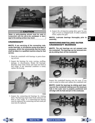
  • 1. 2-111 2 CM160 CRANKSHAFT NOTE: If any servicing of the connecting rods, center bearings, or oil-injection pump drive gear is necessary, Arctic Cat recommends that the crank- shaft be taken to a qualified machine shop for that service. 1. Wash the crankshaft with bearings in parts-clean- ing solvent. 2. Inspect the bearings for wear, scoring, scuffing, damage, or discoloration. Rotate the bearings. Bearings must rotate freely and must not bind or feel rough. If any abnormal condition is noted, replace the bearing. FC039 3. Inspect the connecting-rod bearings by rotating them. The bearings must rotate freely and must not bind or feel rough. If a connecting-rod bearing must be replaced, the connecting rod and crank pin must also be replaced. FC040 4. Inspect the oil-injection pump drive gear for any signs of worn or chipped teeth. If either condition exists, replace the gear. NOTE: Lubricate bearings thoroughly prior to assembly. REMOVING/INSTALLING OUTER CRANKSHAFT BEARINGS NOTE: The end bearings are not pressed onto the crankshaft. The bearings can be removed sim- ply by sliding them off the crankshaft. CM161 Inspect the crankshaft bearing area for wear. If any wear is noted on either end, replace the crankshaft end. NOTE: Install the bearings by sliding each bear- ing onto the crankshaft making sure the dowel-pin hole in the outer race is properly positioned and will align with its hole and pin in the crankcase. CM161 ! CAUTION Water or parts-cleaning solvent must be used in conjunction with the wet-or-dry sandpaper or dam- age to the sealing surface may result. Back to TOC Back to Section TOC NextBack
  • 2. 2-112 REED VALVE ASSEMBLY 1. Inspect the reed valves, stoppers, and valve blocks for cracks or any deterioration. CM162 2. Wash the reed valves, stopper, and cage assembly in parts-cleaning solvent and blow dry. 3. Inspect the reed stopper height. Using a caliper, measure the distance from the seat to the bottom outer tip edge of the stopper. Measurement must not exceed specifications. If measurement is not within specifications, either bend or replace the reed stopper. CM163 4. Inspect the reed-to-seat clearance. Using a feeler gauge, measure the clearance. Clearance must be less than 0.20 mm (0.008 in.). If clearance is not within specifications, replace the reed valve. 5. To assemble, place the reed valves on the cage with its clipped corner positioned to the lower right hand corner of the cage. Place the reed stop- per assembly into position and secure with the screws coated with red Loctite #271. CM164A Measuring Critical Components NOTE: Critical engine specifications charts can be found in Section 1 of this manual. CYLINDER HEAD VOLUME (Squish-Gap Method) To check the squish gap, a micrometer and two heavy pieces of solder will be needed. 1. Remove the spark plugs from the engine. 2. Simultaneously insert two pieces of solder down through the spark plug hole and push them up against the inner cylinder bore towards the MAG- side and PTO-side of the cylinder. 3. Pull the recoil rope and crank the engine over sev- eral times while the solder is being held firmly in place. 4. Remove both pieces of solder from the cylinder. Using the micrometer, measure the very end of the squeezed solder piece. Record the reading. NOTE: If the solder hasn’t been squeezed by the piston, a larger piece of solder must be used. Repeat procedure. 5. Using the opposite end of the solder pieces, insert them down through the spark plug hole towards the PTO-side and MAG-side of the cylinder. Push on the solder until they contact the inner cylinder bore. 6. Pull the recoil rope and crank the engine over sev- eral times. Remove both pieces of solder from the cylinder and measure the opposite squeezed ends with a micrometer. Record reading. NOTE: Measure from PTO to MAG-side of the pis- ton to accurately measure the squish gap. Never measure across piston, exhaust to carburetor side, as the piston will rock and the reading won’t be accurate. Readings may vary from side to side. Back to TOC Back to Section TOC NextBack
  • 3. 2-113 2 NOTE: Make sure the smaller reading is 1.5 mm (0.059 in.) or less for the 800 cc or 1.49 mm (0.058 in.) or less for the 1000 cc. CYLINDER TRUENESS 1. Measure each cylinder in the three locations from front to back and side to side for a total of six read- ings. FC044 2. The trueness (out-of-roundness) is the difference between the highest and lowest reading. Maxi- mum trueness (out-of-roundness) must not exceed 0.1 mm (0.004 in.). 0725-586 PISTON SKIRT/CYLINDER CLEARANCE 1. Measure each cylinder front to back about 2.5 cm (1 in.) from the bottom of each cylinder. 2. Measure the corresponding piston skirt diameter at a point 1 cm above the piston skirt at a right angle to the piston-pin bore. Subtract this measurement from the measurement in step 1. The difference (clearance) must be within 0.075-0.0105 mm (0.0029-0.0041 in.). AC091 PISTON-RING END GAP 1. Place each piston ring in the wear portion above the exhaust port of its respective cylinder. Use the pis- ton to position each ring squarely in each cylinder. 2. Using a feeler gauge, measure each piston-ring end gap. Acceptable ring end gap must be within 0.30-0.50 mm (0.012-0.0196 in.). FC045 PISTON PIN AND PISTON-PIN BORE 1. Measure the piston pin diameter at each end and in the center. Acceptable piston pin measurement must be within 21.995-22.000 mm (0.8659-0.8661 in.) for the 800 cc or 23.995-24.000 mm (0.9447- 0.9449 in.) for the 1000 cc. If any measurement varies by more than 0.02 mm (0.001 in.), the pis- ton pin and bearing must be replaced as a set. AN056 Back to TOC Back to Section TOC NextBack
  • 4. 2-114 2. Insert a snap gauge into each piston-pin bore; then remove the gauge and measure it with a micrometer. The diameter measurement must be within 22.002- 22.010 mm (0.8662-0.8665 in.) for the 800 cc or 24.002-24.010 mm (0.9450-0.9453 in.) for the 1000 cc. Take two measurements to ensure accuracy. AC092 CONNECTING-ROD SMALL END BORE 1. Insert a snap gauge into each connecting-rod small end bore; then remove the gauge and measure it with a micrometer. AN061 2. The diameter measurement must be within 27.003-27.011 mm (1.0631-1.0634 in.) for the 800 cc or 29.003-29.011 mm (1.1410-1.1420 in.) for the 1000 cc. CRANKSHAFT RUNOUT 0742-727 1. Using the V Blocks, support the crankshaft on the surface plate. NOTE: The V blocks should support the crank- shaft on the outer bearings. 2. Mount a dial indicator and base on the surface plate. Position the indicator contact point against the crankshaft location point A (PTO-end) from the crankshaft end. Zero the indicator and rotate the crankshaft slowly. Note the amount of crank- shaft runout (total indicator reading). NOTE: For runout location point specifications, see Crankshaft Runout Specifications in Section 1 of this manual. 3. Position the indicator contact point against the crankshaft location point B (MAG-end) from the crankshaft end. Zero the indicator and rotate the crankshaft slowly. Note the amount of crankshaft runout (total indicator reading). FC046 4. Position the indicator contact point against the crankshaft at location point C (center). Zero the indicator and rotate the crankshaft slowly. Note the amount of crankshaft runout (total indicator reading). 5. If runout exceeds 0.05 mm (0.002 in.) at any of the checkpoints, the crankshaft must be either straightened or replaced. Assembling Engine NOTE: The use of new gaskets and seals is rec- ommended when assembling the engine. NOTE: Before the engine is assembled, clean the threads of the cap screws and the threaded areas of the engine where loctite will be used. NOTE: When the use of a lubricant is indicated, use Arctic Cat Synthetic APV 2-Cycle Oil. 1. Apply a thin coat of grease to the inner seal lips of the water pump seal. Back to TOC Back to Section TOC NextBack
  • 5. 2-115 2 2. Using the seal driver, position the inner water pump shaft seal onto the seal driver and gently tap the seal down into position. NOTE: Grease must be applied to the lips of the inner seal before installation. MS986A NOTE: The seal must be installed with its spring side towards the crankshaft. 3. Install the snap ring securing the inner seal in the crankcase. MS415 4. Using the seal driver, carefully install the outer water pump seal. Gently tap the seal down into position until it seats itself against its flange. MS988 5. Apply a thin coat of grease to the sealing surface of the oil-injection pump/water pump driveshaft; then place the Oil Seal Protector Tool at the end of the shaft. Twist the driveshaft clockwise as it is pushed through the oil and water pump seals; then remove the tool. FS191 6. Position the shim on the oil-injection pump end of the driveshaft. CM159A 7. Secure the upper crankcase half upside-down on a suitable support; then install the C-ring (A), the four bearing retaining pins (B), and the two crank- case dowel pins (C). ! CAUTION Be very careful not to damage the seals when installing the oil pump driveshaft. Be certain to use the seal protector tool. Twist the driveshaft clock- wise as it enters the seal area and while it is being pushed through the seals. Back to TOC Back to Section TOC NextBack
  • 6. 2-116 CM165C 8. Place the crankshaft end bearings into position making sure the bearing retaining pin hole is posi- tioned inward. NOTE: The bearing retaining pin hole is the hole that does not go entirely through the bearing case. CM043A 9. Lubricate the inner lips of the crankshaft oil seals with grease; then slide the seals onto the crank- shaft making sure the spring side of each seal faces inward. NOTE: There is a MAG-side seal and a PTO-side seal. 10. Apply oil to the crankshaft bearings; then install the crankshaft into the upper crankcase half. Be sure the alignment hole in each bearing is posi- tioned over its respective dowel pin in the crank- case; then seat the crankshaft. CM045A NOTE: To check the bearing for proper position, place the point of a sharp tool into the dimple found in the bearing race. Strike the tool with the palm of the hand in either direction. If the bearing moves, it isn’t positioned correctly and must be rotated until it drops onto the dowel pin. 11. Position the two center seal rings with their end gaps 180° apart (up on one and down on the other); then apply a thin coat of High-Temp Seal- ant to the entire bottom half of the crankcase seal- ing surface. CM036A CM166 NOTE: Use only Arctic Cat High-Temp Sealant to seal the crankcase halves. 12. Assemble the crankcase halves making sure that the crankshaft gear and oil-injection pump drive- shaft gears mesh. Rotate the crankshaft one full turn to align the crankshaft gear and pump drive- shaft. 13. Install the crankcase cap screws securing the crankcase halves. 14. Tighten cap screws (1-10) in three steps to 31 ft-lb using the appropriate pattern shown. ! CAUTION If the bearings are not properly seated during assembly, the crankcase halves will not seal tightly and severe engine damage will result. Back to TOC Back to Section TOC NextBack
  • 7. 2-117 2 742-198A 742-197A 15. On the 800 cc, tighten cap screw (11) to 8 ft-lb; then turn the engine right-side up and tighten cap screws (12-15) in three steps to 25 ft-lb. 16. On the 1000 cc, tighten cap screws (11-13) in three steps to 25 ft-lb; then turn the engine right side up and tighten cap screw (14) to 8 ft-lb. NOTE: Secure the connecting rods with rubber hoses. 17. Install the oil-injection pump retainer with a new O-ring. FC082 18. With the new O-ring in place, install the oil-injec- tion pump making sure the pump shaft slot (A) and pump driven gear shaft (B) align. Secure with two screws (coated with blue Loctite #243). Tighten the two screws to 8 ft-lb. CM167A NOTE: For assembly purposes, always use a new O-ring lubricated with oil on the oil injection pump. 19. Install the oil-injection hoses and secure with the clamps; then place the lower union assembly into position and secure with new gaskets and union cap screw. Tighten to 54 in.-lb. CM153A 20. Secure the intake flanges, reed valve assemblies, and gaskets with cap screws; then in a crisscross pattern, tighten to 8 ft-lb. 21. Install the coolant temperature sensor and tighten securely; then secure the sensor wire to the sensor with a cable tie. 800 cc 1000 cc ! CAUTION Be sure the oil-injection pump/water pump drive- shaft is properly aligned with the slot of the oil-injec- tion pump. The pump will be damaged if these two components are not aligned. ! CAUTION Always use new gaskets and assure that a gasket is in place on each side of the union prior to securing the union cap screw to the crankcase. Back to TOC Back to Section TOC NextBack
  • 8. 2-118 CM172 22. Position the ceramic/rubber seal into the back side of the water pump impeller with the ceramic face of the seal directed out. CM168 23. Using both thumbs, press the seal into position making sure its marked side is positioned towards the rubber seal cup; then apply a thin coat of grease to the seal outer surface. CM169 24. Place the impeller into position and secure with a cap screw and washer. Be sure the rubber side of the washer is lubricated with a light coat of grease and directed toward the impeller. Apply blue Loc- tite #243 to the threads of the cap screw and tighten to 8 ft-lb. 25. Apply high-temperature sealant to the crankcase/ water pump cover seam; then install the dowel pins into the crankcase. CM171A NOTE: Sealant is only required on the crankcase seam. CM171B 26. Apply a thin film of low-temp grease to the water pump cover O-ring; then position the O-ring into the water pump cover. With the alignment pins in place, install the cover. Secure with seven screws using the pattern shown. Tighten to 8 ft-lb. 0742-257 27. With the bypass valve of the thermostat directed to the 12 o’clock position, install the thermostat and housing; then in a crisscross pattern, tighten the cap screws to 8 ft-lb.! CAUTION The rubber side of the washer, which secures the impeller, must be positioned toward the impeller. If installed incorrectly, a coolant leak will result. Back to TOC Back to Section TOC NextBack
  • 9. 2-119 2 CM157A CM155A 28. Install the dowel pins into the crankcase; then place the cylinder base gasket into position on the crankcase. 29. Install the piston rings on each piston so the letter on the top (inclined surface) of each ring faces the dome of the piston. 726-306A 30. Apply oil to the connecting-rod small end bear- ings; then install the small-end bearings. Install a washer on each side of the connecting rod. NOTE: The shoulder side of the washer must seat to the needle bearing. CM172A 31. Place each piston over the connecting rod so the indicator dot on each piston will point toward the intake/exhaust ports; then secure with an oiled pis- ton pin. NOTE: The indicator dot is found on the piston dome. CM173 32. Install the new circlips so the open end is directed either up or down. CM174 33. Rotate each piston ring until the ring ends are properly positioned on either side of the ring keeper; then apply oil to the piston assemblies and cylinder bores. Remove the rubber hoses from the connecting rods. ! CAUTION Incorrect installation of the piston rings will result in engine damage. ! CAUTION Make sure the circlips are firmly seated and the open end is directed either up or down before continuing with assembly. Back to TOC Back to Section TOC NextBack
  • 10. 2-120 34. In turn on each cylinder, place a piston holder (or suitable substitute) beneath the piston skirt and square the piston in respect to the crankcase; then using a ring compressor or the fingers, compress the rings and slide the cylinder over the piston. Remove the piston holder and seat the cylinder firmly onto the crankcase. NOTE: The cylinders should slide on easily. DO NOT force the pistons into the cylinders. CM148 35. Secure each cylinder by installing the four nuts and four new cap screws. DO NOT TIGHTEN AT THIS TIME. 36. Apply a thin coat of high-temperature silicone sealant to each exhaust port; then install the exhaust gaskets. 37. Apply a thin coat of high-temperature silicone sealant to the mating surfaces of the exhaust mani- fold; then install the exhaust manifold and secure with the eight nuts. Tighten the nuts using the pat- tern shown to 17 ft-lb. 0742-292 NOTE: Always use new cap screws when install- ing the cylinders. 38. Secure the cylinders (from step 35) by tightening the cylinder base nuts and cap screws to 42 ft-lb in three steps using the appropriate pattern shown. 0738-206 0738-220 39. Install the two cylinder O-rings on the top of each cylinder making sure they are correctly positioned in the grooves. FC077 NOTE: Lubricating the cylinder O-rings with a light coat of grease will help keep them seated in the grooves of the cylinder. 40. Place new O-rings onto each of the head cap screws. Place four of these cap screws (from oppo- site end of each other) into the cylinder head. Thread the spark plugs in part way; then while holding the head above the cylinder, carefully start and finger-tighten all four cap screws while observing the cylinder O-rings to make sure they remain in position. Slowly place the head into position on top of the O-rings. 800 cc 1000 cc Back to TOC Back to Section TOC NextBack