4 CH Analog Input Module -MOD-AI-4
•
0 gostou•18 visualizações

This document provides technical documentation for the MOD-AI-4 4 Channel Analog Input Module from Messung Systems Pvt. Ltd. It has 4 analog input channels that can accept either 0-10V, 4-20mA, or 0-20mA signals. The module supports Modbus RTU communication via an RS-485 interface and has DIP switches for configuration of the slave address, baud rate, and parity. It is powered by 24VDC and has LED indicators to show channel status and communication activity.

Recomendados
Recomendados
Mais conteúdo relacionado
Mais procurados
Mais procurados (18)
Semelhante a 4 CH Analog Input Module -MOD-AI-4
Semelhante a 4 CH Analog Input Module -MOD-AI-4 (20)
Mais de Messung Industrial Automation & Controls
Mais de Messung Industrial Automation & Controls (20)
Último
Último (20)
4 CH Analog Input Module -MOD-AI-4
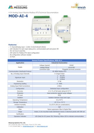
- 1. Messung Systems Pvt. Ltd. 501 Lunkad Sky Vista, Viman Nagar, Pune 411 014, India. T:+91 20 6649 2800 | e: info@messung.com | w: www.messung.com 4 CH Analog Input Module-Modbus RTUTechnical Documentation MOD-AI-4 Features: 4 ChannelAnalog input – (12bit- 0-10v/0-20mA/4-20mA) LED indication for each input status,error, communication port and power ON Din rail mount assembly. DIP switch for Modbus RTU slave configuration No configuration software needed CE Mark General Product Specifications: MOD-AI-4 Application Industrial Automation Supply Voltage (typical) 24VDC Voltage Range 18-30 VDC Connection type Pluggable terminal connector Communication Interface& Protocol RS 485& Modbus RTU No. of Analog Input Channels 4- Single Ended Signal-per input 1. 0V-10V 2. 4-20mA 3. 0-20mA Resolution 12 Bit Engineering Scalling 0 - 4095 Analog Input Field Connections 2-Wire Configuration Individual Input configuration Accuracy ± 0.1 % of full-scale rating @ 25 °C Protection Input protection against surge voltages IP Level IP20 Isolation Isolation between Input and Logic. Operating Temperature 0 to 70 °C Storage Temperature -25 °C to +75 °C Ambient Humidity 5 to 95 % RH (no condensation) Calibration Self Filter Noise suppression filter & Digital filter Usage Indoor, to be mounted inside distribution boxes or electrical panels with DIN rail Certification CE Operation Indicator LED (Red) for DC power ON, Flickering Yellow LED to indicate communication
- 2. Messung Systems Pvt. Ltd. 501 Lunkad Sky Vista, Viman Nagar, Pune 411 014, India. T:+91 20 6649 2800 | e: info@messung.com | w: www.messung.com WIRING DIAGRAM Modbus Configuration DIP switch access: Steps: 1. Open the upper facia plate of the module. 2. DIP switch S1 for address and DIP switch S2 for baud rate parity. 3. Adjust the DIP switchaccording to requirements. Refer below image. Modbus Communication Specifications: Protocol Slave Modbus RTU Baud Rate 9600,19200,57600,115200 Slave Address 1-31 Data bit 8 Stop bit 1 Parity None,Odd,Even Response time <100ms Termination Resistance 120ohm (Switchable) Control registers Holding Register& Input Register Distance Up to 1200m DIP Switch 2 Baud Rate configuration Baud Rate Pin 4 Pin 5 9600 OFF OFF 19200 OFF ON 57600 ON OFF 15200 ON ON Parity Configuration Parity Pin 3 Pin 2 NONE OFF OFF ODD OFF ON EVEN ON OFF Termination resistor configuration (120Ω) Termination Pin 1 ON ON OFF OFF DIP Switch 1 SlaveIDConfiguration Slave ID Pin 1 Pin 2 Pin 3 Pin 4 Pin 5 1 OFF OFF OFF OFF ON 2 OFF OFF OFF ON OFF 3 OFF OFF OFF ON ON 4 OFF OFF ON OFF OFF 5 OFF OFF ON OFF ON 6 OFF OFF ON ON OFF … … … … … … … … … … … … … … … … … … 31 ON ON ON ON ON
- 3. Messung Systems Pvt. Ltd. 501 Lunkad Sky Vista, Viman Nagar, Pune 411 014, India. T:+91 20 6649 2800 | e: info@messung.com | w: www.messung.com Dianostic: LED Color State Description Power Red ON Device is powered Communication Yellow BLINK Communication in progress (blink frequency depends to baud-rate) AI CH1 to AI CH4 Green ON If Input is present within range AI CH1 to AI CH4 Green Blink(1ms Interval) If Input is out of range Modbus Address Mapping: Modbus Registor Modbus Registor Description AI – CH1 Input Register – 30001 Channel 1 - Analog Input Count Voltage/Current AI – CH2 Input Register – 30002 Channel 2 - Analog Input Count Voltage/Current AI – CH3 Input Register – 30003 Channel 3 - Analog Input Count Voltage/Current AI – CH4 Input Register – 30004 Channel 4 - Analog Input Count Voltage/Current CH1 – Mode Selection Holding Register - 40002 0– Disable 1– Voltage – 0-10V (Default) 2– Current – 0-20mA 3– Current – 4-20mA CH2 – Mode Selection Holding Register – 40003 CH3 – Mode Selection Holding Register – 40004 CH4 – Mode Selection Holding Register - 40005 Filter Setting Holding Register – 40006 0 – 20SPS (Default) 1 – 60SPS SAFETY INSTRUCTIONS Installation should only be performed by qualifies professionals according to the laws and regulations. Do not connect the mains voltage nor any other external voltage to any point of the Modbus connector; it would represent a risk for the entire system. The facility must have enough insulation between the mains (or auxiliary) voltage and the Modbus or the wires of other accessories, in case of being installed. Keep the device away from water and do not cover it with clothes, paper or any other material while in use.