SlideShare uma empresa Scribd logo
1 de 59
Baixar para ler offline
HP Steam
HP Condensate Return
LP Steam
TANK HEATER
H
K
RECEIVER
PUMP
RECEIVER
Steam
Conservation
Guidelines for
Condensate
Drainage
Armstrong Steam and Condensate Group, 816 Maple St., Three Rivers, MI 49093 – USA Phone: (269) 273-1415 Fax: (269) 278-6555
armstronginternational.com
Table of Contents
3
Recommendation Charts and Instructions for Use ......................................................................................................................CG-2
Steam Tables .................................................................................................................................................................................CG-3
Steam...Basic Concepts................................................................................................................................................................CG-5
The Inverted Bucket Steam Trap..................................................................................................................................................CG-9
The Float & Thermostatic Steam Trap........................................................................................................................................CG-11
The Controlled Disc Steam Trap.................................................................................................................................................CG-12
The Thermostatic Steam Trap ....................................................................................................................................................CG-13
The Automatic Differential Condensate Controller.....................................................................................................................CG-14
Steam Trap Selection..................................................................................................................................................................CG-15
How to Trap:
Steam Distribution Systems........................................................................................................................................................CG-17
Steam Tracer Lines .....................................................................................................................................................................CG-21
Superheated Steam Lines...........................................................................................................................................................CG-23
Space Heating Equipment ..........................................................................................................................................................CG-25
Process Air Heaters.....................................................................................................................................................................CG-28
Shell and Tube Heat Exchangers...............................................................................................................................................CG-29
Evaporators..................................................................................................................................................................................CG-32
Jacketed Kettles ..........................................................................................................................................................................CG-35
Closed Stationary Steam Chamber Equipment .........................................................................................................................CG-37
Rotating Dryers Requiring Syphon Drainage.............................................................................................................................CG-39
Flash Tanks..................................................................................................................................................................................CG-41
Steam Absorption Machines .......................................................................................................................................................CG-43
Trap Selection and Safety Factors .............................................................................................................................................CG-44
Installation and Testing................................................................................................................................................................CG-45
Troubleshooting ...........................................................................................................................................................................CG-49
Pipe Sizing Steam Supply and Condensate Return Lines ........................................................................................................CG-50
Useful Engineering Tables...........................................................................................................................................................CG-53
Conversion Factors .....................................................................................................................................................................CG-54
Specific Heat - Specific Gravity...................................................................................................................................................CG-55
© 2011 Armstrong International, Inc.
13800 N101-Revised 2-11_838_Cons_Guide.qxd 2/8/11 10:13 AM Page 5
Bringing Energy Down to Earth
Say energy. Think environment. And vice versa.
Any company that is energy conscious is also environmentally
conscious. Less energy consumed means less waste, fewer
emissions and a healthier environment.
In short, bringing energy and environment together lowers
the cost industry must pay for both. By helping companies
manage energy, Armstrong products and services are also
helping to protect the environment.
Armstrong has been sharing know-how since we invented
the energy-efficient inverted bucket steam trap in 1911. In the
years since, customers’ savings have proven again and again
that knowledge not shared is energy wasted.
Armstrong’s developments and improvements in steam trap
design and function have led to countless savings in energy,
time and money. This section has grown out of our decades
of sharing and expanding what we’ve learned. It deals with the
operating principles of steam traps and outlines their specific
applications to a wide variety of products and industries.
You’ll find it a useful complement to other Armstrong literature
and the Armstrong Steam-A-ware™
software program for sizing
and selecting steam traps, pressure reducing valves and
water heaters, which can be requested through Armstrong’s
Web site, armstronginternational.com.
This section also includes Recommendation Charts that
summarize our findings on which type of trap will give
optimum performance in a given situation and why.
Armstrong Steam and Condensate Group, 816 Maple St., Three Rivers, MI 49093 – USA Phone: (269) 273-1415 Fax: (269) 278-6555
armstronginternational.com
IMPORTANT: This section is intended to summarize
general principles of installation and operation of steam
traps, as outlined above. Actual installation and operation
of steam trapping equipment should be performed
only by experienced personnel. Selection or installation
should always be accompanied by competent technical
assistance or advice. This data should never be used
as a substitute for such technical advice or assistance.
We encourage you to contact Armstrong or its local
representative for further details.
CG-1
13808 N101-Revised 2-11_838_Cons_Guide.qxd 2/3/11 12:24 PM Page CG1
Armstrong Steam and Condensate Group, 816 Maple St., Three Rivers, MI 49093 – USA Phone: (269) 273-1415 Fax: (269) 278-6555
armstronginternational.com
Instructions for Using the Recommendation Charts
A quick reference Recommendation Chart appears throughout
the “HOW TO TRAP” sections of this catalog, pages CG-17 to
CG-43.
A feature code system (ranging from A to Q) supplies you
with “at-a-glance” information.
The chart covers the type of steam traps and the major
advantages that Armstrong feels are superior for each
particular application.
For example, assume you are looking for information
concerning the proper trap to use on a gravity drained
jacketed kettle. You would:
1. Turn to the “How to Trap Jacketed Kettles” section,
pages CG-35 to CG-36, and look in the lower right-hand
corner of page CG-35. The Recommendation Chart
located there is reprinted below for your convenience.
(Each section has a Recommendation Chart.)
2. Find “Jacketed Kettles, Gravity Drain” in the first
column under “Equipment Being Trapped” and read
to the right for Armstrong’s “1st Choice and Feature
Code.” In this case, the first choice is an IBLV and
the feature code letters B, C, E, K, N are listed.
3. Now refer to Chart CG-2 below, titled “How Various
Types of Steam Traps Meet Specific Operating
Requirements” and read down the extreme left-hand
column to each of the letters B, C, E, K, N. The letter
“B,” for example, refers to the trap’s ability to provide
energy-conserving operation.
4. Follow the line for “B” to the right until you reach the
column that corresponds to our first choice, in this case
the inverted bucket. Based on tests and actual operating
conditions, the energy-conserving performance of the
inverted bucket steam trap has been rated “Excellent.”
Follow this same procedure for the remaining letters.
Abbreviations
IB Inverted Bucket Trap
IBLV Inverted Bucket Large Vent
BM Bimetallic Trap
F&T Float and Thermostatic Trap
CD Controlled Disc Trap
DC Automatic Differential
Condensate Controller
CV Check Valve
T Thermic Bucket
PRV Pressure Reducing Valve
(1) Drainage of condensate is continuous. Discharge is intermittent. (6) Cast iron traps not recommended.
(2) Can be continuous on low load. (7) In welded stainless steel construction – medium.
(3) Excellent when “secondary steam” is utilized. (8) Can fail closed due to dirt.
(4) Bimetallic and wafer traps – good. (9) Can fail either open or closed, depending upon the design
(5) Not recommended for low pressure operations. of the bellows.
CG2
Equipment Being
Trapped
1st Choice and
Feature Code
Alternate Choice
Jacketed Kettles
Gravity Drain
IBLV
B, C, E, K, N
F&T or Thermostatic
Jacketed Kettles
Syphon Drain
DC
B, C, E, G, H, K, N, P
IBLV
Chart CG-1. Recommendation Chart
(See chart below for “Feature Code” References.)
Feature
Code
Characteristic IB BM F&T Disc Thermostatic DC
A Method of Operation (1) Intermittent (2) Intermittent Continuous Intermittent (2) Intermittent Continuous
B Energy Conservation (Time in Service) Excellent Excellent Good Poor Fair (3) Excellent
C Resistance to Wear Excellent Excellent Good Poor Fair Excellent
D Corrosion Resistance Excellent Excellent Good Excellent Good Excellent
E Resistance to Hydraulic Shock Excellent Excellent Poor Excellent (4) Poor Excellent
F Vents Air and CO2 at Steam Temperature Yes No No No No Yes
G Ability to Vent Air at Very Low Pressure (1/4 psig) Poor (5) NR Excellent (5) NR Good Excellent
H Ability to Handle Start-Up Air Loads Fair Excellent Excellent Poor Excellent Excellent
I Operation Against Back Pressure Excellent Excellent Excellent Poor Excellent Excellent
J Resistance to Damage From Freezing (6) Good Good Poor Good Good Good
K Ability to Purge System Excellent Good Fair Excellent Good Excellent
L Performance on Very Light Loads Excellent Excellent Excellent Poor Excellent Excellent
M Responsiveness to Slugs of Condensate Immediate Delayed Immediate Delayed Delayed Immediate
N Ability to Handle Dirt Excellent Fair Poor Poor Fair Excellent
O Comparative Physical Size (7) Large Small Large Small Small Large
P Ability to Handle “Flash Steam” Fair Poor Poor Poor Poor Excellent
Q Mechanical Failure (Open or Closed) Open Open Closed (8) Open (9) Open
Chart CG-2. How Various Types of Steam Traps Meet Specific Operating Requirements
13808 N101-Revised 2-11_838_Cons_Guide.qxd 2/3/11 12:24 PM Page CG2
Armstrong Steam and Condensate Group, 816 Maple St., Three Rivers, MI 49093 – USA Phone: (269) 273-1415 Fax: (269) 278-6555
armstronginternational.com
What They Are…How to Use Them
The heat quantities and temperature/
pressure relationships referred to in
this section are taken from the Properties
of Saturated Steam table.
Definitions of Terms Used
Saturated Steam is pure steam at the
temperature that corresponds to the
boiling temperature of water at the
existing pressure.
Absolute and Gauge Pressures
Absolute pressure is pressure in
pounds per square inch (psia) above
a perfect vacuum. Gauge pressure is
pressure in pounds per square inch
above atmospheric pressure, which is
14.7 pounds per square inch absolute.
Gauge pressure (psig) plus 14.7 equals
absolute pressure. Or, absolute pressure
minus 14.7 equals gauge pressure.
Pressure/Temperature Relationship
(Columns 1, 2 and 3). For every
pressure of pure steam there is a
corresponding temperature. Example:
The temperature of 250 psig pure
steam is always 406°F.
Heat of Saturated Liquid (Column 4).
This is the amount of heat required
to raise the temperature of a pound
of water from 32°F to the boiling point
at the pressure and temperature
shown. It is expressed in British ther-
mal units (Btu).
Latent Heat or Heat of Vaporization
(Column 5). The amount of heat
(expressed in Btu) required to change
a pound of boiling water to a pound of
steam. This same amount of heat is
released when a pound of steam is
condensed back into a pound of water.
This heat quantity is different for every
pressure/temperature combination, as
shown in the steam table.
Total Heat of Steam (Column 6). The
sum of the Heat of the Liquid (Column
4) and Latent Heat (Column 5) in Btu.
It is the total heat in steam above 32°F.
Specific Volume of Liquid (Column 7).
The volume per unit of mass in cubic
feet per pound.
Specific Volume of Steam (Column 8).
The volume per unit of mass in cubic
feet per pound.
How the Table Is Used
In addition to determining pressure/
temperature relationships, you can
compute the amount of steam that will
be condensed by any heating unit of
known Btu output. Conversely, the
table can be used to determine Btu
output if steam condensing rate is
known. In the application portion of
this section, there are several references
to the use of the steam table.
Steam Tables
Table CG-1. Properties of Saturated Steam
(Abstracted from Keenan and Keyes, THERMODYNAMIC PROPERTIES OF STEAM,
by permission of John Wiley & Sons, Inc.)
Col. 1
Gauge
Pressure
Col. 2
Absolute
Pressure
(psia)
Col. 3
Steam
Temp.
(°F)
Col. 4
Heat of
Sat. Liquid
(Btu/lb)
Col. 5
Latent
Heat
(Btu/lb)
Col. 6
Total Heat
of Steam
(Btu/lb)
Col. 7
Specific
Volume of
Sat. Liquid
(cu ft/lb)
Col. 8
Specific
Volume of
Sat. Steam
(cu ft/lb)
29.743 0.08854 32.00 0.00 1075.8 1075.8 0.016022 3306.00
29.515 0.2 53.14 21.21 1063.8 1085.0 0.016027 1526.00
27.886 1.0 101.74 69.70 1036.3 1106.0 0.016136 333.60
19.742 5.0 162.24 130.13 1001.0 1131.0 0.016407 73.52
9.562 10.0 193.21 161.17 982.1 1143.3 0.016590 38.42
7.536 11.0 197.75 165.73 979.3 1145.0 0.016620 35.14
5.490 12.0 201.96 169.96 976.6 1146.6 0.016647 32.40
3.454 13.0 205.88 173.91 974.2 1148.1 0.016674 30.06
1.418 14.0 209.56 177.61 971.9 1149.5 0.016699 28.04
0.0 14.696 212.00 180.07 970.3 1150.4 0.016715 26.80
1.3 16.0 216.32 184.42 967.6 1152.0 0.016746 24.75
2.3 17.0 219.44 187.56 965.5 1153.1 0.016768 23.39
5.3 20.0 227.96 196.16 960.1 1156.3 0.016830 20.09
10.3 25.0 240.07 208.42 952.1 1160.6 0.016922 16.30
15.3 30.0 250.33 218.82 945.3 1164.1 0.017004 13.75
20.3 35.0 259.28 227.91 939.2 1167.1 0.017078 11.90
25.3 40.0 267.25 236.03 933.7 1169.7 0.017146 10.50
30.3 45.0 274.44 243.36 928.6 1172.0 0.017209 9.40
40.3 55.0 287.07 256.30 919.6 1175.9 0.017325 7.79
50.3 65.0 297.97 267.50 911.6 1179.1 0.017429 6.66
60.3 75.0 307.60 277.43 904.5 1181.9 0.017524 5.82
70.3 85.0 316.25 286.39 897.8 1184.2 0.017613 5.17
80.3 95.0 324.12 294.56 891.7 1186.2 0.017696 4.65
90.3 105.0 331.36 302.10 886.0 1188.1 0.017775 4.23
100.0 114.7 337.90 308.80 880.0 1188.8 0.017850 3.88
110.3 125.0 344.33 315.68 875.4 1191.1 0.017922 3.59
120.3 135.0 350.21 321.85 870.6 1192.4 0.017991 3.33
125.3 140.0 353.02 324.82 868.2 1193.0 0.018024 3.22
130.3 145.0 355.76 327.70 865.8 1193.5 0.018057 3.11
140.3 155.0 360.50 333.24 861.3 1194.6 0.018121 2.92
150.3 165.0 365.99 338.53 857.1 1195.6 0.018183 2.75
160.3 175.0 370.75 343.57 852.8 1196.5 0.018244 2.60
180.3 195.0 379.67 353.10 844.9 1198.0 0.018360 2.34
200.3 215.0 387.89 361.91 837.4 1199.3 0.018470 2.13
225.3 240.0 397.37 372.12 828.5 1200.6 0.018602 1.92
250.3 265.0 406.11 381.60 820.1 1201.7 0.018728 1.74
300.0 417.33 393.84 809.0 1202.8 0.018896 1.54
400.0 444.59 424.00 780.5 1204.5 0.019340 1.16
450.0 456.28 437.20 767.4 1204.6 0.019547 1.03
500.0 467.01 449.40 755.0 1204.4 0.019748 0.93
600.0 486.21 471.60 731.6 1203.2 0.02013 0.77
900.0 531.98 526.60 668.8 1195.4 0.02123 0.50
1200.0 567.22 571.70 611.7 1183.4 0.02232 0.36
1500.0 596.23 611.60 556.3 1167.9 0.02346 0.28
1700.0 613.15 636.30 519.6 1155.9 0.02428 0.24
2000.0 635.82 671.70 463.4 1135.1 0.02565 0.19
2500.0 668.13 730.60 360.5 1091.1 0.02860 0.13
2700.0 679.55 756.20 312.1 1068.3 0.03027 0.11
3206.2 705.40 902.70 0.0 902.7 0.05053 0.05
InchesofVacuumPSIG
CG3
8
13808 N101-Revised 2-11_838_Cons_Guide.qxd 2/3/11 12:24 PM Page CG3
400
300
200
100
0 100 200 300 400
PRESSURE AT WHICH CONDENSATE
IS FORMED—LBS/SQ IN
CUFTFLASHSTEAM
PERCUFTOFCONDENSATE
30
0
5
10
15
20
25
–20 300250200150100500
PERCENTAGEOFFLASHSTEAM
PSI FROM WHICH CONDENSATE IS DISCHARGED
CURVE
BACK PRESS.
LBS/SQ IN
A
B
C
D
E
F
G
10
5
0
10
20
30
40
–
–
B
C
D
E
F
A
G
Armstrong Steam and Condensate Group, 816 Maple St., Three Rivers, MI 49093 – USA Phone: (269) 273-1415 Fax: (269) 278-6555
armstronginternational.com
Steam Tables
Flash Steam (Secondary)
What is flash steam? When hot condensate or boiler
water, under pressure, is released to a lower pressure, part
of it is re-evaporated, becoming what is known as flash steam.
Why is it important? This flash steam is important because
it contains heat units that can be used for economical plant
operation—and which are otherwise wasted.
How is it formed? When water is heated at atmospheric
pressure, its temperature rises until it reaches 212°F,
the highest temperature at which water can exist at this
pressure. Additional heat does not raise the temperature,
but converts the water to steam.
The heat absorbed by the water in raising its temperature
to boiling point is called “sensible heat” or heat of saturated
liquid. The heat required to convert water at boiling point
to steam at the same temperature is called “latent heat.”
The unit of heat in common use is the Btu, which is the
amount of heat required to raise the temperature of one
pound of water 1°F at atmospheric pressure.
If water is heated under pressure, however, the boiling
point is higher than 212°F, so the sensible heat required
is greater. The higher the pressure, the higher the boiling
temperature and the higher the heat content. If pressure
is reduced, a certain amount of sensible heat is released.
This excess heat will be absorbed in the form of latent heat,
causing part of the water to “flash” into steam.
Condensate at steam temperature and under 100 psig
pressure has a heat content of 308.8 Btu per pound. (See
Column 4 in Steam Table.) If this condensate is discharged
to atmospheric pressure (0 psig), its heat content instantly
drops to 180 Btu per pound. The surplus of 128.8 Btu
re-evaporates or flashes a portion of the condensate.
The percentage that will flash to steam can be computed
using the formula:
% flash steam = x 100
SH = Sensible heat in the condensate at the higher
pressure before discharge.
SL = Sensible heat in the condensate at the lower
pressure to which discharge takes place.
H = Latent heat in the steam at the lower pressure
to which the condensate has been discharged.
% flash steam = x 100 =13.3%
Chart CG-3 shows the amount of secondary steam that
will be formed when discharging condensate to different
pressures. Other useful tables will be found on page
CG-53 (Useful Engineering Tables).
SH - SL
H
308.8 - 180
970.3
Chart CG-3.
Percentage of flash steam formed when discharging
condensate to reduced pressure.
Chart CG-4.
Volume of flash steam formed when one cubic foot of
condensate is discharged to atmospheric pressure.
CG4
9
13808 N101-Revised 2-11_838_Cons_Guide.qxd 2/3/11 12:24 PM Page CG4
+ 880 Btu=
1 lb water
at 70°F,
0 psig
1 lb water
at 338°F,
100 psig+ 270 Btu=
1 lb steam
at 338°F,
100 psig
Condensate Steam
1 lb water
at 70°F
1 lb water
at 212°F
1 lb steam
at 212°F
+ 970 Btu=
+ 142 Btu=
Steam…Basic Concepts
Steam is an invisible gas generated by adding heat
energy to water in a boiler. Enough energy must be added
to raise the temperature of the water to the boiling point.
Then additional energy—without any further increase in
temperature—changes the water to steam.
Steam is a very efficient and easily controlled heat transfer
medium. It is most often used for transporting energy from a
central location (the boiler) to any number of locations in the
plant where it is used to heat air, water or process applications.
As noted, additional Btu are required to make boiling water
change to steam. These Btu are not lost but stored in the
steam ready to be released to heat air, cook tomatoes,
press pants or dry a roll of paper.
The heat required to change boiling water into steam is
called the heat of vaporization or latent heat. The quantity
is different for every pressure/temperature combination,
as shown in the steam tables.
Steam at Work…
How the Heat of Steam Is Utilized
Heat flows from a higher temperature level to a lower
temperature level in a process known as heat transfer.
Starting in the combustion chamber of the boiler, heat
flows through the boiler tubes to the water. When the
higher pressure in the boiler pushes steam out, it heats
the pipes of the distribution system. Heat flows from the
steam through the walls of the pipes into the cooler
surrounding air. This heat transfer changes some of the
steam back into water. That’s why distribution lines are
usually insulated to minimize this wasteful and undesirable
heat transfer.
When steam reaches the heat exchangers in the system,
the story is different. Here the transfer of heat from the
steam is desirable. Heat flows to the air in an air heater,
to the water in a water heater or to food in a cooking kettle.
Nothing should interfere with this heat transfer.
Condensate Drainage…
Why It’s Necessary
Condensate is the by-product of heat transfer in a steam
system. It forms in the distribution system due to unavoidable
radiation. It also forms in heating and process equipment
as a result of desirable heat transfer from the steam to the
substance heated. Once the steam has condensed and
given up its valuable latent heat, the hot condensate must
be removed immediately. Although the available heat in a
pound of condensate is negligible as compared to a pound
of steam, condensate is still valuable hot water and should
be returned to the boiler.
Definitions
n The Btu. A Btu—British thermal unit—is the amount of
heat energy required to raise the temperature of one
pound of cold water by 1°F. Or, a Btu is the amount of
heat energy given off by one pound of water in cooling,
say, from 70°F to 69°F.
n Temperature. The degree of hotness with no implication
of the amount of heat energy available.
n Heat. A measure of energy available with no implication
of temperature. To illustrate, the one Btu that raises one
pound of water from 39°F to 40°F could come from the
surrounding air at a temperature of 70°F or from a flame
at a temperature of 1,000°F.
Armstrong Steam and Condensate Group, 816 Maple St., Three Rivers, MI 49093 – USA Phone: (269) 273-1415 Fax: (269) 278-6555
armstronginternational.com
Figure CG-1. These drawings show how much heat
is required to generate one pound of steam at
atmospheric pressure. Note that it takes 1 Btu for
every 1° increase in temperature up to the boiling
point, but that it takes more Btu to change water at
212°F to steam at 212°F.
Figure CG-2. These drawings show how much heat is required
to generate one pound of steam at 100 pounds per square inch
pressure. Note the extra heat and higher temperature required
to make water boil at 100 pounds pressure than at atmospheric
pressure. Note, too, the lesser amount of heat required to
change water to steam at the higher temperature.
CG5
13808 N101-Revised 2-11_838_Cons_Guide.qxd 2/3/11 12:24 PM Page CG5
100 psig
337.9°F
50.3 psig
297.97°F
Trap
Trap
Trap
Trap
Trap
Vent
PRV
Trap
A B
Armstrong Steam and Condensate Group, 816 Maple St., Three Rivers, MI 49093 – USA Phone: (269) 273-1415 Fax: (269) 278-6555
armstronginternational.com
Steam…Basic Concepts
The need to drain the distribution system. Condensate
lying in the bottom of steam lines can be the cause of one
kind of water hammer. Steam traveling at up to 100 miles
per hour makes “waves” as it passes over this condensate
Fig. CG-4). If enough condensate forms, high-speed steam
pushes it along, creating a dangerous slug that grows larger
and larger as it picks up liquid in front of it. Anything that
changes the direction—pipe fittings, regulating valves, tees,
elbows, blind flanges—can be destroyed. In addition to
damage from this “battering ram,” high-velocity water may
erode fittings by chipping away at metal surfaces.
The need to drain the heat transfer unit. When steam
comes in contact with condensate cooled below the temper-
ature of steam, it can produce another kind of water hammer
known as thermal shock. Steam occupies a much greater
volume than condensate, and when it collapses suddenly,
it can send shock waves throughout the system. This form
of water hammer can damage equipment, and it signals
that condensate is not being drained from the system.
Obviously, condensate in the heat transfer unit takes up
space and reduces the physical size and capacity of the
equipment. Removing it quickly keeps the unit full of steam
(Fig. CG-5). As steam condenses, it forms a film of water on
the inside of the heat exchanger. Non-condensable gases
do not change into liquid and flow away by gravity. Instead,
they accumulate as a thin film on the surface of the heat
exchanger—along with dirt and scale. All are potential
barriers to heat transfer (Fig. CG-3).
The need to remove air and CO2. Air is always present
during equipment start-up and in the boiler feedwater.
Feedwater may also contain dissolved carbonates, which
release carbon dioxide gas. The steam velocity pushes
the gases to the walls of the heat exchangers, where they
may block heat transfer. This compounds the condensate
drainage problem, because these gases must be removed
along with the condensate.
Figure CG-3. Potential barriers to heat transfer: steam heat
and temperature must penetrate these potential barriers to
do their work.
Figure CG-6. Note that heat radiation from the distribution system causes condensate to form and, therefore, requires steam
traps at natural low points or ahead of control valves. In the heat exchangers, traps perform the vital function of removing the
condensate before it becomes a barrier to heat transfer. Hot condensate is returned through the traps to the boiler for reuse.
Figure CG-5. Coil half full of condensate can’t work at
full capacity.
Figure CG-4. Condensate allowed to collect in pipes or
tubes is blown into waves by steam passing over it until it
blocks steam flow at point A. Condensate in area B causes
a pressure differential that allows steam pressure to push
the slug of condensate along like a battering ram.
CG6
11
Condensate Steam Vapor
13808 N101-Revised 2-11_838_Cons_Guide.qxd 2/3/11 12:24 PM Page CG6
450
425
400
375
350
325
300
275
250
225
200
150
100
300 250
200 150
100 75 50 25 0 100 90
80
70
60
50
40
30
20
10
0
100 90
80
70
60
50
40
30
20
10
0
PERCENT AIR BY VOLUME–%
PRESSURE–PSIG
300 250
200
150 100 75 50 25 0
0
450
425
400
375
350
325
300
275
250
225
200
150
100
0
TEMPERATUREF
Steam…Basic Concepts
Effect of Air on Steam Temperature
When air and other gases enter the steam system, they
consume part of the volume that steam would otherwise
occupy. The temperature of the air/steam mixture falls below
that of pure steam. Figure CG-7 explains the effect of air
in steam lines. Table CG-2 and Chart CG-5 show the vari-
ous temperature reductions caused by air at various per-
centages and pressures.
Effect of Air on Heat Transfer
The normal flow of steam toward the heat exchanger sur-
face carries air and other gases with it. Since they do not
condense and drain by gravity, these non-condensable
gases set up a barrier between the steam and the heat
exchanger surface. The excellent insulating properties of
air reduce heat transfer. In fact, under certain conditions
as little as 1/2 of 1% by volume of air in steam can reduce
heat transfer efficiency by 50% (Fig. CG-8).
When non-condensable gases (primarily air) continue to
accumulate and are not removed, they may gradually fill
the heat exchanger with gases and stop the flow of steam
altogether. The unit is then “air bound.”
Corrosion
Two primary causes of scale and corrosion are carbon
dioxide (CO2) and oxygen. CO2 enters the system as
carbonates dissolved in feedwater and, when mixed with
cooled condensate, creates carbonic acid. Extremely
corrosive, carbonic acid can eat through piping and heat
exchangers (Fig. CG-9). Oxygen enters the system as gas
dissolved in the cold feedwater. It aggravates the action of
carbonic acid, speeding corrosion and pitting iron and steel
surfaces (Fig. CG-10).
Eliminating the Undesirables
To summarize, traps must drain condensate because
it can reduce heat transfer and cause water hammer.
Traps should evacuate air and other non-condensable
gases because they can reduce heat transfer by reducing
steam temperature and insulating the system. They can
also foster destructive corrosion. It’s essential to remove
condensate, air and CO2 as quickly and completely as
possible. A steam trap, which is simply an automatic valve
that opens for condensate, air and CO2 and closes for
steam, does this job. For economic reasons, the steam trap
should do its work for long periods with minimum attention.
Armstrong Steam and Condensate Group, 816 Maple St., Three Rivers, MI 49093 – USA Phone: (269) 273-1415 Fax: (269) 278-6555
armstronginternational.com
Chart CG-5. Air Steam Mixture
Temperature reduction caused by various percentages of air at differing pres-
sures. This chart determines the percentage of air with known pressure and tem-
perature by determining the point of intersection between pressure, temperature
and percentage of air by volume. As an example, assume system pressure of 250
psig with a temperature at the heat exchanger of 375°F. From the chart, it is deter-
mined that there is 30% air by volume in the steam.
Figure CG-7. Chamber containing air
and steam delivers only the heat of the
partial pressure of the steam, not the
total pressure.
Steam chamber 100% steam
Total pressure 100 psia
Steam pressure 100 psia
Steam temperature 327.8°F
Steam chamber 90% steam and 10% air
Total pressure 100 psia
Steam pressure 90 psia
Steam temperature 320.3°F
Pressure
(psig)
Temp. of
Steam, No Air
Present (°F)
10% 20% 30%
10.3 240.1 234.3 228.0 220.9
25.3 267.3 261.0 254.1 246.4
50.3 298.0 291.0 283.5 275.1
75.3 320.3 312.9 304.8 295.9
100.3 338.1 330.3 321.8 312.4
Temp. of Steam Mixed With Various
Percentages of Air (by Volume) (°F)
Table CG-2. Temperature Reduction Caused by Air
CG7
12
13808 N101-Revised 2-11_838_Cons_Guide.qxd 2/3/11 12:24 PM Page CG7
Armstrong Steam and Condensate Group, 816 Maple St., Three Rivers, MI 49093 – USA Phone: (269) 273-1415 Fax: (269) 278-6555
armstronginternational.com
Steam…Basic Concepts
What the Steam Trap Must Do
The job of the steam trap is to get condensate, air and CO2
out of the system as quickly as they accumulate. In addition,
for overall efficiency and economy, the trap must also provide:
1. Minimal steam loss. Table CG-3 shows how costly
unattended steam leaks can be.
2. Long life and dependable service. Rapid wear of
parts quickly brings a trap to the point of undependability.
An efficient trap saves money by minimizing trap testing,
repair, cleaning, downtime and associated losses.
3. Corrosion resistance. Working trap parts should be
corrosion-resistant in order to combat the damaging
effects of acidic or oxygen-laden condensate.
4. Air venting. Air can be present in steam at any time
and especially on start-up. Air must be vented for
efficient heat transfer and to prevent system binding.
5. CO2 venting. Venting CO2 at steam temperature will
prevent the formation of carbonic acid. Therefore, the
steam trap must function at or near steam temperature
since CO2 dissolves in condensate that has cooled
below steam temperature.
6. Operation against back pressure. Pressurized return
lines can occur both by design and unintentionally. A steam
trap should be able to operate against the actual back
pressure in its return system.
7. Freedom from dirt problems. Dirt is an ever-present
concern since traps are located at low points in the
steam system. Condensate picks up dirt and scale in
the piping, and solids may carry over from the boiler.
Even particles passing through strainer screens are
erosive and, therefore, the steam trap must be able to
operate in the presence of dirt.
A trap delivering anything less than all these desirable
operating/design features will reduce the efficiency of the
system and increase costs. When a trap delivers all these
features the system can achieve:
1. Fast heat-up of heat transfer equipment
2. Maximum equipment temperature for enhanced steam
heat transfer
3. Maximum equipment capacity
4. Maximum fuel economy
5. Reduced labor per unit of output
6. Minimum maintenance and a long trouble-free service life
Sometimes an application may demand a trap without
these design features, but in the vast majority of applica-
tions the trap which meets all the requirements will deliver
the best results.
Figure CG-9. CO2 gas combines with
condensate allowed to cool below
steam temperature to form carbonic
acid, which corrodes pipes and heat
transfer units. Note groove eaten
away in the pipe illustrated.
Figure CG-8. Steam condensing in a
heat transfer unit moves air to the heat
transfer surface, where it collects or
“plates out” to form effective insulation.
Figure CG-10. Oxygen in the system
speeds corrosion (oxidation) of pipes,
causing pitting such as shown here.
Figs. CG-9 and CG-10 courtesy of Dearborn
Chemical Company.
Size of Orifice (in)
Lbs Steam Wasted
Per Month (USD) (USD)
Total Cost Per Month Total Cost Per Year
1/2 553,000 $5,530.00 $66,360.00
7/16 423,500 4,235.00 50,820.00
3/8 311,000 3,110.00 37,320.00
5/16 216,000 2,160.00 25,920.00
1/4 138,000 1,380.00 16,560.00
3/16 78,000 780.00 9,360.00
1/8 34,500 345.50 4,140.00
The steam loss values assume typical condensate load for drip trap applications.
Armstrong methodology for steam trap management and condensate return is sanctioned by the Clean Development
Mechanism of the United Nations Framework Convention on Climate Change.
Table CG-3. Cost of Various Sized Steam Leaks at 100 psi (69 bar)
(Assuming steam costs $10.00/1,000 lbs)
CG8
13
SteamCondensate
13800 N101-Revised 2-11_838_Cons_Guide.qxd 2/4/11 11:16 AM Page CG8
Valve
Closed
Valve Wide
Open
Flow Here
Picks Up Dirt
The Inverted Bucket Steam Trap
The Armstrong inverted submerged bucket steam trap is a
mechanical trap that operates on the difference in density
between steam and water. See Fig. CG-11. Steam entering
the inverted submerged bucket causes the bucket to float
and close the discharge valve. Condensate entering the
trap changes the bucket to a weight that sinks and opens
the trap valve to discharge the condensate. Unlike other
mechanical traps, the inverted bucket also vents air and
carbon dioxide continuously at steam temperature.
This simple principle of condensate removal was introduced
by Armstrong in 1911. Years of improvement in materials
and manufacturing have made today’s Armstrong inverted
bucket traps virtually unmatched in operating efficiency,
dependability and long life.
Long, Energy-Efficient Service Life
At the heart of the Armstrong inverted bucket trap is a unique
leverage system that multiplies the force provided by the
bucket to open the valve against pressure. There are no
fixed pivots to wear or create friction. It is designed to open
the discharge orifice for maximum capacity. Since the buck-
et is open at the bottom, it is resistant to damage from water
hammer. Wearing points are heavily reinforced for long life.
An Armstrong inverted bucket trap can continue to conserve
energy even in the presence of wear. Gradual wear slightly
increases the diameter of the seat and alters the shape and
diameter of the ball valve. But as this occurs, the ball merely
seats itself deeper—preserving a tight seal.
Reliable Operation
The Armstrong inverted bucket trap owes much of its reliability
to a design that makes it virtually free of dirt problems. Note
that the valve and seat are at the top of the trap. The larger
particles of dirt fall to the bottom, where they are pulverized
under the up-and-down action of the bucket. Since the valve
of an inverted bucket is either closed or fully open, there is
free passage of dirt particles. In addition, the swift flow of
condensate from under the bucket’s edge creates a unique
self-scrubbing action that sweeps dirt out of the trap. The
inverted bucket has only two moving parts—the valve lever
assembly and the bucket. That means no fixed points, no
complicated linkages—nothing to stick, bind or clog.
Corrosion-Resistant Parts
The valve and seat of Armstrong inverted bucket traps are
high chrome stainless steel, ground and lapped. All other
working parts are wear- and corrosion-resistant stainless steel.
Operation Against Back Pressure
High pressure in the discharge line simply reduces the
differential across the valve. As back pressure approaches
that of inlet pressure, discharge becomes continuous just
as it does on the very low pressure differentials.
Back pressure has no adverse effect on inverted bucket trap
operation other than capacity reduction caused by the low
differential. There is simply less force required by the bucket
to pull the valve open, cycling the trap.
Armstrong Steam and Condensate Group, 816 Maple St., Three Rivers, MI 49093 – USA Phone: (269) 273-1415 Fax: (269) 278-6555
armstronginternational.com
1. Steam trap is installed in drain line between steam-heated
unit and condensate return header. On start-up, bucket is
down and valve is wide open. As initial flood of condensate
enters the trap and flows under bottom of bucket, it fills trap
body and completely submerges bucket. Condensate then
discharges through wide-open valve to return header.
2. Steam also enters trap under bottom of bucket, where it
rises and collects at top, imparting buoyancy. Bucket then
rises and lifts valve toward its seat until valve is snapped tightly
shut. Air and carbon dioxide continually pass through bucket
vent and collect at top of trap. Any steam passing through
vent is condensed by radiation from trap.
Condensate Steam Air Flashing Condensate
Figure CG-11. Operation of the Inverted Bucket Steam Trap (at pressures close to maximum)
CG9
14
13808 N101-Revised 2-11_838_Cons_Guide.qxd 2/3/11 12:24 PM Page CG9
Valve Wide
Open
Self
Scrubbing
Flow
Valve
Closed
3. As the entering condensate starts to fill the bucket, the
bucket begins to exert a pull on the lever. As the condensate
continues to rise, more force is exerted until there is enough
to open the valve against the differential pressure.
4. As the valve starts to open, the pressure force across
the valve is reduced. The bucket then sinks rapidly and fully
opens the valve. Accumulated air is discharged first, followed
by condensate. The flow under the bottom of the bucket picks
up dirt and sweeps it out of the trap. Discharge continues
until more steam floats the bucket, and the cycle repeats.
Armstrong Steam and Condensate Group, 816 Maple St., Three Rivers, MI 49093 – USA Phone: (269) 273-1415 Fax: (269) 278-6555
armstronginternational.com
The Inverted Bucket Steam Trap
Types of Armstrong Inverted Bucket Traps
Available to Meet Specific Requirements
The availability of inverted bucket traps in different body
materials, piping configurations and other variables permits
flexibility in applying the right trap to meet specific needs.
See Table CG-4.
1. All-Stainless Steel Traps. Sealed, tamper-proof stain-
less steel bodies enable these traps to withstand freeze-
ups without damage. They may be installed on tracer
lines, outdoor drips and other services subject to freez-
ing. For pressures to 650 psig and temperatures to
800°F.
2. Cast Iron Traps. Standard inverted bucket traps for general
service at pressures to 250 psig and temperatures to 450°F.
Offered with side connections, side connections with integral
strainers and bottom inlet—top outlet connections.
3. Forged Steel Traps. Standard inverted bucket traps
for high pressure, high temperature services (including
superheated steam) to 2,700 psig at 1,050°F.
4. Cast Stainless Steel Traps. Standard inverted bucket
traps for high capacity, corrosive service. Repairable.
For pressures to 700 psig and temperatures to 506°F.
CG10
Cast Iron Stainless Steel Forged Steel Cast Steel Cast Stainless Steel
Connections 1/2" thru 2-1/2" 3/8" thru 1" 1/2" thru 2" 1/2" thru 1" 1/2" thru 2"
Type Connections Screwed Screwed, Socketweld
Screwed, Socketweld
or Flanged
Screwed, Socketweld
or Flanged
Screwed, Socketweld
or Flanged
Operating Pressure (psig) 0 thru 250 0 thru 650 0 thru 2,700 0 thru 600 0 thru 700
Capacity (lbs/hr) To 20,000 To 4,400 to 20,000 To 4,400 To 20,000
Table CG-4. Typical Design Parameters for Inverted Bucket Traps
15
Body and Cap Materials
13808 N101-Revised 2-11_838_Cons_Guide.qxd 2/3/11 12:24 PM Page CG10
The Float and Thermostatic Steam Trap
The float and thermostatic trap is a mechanical trap that
operates on both density and temperature principles. The
float valve operates on the density principle: A lever con-
nects the ball float to the valve and seat. Once condensate
reaches a certain level in the trap the float rises, opening
the orifice and draining condensate. A water seal formed
by the condensate prevents live steam loss.
Since the discharge valve is under water, it is not capable of
venting air and non-condensables. When the accumulation
of air and non-condensable gases causes a significant tem-
perature drop, a thermostatic air vent in the top of the trap
discharges it. The thermostatic vent opens at a temperature
a few degrees below saturation so it’s able to handle a large
volume of air—through an entirely separate orifice—but at a
slightly reduced temperature.
Armstrong F&T traps provide high air-venting capacity,
respond immediately to condensate and are suitable for
both industrial and HVAC applications.
Reliable Operation on Modulating Steam Pressure
Modulating steam pressure means that the pressure in the
heat exchange unit being drained can vary anywhere from
the maximum steam supply pressure down to vacuum under
certain conditions. Thus, under conditions of zero pressure,
only the force of gravity is available to push condensate
through a steam trap. Substantial amounts of air may also
be liberated under these conditions of low steam pressure.
The efficient operation of the F&T trap meets all of these
specialized requirements.
High Back Pressure Operation
Back pressure has no adverse effect on float and thermostatic
trap operation other than capacity reduction due to low
differential. The trap will not fail to close and will not blow
steam due to the high back pressure.
Armstrong Steam and Condensate Group, 816 Maple St., Three Rivers, MI 49093 – USA Phone: (269) 273-1415 Fax: (269) 278-6555
armstronginternational.com
Figure CG-12. Operation of the F&T Steam Trap
1. On start-up, low system pressure
forces air out through the thermostatic
air vent. A high condensate load
normally follows air venting and lifts
the float, which opens the main valve.
The remaining air continues to discharge
through the open vent.
2. When steam reaches the trap,
the thermostatic air vent closes in
response to higher temperature.
Condensate continues to flow through
the main valve, which is positioned by
the float to discharge condensate at
the same rate that it flows to the trap.
3. As air accumulates in the trap, the
temperature drops below that of saturated
steam. The balanced pressure thermostatic
air vent opens and discharges air.
NOTE: These operational schematics of the F&T trap do not represent actual trap configuration.
Condensate Steam Air
Cast Iron Cast Steel
Connections 1/2" thru 3" 1/2" thru 3"
Type Connections Screwed or Flanged
Screwed, Socketweld
or Flanged
Operating Pressure (psig) 0 thru 250 0 thru 465
Capacity (lbs/hr) To 208,000 To 280,000
Table CG-5. Typical Design Parameters for Float and Thermostatic Traps
CG11
16
Body and Cap Materials
13808 N101-Revised 2-11_838_Cons_Guide.qxd 2/3/11 12:24 PM Page CG11
Bimetallic steam traps have the ability to handle large start-up
loads. As the trap increases in temperature, its stacked nickel-chrome
bimetallic elements start to expand, allowing for tight shutoff as steam
reaches the trap, thus preventing steam loss. In addition to its light
weight and compact size, it offers resistance to water hammer.
Titanium valve and seat on high-pressure bimetallic traps ensure
extremely long service life in the harsh environment of superheated
steam systems.
Heating Chamber
Control Chamber
Control Disc
Inlet Passage
Outlet Passages
High Velocity Flow
Seat
Control
Chamber
Disc is held
against two
concentric
faces of seat
Armstrong Steam and Condensate Group, 816 Maple St., Three Rivers, MI 49093 – USA Phone: (269) 273-1415 Fax: (269) 278-6555
armstronginternational.com
The Controlled Disc Steam Trap
CG12
The controlled disc steam trap is a time-delayed device that operates
on the velocity principle. It contains only one moving part, the disc
itself. Because it is very lightweight and compact, the CD trap
meets the needs of many applications where space is limited. In
addition to the disc trap’s simplicity and small size, it also offers
advantages such as resistance to hydraulic shock, the complete
discharge of all condensate when open and intermittent operation
for a steady purging action.
Operation of controlled disc traps depends on the changes in
pressures in the chamber where the disc operates. The Armstrong
CD trap will be open as long as cold condensate is flowing. When
steam or flash steam reaches the inlet orifice, velocity of flow
increases, pulling the disc toward the seat. Increasing pressure in
the control chamber snaps the disc closed. The subsequent pressure
reduction, necessary for the trap to open, is controlled by the heating
chamber in the cap and a finite machined bleed groove in the disc.
Once the system is up to temperature, the bleed groove controls
the trap cycle rate.
Unique Heating Chamber
The unique heating chamber in Armstrong’s controlled disc traps
surrounds the disc body and control chamber. A controlled bleed
from the chamber to the trap outlet controls the cycle rate. That
means that the trap design—not ambient conditions—controls the
cycle rate. Without this controlling feature, rain, snow and cold
ambient conditions would upset the cycle rate of the trap.
1. On start-up, condensate and air entering the
trap pass through the heating chamber, around
the control chamber and through the inlet orifice.
This flow lifts the disc off the inlet orifice, and the
condensate flows through to the outlet passages.
2. Steam enters through the inlet passage and
flows under the control disc. The flow velocity across
the face of the control disc increases, creating a
low pressure that pulls the disc toward the seat.
3. The disc closes against two concentric faces
of the seat, closing off the inlet passage and also
trapping steam and condensate above the disc.
There is a controlled bleeding of steam from the
control chamber; flashing condensate helps main-
tain the pressure in the control chamber. When the
pressure above the disc is reduced, the incoming
pressure lifts the disc off the seat. If condensate is
present, it will be discharged, and the cycle repeats.
Figure CG-13. Design and Operation of Controlled Disc Traps Condensate Steam Air Condensate and Steam Mixture
Steel
Connections 3/8" thru 1"
Type Connections Screwed, Socketweld or Flanged
Operating Pressure (psig) 10 thru 600
Capacity (lbs/hr) To 2,850
Table CG-6. Typical Design Parameters for Controlled Disc Traps
1. On start-up, the trap is cold, so the elements
are flat and the valve is wide open, which results
in air and condensate being easily removed from
the system by working pressure.
2. With increasing temperature of the condensate,
the bimetallic elements will start to expand and flex.
3. When set temperature is reached, the force
of the elements is high enough to close the valve
completely against the system pressure working
on the valve.
The Bimetallic Steam Trap
Body and Cap Materials Carbon Steel Stainless Steel
Connection Sizes
Type Connections
Screwed,
Socketweld,
Flanged
Screwed, NPT,
BSPT, Socketweld,
Buttweld, Flanged
Operating psig 0 - 250 200 - 900
Cold Water Capacity lb/hr
Table CG-7. Typical Design Parameters for Bimetallic Traps
1/2", 3/4", 1"
up to 11,000
Figure CG-14. Design and Operation of Bimetallic Steam Traps Condensate Steam Air Flashing Steam
17
Body and Cap Materials
13808 N101-Revised 2-11_838_Cons_Guide.qxd 2/3/11 12:24 PM Page CG12
Alcohol
Vapor
Bulkhead
Wafer Alcohol
Liquid
Alcohol
Chamber
Armstrong Steam and Condensate Group, 816 Maple St., Three Rivers, MI 49093 – USA Phone: (269) 273-1415 Fax: (269) 278-6555
armstronginternational.com
The Thermostatic Steam Trap
Armstrong thermostatic steam traps are available with
balanced pressure bellows or wafer-type elements and
are constructed in a wide variety of materials, including
stainless steel, carbon steel and bronze. These traps are
used on applications with very light condensate loads.
Thermostatic Operation
Thermostatic steam traps operate on the difference in
temperature between steam and cooled condensate and
air. Steam increases the pressure inside the thermostatic
element, causing the trap to close. As condensate and
non-condensable gases back up in the cooling leg, the
temperature begins to drop, and the thermostatic element
contracts and opens the valve. The amount of condensate
backed up ahead of the trap depends on the load conditions,
steam pressure and size of the piping. It is important to note
that an accumulation of non-condensable gases can occur
behind the condensate backup.
NOTE: Thermostatic traps can also be used for venting air
from a steam system. When air collects, the temperature
drops and the thermostatic air vent automatically discharges the
air at slightly below steam temperature throughout the entire
operating pressure range.
Figure CG-15. Operation of the Thermostatic Steam Trap
1. On start-up, condensate and air
are pushed ahead of the steam directly
through the trap. The thermostatic
bellows element is fully contracted,
and the valve remains wide open until
steam approaches the trap.
2. As the temperature inside the trap
increases, it quickly heats the charged
bellows element, increasing the vapor
pressure inside. When pressure
inside the element becomes balanced
with system pressure in the trap body,
the spring effect of the bellows causes
the element to expand, closing the
valve. When temperature in the trap
drops a few degrees below saturated
steam temperature, imbalanced pres-
sure contracts the bellows, opening the
valve.
Figure CG-16.
Operation of Thermostatic Wafer
Balanced Pressure Thermostatic Wafer
operation is very similar to balanced
pressure bellows described in Fig. CG-
15. The wafer is partially filled with a
liquid. As the temperature inside the
trap increases, it heats the charged
wafer, increasing the vapor pressure
inside. When the pressure inside the
wafer exceeds the surrounding steam
pressure, the wafer membrane is
forced down on the valve seat, and the
trap is closed. A temperature drop
caused by condensate or non-con-
densable gases cools and reduces the
pressure inside the wafer, allowing the
wafer to uncover the seat.
Steam Condensate Condensate and Air
CG13
Body and Cap
Materials
Bronze Carbon
Steel
Stainless
Steel
Stainless
Steel
Bronze
Connections 1/2", 3/4" 1/2", 3/4" 1/4" thru 1" 1/2", 3/4" 1/2", 3/4", 1"
Type
Connections
Screwed,
Socketweld
Screwed,
Socketweld
Screwed,
Socketweld
NPT
Straight,
Angle
NPT
Straight,
Angle
Operating
Pressure
(psig)
0 - 300 0 - 50 0 - 400 0 - 600 0 - 65
Capacity
(lbs/hr) To 3,450 To 1,600 To 70 To 85 To 960
Table CG-8. Design Parameters for Thermostatic Traps
Balanced
Pressure Bellows
Balanced
Pressure Wafer
18
13808 N101-Revised 2-11_838_Cons_Guide.qxd 2/3/11 12:24 PM Page CG13
Condensate Return
DC
Condensate Return
To Secondary Steam Header
DC
Secondary Steam
Bucket
Inlet
Condensate Discharge Valve
Manual Metering Valve
Outlet
Condensate
Live and Flash Steam
Condensate and Secondary Steam
DottedLinesIndicateFieldPiping
Armstrong Steam and Condensate Group, 816 Maple St., Three Rivers, MI 49093 – USA Phone: (269) 273-1415 Fax: (269) 278-6555
armstronginternational.com
The Automatic Differential Condensate Controller
Armstrong automatic differential condensate controllers (DC)
are designed to function on applications where condensate
must be lifted from a drain point or in gravity drainage
applications where increased velocity will aid in drainage.
Lifting condensate from the drain point—often referred to
as syphon drainage—reduces the pressure of condensate,
causing a portion of it to flash into steam. Since ordinary
steam traps are unable to distinguish flash steam and live
steam, they close and impede drainage.
Increased velocity with gravity drainage will aid in drawing
the condensate and air to the DC. An internal steam by-pass
controlled by a manual metering valve causes this increased
velocity. Therefore, the condensate controller automatically
vents the by-pass or secondary steam. This is then collect-
ed for use in other heat exchangers or discharged to the
condensate return line.
Capacity considerations for draining equipment vary greatly
according to the application. However, a single condensate
controller provides sufficient capacity for most applications.
Condensate Controller Operation
Condensate, air and steam (live and flash) enter through the
controller inlet. At this point flash steam and air are automat-
ically separated from the condensate. Then they divert into
the integral by-pass at a controlled rate, forming secondary
steam (See Fig. CG-18).
The valve is adjustable so it matches the amount of flash
present under full capacity operation or to meet the velocity
requirements of the system. The condensate discharges
through a separate orifice controlled by the inverted bucket.
Because of the dual orifice design, there is a preset controlled
pressure differential for the secondary steam system, while
maximum pressure differential is available to discharge
the condensate.
Figure CG-17.
For the most efficient use of steam energy, Armstrong
recommends this piping arrangement when secondary
steam is collected and reused in heat transfer equipment.
Figure CG-18. Condensate Controller Operation
Piping arrangement when flash steam and non-condensables
are to be removed and discharged directly to the condensate
return line.
Cast Iron
Connections 1/2" thru 2"
Type Connections Screwed
Operating Pressure (psig) 0 thru 250
Capacity (lbs/hr) To 20,000
Table CG-9. Typical Design Parameters for the Automatic Differential
Condensate Controller
CG14
Steel
1" thru 2"
Screwed
0 thru 650
To 20,000
19
Body and Cap Materials
13808 N101-Revised 2-11_838_Cons_Guide.qxd 2/3/11 12:24 PM Page CG14
10"-12"
6"
Wrong Right
Trap Selection
To obtain the full benefits from the traps described in
the preceding section, it is essential to select traps of the
correct size and pressure for a given job and to install
and maintain them properly. One of the purposes of this
section is to supply the information to make that possible.
Actual installation and operation of steam trapping equipment
should be performed only by experienced personnel.
Selection or installation should always be accompanied
by competent technical assistance or advice. This section
should never be used as a substitute for such technical
advice or assistance. We encourage you to contact
Armstrong or its local representative for further details.
Basic Considerations
Unit trapping is the use of a separate steam trap on each
steam-condensing unit including, whenever possible, each
separate chest or coil of a single machine. The discussion
under the Short Circuiting heading explains the “why” of unit
trapping versus group trapping.
Rely on experience. Select traps with the aid of experience–
either yours, the know-how of your Armstrong Representative
or what others have learned in trapping similar equipment.
Do-it-yourself sizing. Do-it-yourself sizing is simple with the aid
of Steam-A-ware™
, Armstrong’s sizing and selection software
program, which can be downloaded at www.armstrong-intl.com.
Even without this computer program, you can easily size
steam traps when you know or can calculate:
1. Condensate loads in lbs/hr
2. The safety factor to use
3. Pressure differential
4. Maximum allowable pressure
1. Condensate load. Each “How To” portion of this
section contains formulas and useful information on
steam condensing rates and proper sizing procedures.
2. Safety factor or experience factor to use. Users have
found that they must generally use a safety factor in sizing
steam traps. For example, a coil condensing 500 lbs/hr
might require a trap that could handle up to 1,500 for
best overall performance. This 3:1 safety factor takes
care of varying condensate rates, occasional drops in
pressure differential and system design factors.
Safety factors will vary from a low of 1.5:1 to a high of
10:1. The safety factors in this book are based on years
of user experience.
Configuration affects safety factor. More important than
ordinary load and pressure changes is the design of the
steam-heated unit itself. Refer to Figs. CG-21, CG-22 and
CG-23 showing three condensing units each producing
500 pounds of condensate per hour, but with safety factors
of 2:1, 3:1 and 8:1.
Armstrong Steam and Condensate Group, 816 Maple St., Three Rivers, MI 49093 – USA Phone: (269) 273-1415 Fax: (269) 278-6555
armstronginternational.com
Figure CG-19. Two steam-consuming
units drained by a single trap, referred
to as group trapping, may result in
short circuiting.
Figure CG-20. Short circuiting is impos-
sible when each unit is drained by its
own trap. Higher efficiency is assured.
Short Circuiting
If a single trap connects more than one
drain point, condensate and air from one
or more of the units may fail to reach
the trap. Any difference in condensing
rates will result in a difference in the
steam pressure drop. A pressure drop
difference too small to register on a
pressure gauge is enough to let steam
from the higher pressure unit block the
flow of air or condensate from the lower
pressure unit. The net result is reduced
heating, output and fuel waste
(see Figs. CG-19 and CG-20).
Figure CG-21. Continuous coil, constant
pressure gravity flow to trap. 500 lbs/hr
of condensate from a single copper coil
at 30 psig. Gravity drainage to trap.
Volume of steam space very small.
2:1 safety factor.
Figure CG-22. Multiple pipes, modulated
pressure gravity flow to trap. 500 lbs/hr
of condensate from unit heater at 80
psig. Multiple tubes create minor short-
circuiting hazard. Use 3:1 safety factor
at 40 psig.
Figure CG-23. Large cylinder, syphon
drained. 500 lbs/hr from a 4' diameter,
10' long cylinder dryer with 115 cu ft
of space at 30 psig. The safety factor
is 3:1 with a DC and 8:1 with an IB.
Identical Condensing Rates, Identical Pressures With Differing Safety Factors
Condensate Steam
CG15
20
13808 N101-Revised 2-11_838_Cons_Guide.qxd 2/3/11 12:24 PM Page CG15
External
Check
Valve
Trap
Steam Main
Water Seal
Lift in feet
Pressure
drop over
water seal
to lift cold
condensate
Trap
4psi
3psi
2psi
1psi
1'
2'
3'
4'
5'
6'
7'
8'
9'
Trap
Inlet Pressure
or Maximum
Allowable Pressure
(MAP)
Differential Pressure or
Maximum Operating Pressure (MOP)
Back Pressure
or Vacuum
A B
Armstrong Steam and Condensate Group, 816 Maple St., Three Rivers, MI 49093 – USA Phone: (269) 273-1415 Fax: (269) 278-6555
armstronginternational.com
Trap Selection
Economical steam trap/orifice selection. While an ade-
quate safety factor is needed for best performance, too
large a factor causes problems. In addition to higher costs
for the trap and its installation, a needlessly oversized trap
wears out more quickly. And in the event of a trap failure, an
oversized trap loses more steam, which can cause water
hammer and high back pressure in the return system.
3. Pressure differential. Maximum differential is the
difference between boiler or steam main pressure or the
downstream pressure of a PRV and return line pressure.
See Fig. CG-24. The trap must be able to open against
this pressure differential.
NOTE: Because of flashing condensate in the return lines,
don’t assume a decrease in pressure differential due to
static head when elevating.
Operating differential. When the plant is operating at capaci-
ty, the steam pressure at the trap inlet may be lower than
steam main pressure. And the pressure in the condensate
return header may go above atmospheric.
If the operating differential is at least 80% of the maxi-
mum differential, it is safe to use maximum differential in
selecting traps.
Modulated control of the steam supply causes wide changes
in pressure differential. The pressure in the unit drained may
fall to atmospheric or even lower (vacuum). This does not
prevent condensate drainage if the installation practices in
this handbook are followed.
IMPORTANT: Be sure to read the discussion to the right,
which deals with less common but important reductions in
pressure differential.
4. Maximum allowable pressure. The trap must be able
to withstand the maximum allowable pressure of the
system or design pressure. It may not have to operate
at this pressure, but it must be able to contain it. As an
example, the maximum inlet pressure is 350 psig and
the return line pressure is 150 psig. This results in a
differential pressure of 200 psi; however, the trap must
be able to withstand 350 psig maximum allowable
pressure. See Fig. CG-24.
Factors Affecting Pressure Differential
Except for failures of pressure control valves, differential
pressure usually varies on the low side of the normal or
design value. Variations in either the inlet or discharge
pressure can cause this.
Inlet pressure can be reduced below its normal value by:
1. A modulating control valve or temperature regulator.
2. “Syphon drainage.” Every 2' of lift between the drainage
point and the trap reduces the inlet pressure
(and the differential) by one psi. See Fig. CG-25.
Discharge pressure can be increased above its normal
value by:
1. Pipe friction.
2. Other traps discharging into a return system of
limited capacity.
3. Elevating condensate. Every 2' of lift increases the
discharge pressure (and the differential) by one psi
when the discharge is only condensate. However, with
flash present, the extra back pressure could be reduced
to zero. See Fig. CG-26, noting the external check valve.
Figure CG-24. “A” minus “B” is
Pressure Differential: If “B” is back
pressure, subtract it from “A”. If “B”
is vacuum, add it to “A”.
Figure CG-25. Condensate from gravity
drain point is lifted to trap by a syphon.
Every 2' of lift reduces pressure differ-
ential by 1 psi. Note seal at low point
and the trap’s internal check valve to
prevent backflow.
Figure CG-26. When trap valve opens,
steam pressure will elevate conden-
sate. Every 2' of lift reduces pressure
differential by 1 psi.
Condensate Steam
CG16
21
13808 N101-Revised 2-11_838_Cons_Guide.qxd 2/3/11 12:24 PM Page CG16
Boiler #1
Header Level
Boiler #2
Trap
Trap
Typical Takeoffs
to System
Armstrong Steam and Condensate Group, 816 Maple St., Three Rivers, MI 49093 – USA Phone: (269) 273-1415 Fax: (269) 278-6555
armstronginternational.com
How to Trap Steam Distribution Systems
Steam distribution systems link boilers and the equipment
actually using steam, transporting it to any location in the
plant where its heat energy is needed.
The three primary components of steam distribution systems
are boiler headers, steam mains and branch lines. Each
fulfills certain requirements of the system and, together with
steam separators and steam traps, contributes to efficient
steam use.
Drip legs. Common to all steam distribution systems
is the need for drip legs at various intervals (Fig. CG-27).
These are provided to:
1. Let condensate escape by gravity from the
fast-moving steam.
2. Store the condensate until the pressure differential
can discharge it through the steam trap.
Boiler Headers
A boiler header is a specialized type of steam main that
can receive steam from one or more boilers. It is most often
a horizontal line which is fed from the top and in turn feeds
the steam mains. It is important to trap the boiler header
properly to assure that any carryover (boiler water and
solids) is removed before distribution into the system.
Steam traps that serve the header must be capable of
discharging large slugs of carryover as soon as they are
present. Resistance to hydraulic shock is also a consideration
in the selection of traps.
Trap selection and safety factor for boiler headers
(saturated steam only). A 1.5:1 safety factor is
recommended for virtually all boiler header applications.
The required trap capacity can be obtained by using
the following formula: Required Trap Capacity = Safety
Factor x Load Connected to Boiler(s) x Anticipated
Carryover (typically 10%).
EXAMPLE: What size steam trap will be required on
a connected load of 50,000 lbs/hr with an anticipated
carryover of 10%? Using the formula:
Required Trap Capacity = 1.5 x 50,000 x 0.10 = 7,500
lbs/hr.
The ability to respond immediately to slugs of condensate,
excellent resistance to hydraulic shock, dirt-handling ability
and efficient operation on very light loads are features that
make the inverted bucket the most suitable steam trap for
this application.
Installation. If steam flow through the header is in one
direction only, a single steam trap is sufficient at the down-
stream end. With a midpoint feed to the header (Fig. CG-28),
or a similar two-directional steam flow arrangement, each
end of the boiler header should be trapped.
Figure CG-28. Boiler Headers
Drip leg same as the header diameter up to 4..''
Above 4'', 1/2 header size, but never less than 4.''
Figure CG-27. Drip Leg Sizing
The properly sized drip leg
will capture condensate. Too
small a drip leg can actually
cause a venturi “piccolo”
effect where pressure drop
pulls condensate out of the
trap. See Table CG-13 on
page CG-19.
Equipment Being
Trapped
1st Choice and
Feature Code
Alternate Choice
Boiler Header
IBLV
*F&T
*On superheated steam never use an F&T type trap.
Always use an IB with internal check valve and burnished valve and seat.
Chart CG-6. Recommendation Chart
(See Page CG-2 for “Feature Code” References.)
M, E, L, N, B, Q
Equipment Being
Trapped
1st Choice, Feature Code
and Alternate Choice(s)
0 - 30
psig
Above
30 psig
B, M, N, L, F, E, C, D, Q *IB *IB
Alternate Choice F&T **F&T
B, C, D, E, F, L, M, N, Q, J *IB *IB
Alternate Choice
*Provide internal check valve when pressures fluctuate.
**Use IBLV above F&T pressure/temperature limitations.
Thermostatic or CD
NOTE: On superheated steam, use an IB with internal check valve and burnished valve
Steam Mains and
Branch Lines
Steam Mains and
Branch Lines
Non-freezing Conditions
Freezing Conditions
and seat.
22
CG-17
13808 N101-Revised 2-11_838_Cons_Guide.qxd 2/3/11 12:24 PM Page CG17
Armstrong Steam and Condensate Group, 816 Maple St., Three Rivers, MI 49093 – USA Phone: (269) 273-1415 Fax: (269) 278-6555
armstronginternational.com
Steam Mains
One of the most common uses of steam traps is the
trapping of steam mains. These lines need to be kept free of
air and condensate in order to keep steam-using equipment
operating properly. Inadequate trapping on steam mains
often leads to water hammer and slugs of condensate that
can damage control valves and other equipment.
There are two methods used for the warm-up of steam
mains—supervised and automatic. Supervised warm-up
is widely used for initial heating of large-diameter and/or
long mains. The suggested method is for drip valves to be
opened wide for free blow to the atmosphere before steam
is admitted to the main. These drip valves are not closed
until all or most of the warm-up condensate has been
discharged. Then the traps take over the job of removing
condensate that may form under operating conditions.
Warm-up of principal piping in a power plant will follow
much the same procedure.
Automatic warm-up is when the boiler is fired, allowing the
mains and some or all equipment to come up to pressure
and temperature without manual help or supervision.
CAUTION: Regardless of warm-up method, allow suffi-
cient time during the warm-up cycle to minimize thermal
stress and prevent any damage to the system.
Trap selection and safety factor for steam mains
(saturated steam only). Select trap to discharge conden-
sate produced by radiation losses at running load. Sizing
for start-up loads results in oversized traps, which may wear
prematurely. Size drip legs to collect condensate during
low-pressure, warm-up conditions. (See Table CG-13 on
page CG-19.) Condensate loads of insulated pipe can be
found in Table CG-10. All figures in the table assume the
insulation to be 75% effective. For pressures or pipe sizes
not included in the table, use the following formula:
C =
Where:
C = Condensate in lbs/hr-foot
A = External area of pipe in square feet
(Table CG-10, Col. 2)
U = Btu/sq ft/degree temperature
difference/hr from Chart CG-7 (page CG-19)
T1 = Steam temperature in °F
T2 = Air temperature in °F
E = 1 minus efficiency of insulation
(Example: 75% efficient insulation:
1 - .75 = .25 or E = .25)
H = Latent heat of steam
(See Steam Table on page CG-3)
How to Trap Steam Distribution Systems
A x U x (T1-T2)E
H
Table CG-11. The Warming-Up Load From 70°F, Schedule 40 Pipe
2 15 30 60 125 180 250
Pipe Size
(in)
wt of Pipe
Per ft (lbs)
1 1.69 .030 .037 .043 .051 .063 .071 .079
1-1/4 2.27 .040 .050 .057 .068 .085 .095 .106
1-1/2 2.72 .048 .059 .069 .082 .101 .114 .127
2 3.65 .065 .080 .092 .110 .136 .153 .171
2-1/2 5.79 .104 .126 .146 .174 .215 .262 .271
3 7.57 .133 .165 .190 .227 .282 .316 .354
3-1/2 9.11 .162 .198 .229 .273 .339 .381 .426
4 10.79 .190 .234 .271 .323 .400 .451 .505
5 14.62 .258 .352 .406 .439 .544 .612 .684
6 18.97 .335 .413 .476 .569 .705 .795 .882
8 28.55 .504 .620 .720 .860 1.060 1.190 1.340
10 40.48 .714 .880 1.020 1.210 1.500 1.690 1.890
12 53.60 .945 1.170 1.350 1.610 2.000 2.240 2.510
14 63.00 1.110 1.370 1.580 1.890 2.340 2.640 2.940
16 83.00 1.460 1.810 2.080 2.490 3.080 3.470 3.880
18 105.00 1.850 2.280 2.630 3.150 3.900 4.400 4.900
20 123.00 2.170 2.680 3.080 3.690 4.570 5.150 5.750
24 171.00 3.020 3.720 4.290 5.130 6.350 7.150 8.000
Steam Pressure, psig
Pounds of Water Per Lineal Foot
Table CG-10. Condensation in Insulated Pipes Carrying Saturated Steam
in Quiet Air at 70°F (Insulation assumed to be 75% efficient.)
15 30 60 125 180 250 450 600 900
Pipe Size
(in)
sq ft Per
Lineal ft
1 .344 .05 .06 .07 .10 .12 .14 .186 .221 .289
1-1/4 .434 .06 .07 .09 .12 .14 .17 .231 .273 .359
1-1/2 .497 .07 .08 .10 .14 .16 .19 .261 .310 .406
2 .622 .08 .10 .13 .17 .20 .23 .320 .379 .498
2-1/2 .753 .10 .12 .15 .20 .24 .28 .384 .454 .596
3 .916 .12 .14 .18 .24 .28 .33 .460 .546 .714
3-1/2 1.047 .13 .16 .20 .27 .32 .38 .520 .617 .807
4 1.178 .15 .18 .22 .30 .36 .43 .578 .686 .897
5 1.456 .18 .22 .27 .37 .44 .51 .698 .826 1.078
6 1.735 .20 .25 .32 .44 .51 .59 .809 .959 1.253
8 2.260 .27 .32 .41 .55 .66 .76 1.051 1.244 1.628
10 2.810 .32 .39 .51 .68 .80 .94 1.301 1.542 2.019
12 3.340 .38 .46 .58 .80 .92 1.11 1.539 1.821 2.393
14 3.670 .42 .51 .65 .87 1.03 1.21 1.688 1.999 2.624
16 4.200 .47 .57 .74 .99 1.19 1.38 1.927 2.281 2.997
18 4.710 .53 .64 .85 1.11 1.31 1.53 2.151 2.550 3.351
20 5.250 .58 .71 .91 1.23 1.45 1.70 2.387 2.830 3.725
24 6.280 .68 .84 1.09 1.45 1.71 2.03 2.833 3.364 4.434
Pounds of Condensate Per Hour Per Lineal Foot
Pressure, psig
Table CG-12. Pipe Weights Per Foot in Pounds
Pipe Size (in) Schedule 40 Schedule 80 Schedule 160 XX Strong
1 1.69 2.17 2.85 3.66
1-1/4 2.27 3.00 3.76 5.21
1-1/2 2.72 3.63 4.86 6.41
2 3.65 5.02 7.45 9.03
2-1/2 5.79 7.66 10.01 13.69
3 7.57 10.25 14.32 18.58
3-1/2 9.11 12.51 — 22.85
4 10.79 14.98 22.60 27.54
5 14.62 20.78 32.96 38.55
6 18.97 28.57 45.30 53.16
8 28.55 43.39 74.70 72.42
10 40.48 54.74 116.00 —
12 53.60 88.60 161.00 —
14 63.00 107.00 190.00 —
16 83.00 137.00 245.00 —
18 105.00 171.00 309.00 —
20 123.00 209.00 379.00 —
24 171.00 297.00 542.00 —
CG18
23
13808 N101-Revised 2-11_838_Cons_Guide.qxd 2/3/11 12:24 PM Page CG18
11
10
9
8
7
6
5
4.5
4.0
3.5
3.3
3.0
2.8
2.6
2.5
2.4
2.3
2.2
2.15
PSIG
11
10
9
8
7
6
5
4.5
4.0
3.5
3.3
3.0
2.8
2.6
2.5
2.4
2.3
2.2
2.15
2.10
5.3
10.3
15.3
25.3
50.3
75.3
100.3
150.3
250.3
450.3
600.3
900.3
1500.3
2400.3
PRESSURE IN LBS PER SQUARE INCH
BTUPERSQFTPERHOURPERFTEMPERATUREDIFFERENCE
TEMPERATURE DIFFERENCE
150 160 180 200 240 300 400 500 700 900 1050
1"
2"2"
3"
5"5"
2"
5"
6"
10"
FLAT SURFACES
How to Trap Steam Distribution Systems
For traps installed between the boiler and the end of the
steam main, apply a 2:1 safety factor. Apply a 3:1 safety
factor for traps installed at the end of the main or ahead of
reducing and shutoff valves that are closed part of the time.
The inverted bucket trap is recommended because it can
handle dirt and slugs of condensate and resists hydraulic
shock. In addition, should an inverted bucket fail, it usually
does so in the open position.
Installation. Both methods of warm-up use drip legs and
traps at all low spots or natural drainage points such as:
Ahead of risers
End of mains
Ahead of expansion joints or bends
Ahead of valves or regulators
Install drip legs and drain traps even where there are no
natural drainage points (See Figs. CG-29, CG-30 and CG-31).
These should normally be installed at intervals of about 300'
and never longer than 500'.
On a supervised warm-up, make drip leg length at least
1-1/2 times the diameter of the main, but never less than
10". Make drip legs on automatic warm-ups a minimum of
28" in length. For both methods, it is a good practice to use
a drip leg the same diameter as the main up to 4" pipe size
and at least 1/2 of the diameter of the main above that, but
never less than 4". See Table CG-13.
Armstrong Steam and Condensate Group, 816 Maple St., Three Rivers, MI 49093 – USA Phone: (269) 273-1415 Fax: (269) 278-6555
armstronginternational.com
Figure CG-29.
Trap draining strainer ahead of PRV.
Figure CG-30.
Trap draining drip leg on main.
Figure CG-31.
Trap draining drip leg at riser. Distance
“H” in inches ÷ 28 = psi static head for
forcing water through the trap.
Steam Mains
D
M
H
Drip leg same
as the header
diameter up to
4''. Above 4'',
1/2 header size,
but never less
than 4''.
Chart CG-8. Recommendation Chart
(See Page CG-2 for “Feature Code” References.)
Equipment Being
Trapped
1st Choice and
Feature Code
Alternate Choice
Steam Separator
IBLV
*DC
*DC is 1st choice where steam quality is 90% or less.
M D
Supervised
Warm-Up
Automatic
Warm-Up
1/2 1/2 10 28
3/4 3/4 10 28
1 1 10 28
2 2 10 28
3 3 10 28
4 4 10 28
6 4 10 28
8 4 12 28
10 6 15 28
12 6 18 28
14 8 21 28
16 8 24 28
18 10 27 28
20 10 30 30
24 12 36 36
Drip Leg Length Min. (in)
Steam Main
Size (in)
Drip Leg
Diameter (in)
H
Table CG-13. Recommended Steam Main and Branch Line Drip Leg Sizing
Chart CG-7. Btu Heat Loss Curves
CG19
H
B, M, L, E, F, N, Q
M
24
13808 N101-Revised 2-11_838_Cons_Guide.qxd 2/3/11 12:24 PM Page CG19
Armstrong Steam and Condensate Group, 816 Maple St., Three Rivers, MI 49093 – USA Phone: (269) 273-1415 Fax: (269) 278-6555
armstronginternational.com
How to Trap Steam Distribution Systems
Branch Lines
Branch lines are take-offs from the steam mains supplying
specific pieces of steam-using equipment. The entire system
must be designed and hooked up to prevent accumulation
of condensate at any point.
Trap selection and safety factor for branch lines. The
formula for computing condensate load is the same as
that used for steam mains. Branch lines also have a recom-
mended safety factor of 3:1.
Installation. Recommended piping from the main to the
control is shown in Fig. CG-32 for runouts under 10' and
Fig. CG-33 for runouts over 10'. See Fig. CG-34 for piping
when control valve must be below the main.
Install a full pipe-size strainer ahead of each control valve
as well as ahead of the PRV, if used. Provide blowdown
valves, preferably with IB traps. A few days after starting
the system, examine the strainer screens to see if cleaning
is necessary.
Separators
Steam separators are designed to remove any condensate
that forms within steam distribution systems. They are most
often used ahead of equipment where especially dry steam
is essential. They are also common on secondary steam
lines, which by their very nature have a large percentage
of entrained condensate.
Important factors in trap selection for separators are the
ability to handle slugs of condensate, provide good resist-
ance to hydraulic shock and operate on light loads.
Trap selection and safety factors for separators. Apply
a 3:1 safety factor in all cases, even though different types
of traps are recommended, depending on condensate and
pressure levels.
Use the following formula to obtain the required trap capacity:
Required trap capacity in lbs/hr = safety factor x steam flow
rate in lbs/hr x anticipated percent of condensate (typically
10% to 20%).
EXAMPLE: What size steam trap will be required on a flow
rate of 10,000 lbs/hr? Using the formula:
Required trap capacity =
3 x 10,000 x 0.10 = 3,000 lbs/hr.
The inverted bucket trap with large vent is recommended
for separators. When dirt and hydraulic shock are not
significant problems, an F&T type trap is an acceptable
alternative.
An automatic differential condensate controller may be pre-
ferred in many cases. It combines the best features of both
of the above and is recommended for large condensate
loads that exceed the separating capability of the separator.
Installation
Connect traps to the separator drain line 10" to 12" below
the separator with the drain pipe running the full size of the
drain connection down to the trap take-off (Fig. CG-35). The
drain pipe and dirt pocket should be the same size as the
drain connection.
Figure CG-33. Piping for runout greater
than 10'. Drip leg and trap required
ahead of control valve. Strainer ahead
of control valve can serve as drip
leg if blowdown connection runs to
an inverted bucket trap. This will also
minimize the strainer cleaning problem.
Trap should be equipped with an internal
check valve or a swing check installed
ahead of the trap.
Figure CG-34. Regardless of the length
of the runout, a drip leg and trap are
required ahead of the control valve
located below steam supply. If coil is
above control valve, a trap should also
be installed at downstream side of
control valve.
Figure CG-35. Drain downstream side
of separator. Full-size drip leg and dirt
pocket are required to ensure positive
and fast flow of condensate to the
trap.
Figure CG-32. Piping for runout less than 10 ft. No trap
required unless pitch back to supply header is less than
1/2'' per ft.
10' or Less
Pitch 1/2'' per 1 ft
Runout Oversized
One Pipe Size
or More
CG20
More than
10'
Pitch Down 1/2''
per 10 ft
Steam
Separator
Shutoff Valve 10''-12''
IBLV or
DC
Steam Separator
Branch Lines
6''
25
13808 N101-Revised 2-11_838_Cons_Guide.qxd 2/3/11 12:24 PM Page CG20
Armstrong Steam and Condensate Group, 816 Maple St., Three Rivers, MI 49093 – USA Phone: (269) 273-1415 Fax: (269) 278-6555
armstronginternational.com
How to Trap Steam Tracer Lines
Steam tracer lines are designed to maintain the fluid in a
primary pipe at a certain uniform temperature. In most
cases, these tracer lines are used outdoors, which makes
ambient weather conditions a critical consideration.
The primary purpose of steam traps on tracer lines is to
retain the steam until its latent heat is fully utilized and then
discharge the condensate and non-condensable gases. As
is true with any piece of heat transfer equipment, each tracer
line should have its own trap. Even though multiple tracer
lines may be installed on the same primary fluid line, unit
trapping is required to prevent short circuiting.
See page CG-15.
In selecting and sizing steam traps, it’s important to consider
their compatibility with the objectives of the system, as
traps must:
1. Conserve energy by operating reliably over a long period
of time.
2. Provide abrupt periodic discharge in order to purge the
condensate and air from the line.
3. Operate under light load conditions.
4. Resist damage from freezing if the steam is shut off.
The cost of steam makes wasteful tracer lines an exorbitant
overhead no industry can afford.
Trap Selection for Steam Tracer Lines.
The condensate load to be handled on a steam tracer line
can be determined from the heat loss from the product pipe
by using this formula:
Q =
Where:
Q = Condensate load, lbs/hr
L = Length of product pipe between tracer
line traps in ft
U = Heat transfer factor in Btu/sq ft/°F/hr
(from Chart CG-7, page CG-19)
∆T = Temperature differential in °F
E = 1 minus efficiency of insulation
(example: 75% efficient insulation or
1 - .75 = .25 or E = .25)
S = Lineal feet of pipe line per sq ft of surface
(from Table CG-29, page CG-53)
H = Latent heat of steam in Btu/lb
(from Steam Table, page CG-3)
L x U x ∆T x E
S x H
Figure CG-36. Figure CG-37.
Typical Tracer Installation
Freeze-
Protection Drain
Check
Valve
Chart CG-9. Recommendation Chart
(See Page CG-2 for “Feature Code” References.)
Equipment Being
Trapped
1st Choice and
Feature Code
Alternate Choice
Tracer Lines
*IB
A, B, C, L, J, N, I, K
Thermostatic or CD
*Select a 5/64" steam trap orifice to conserve energy and avoid plugging with dirt
and scale.
Pipe Size (in) Iron Pipe
Copper or
Brass Pipe
1/2 4.55 7.63
3/4 3.64 5.09
1 2.90 3.82
1-1/4 2.30 3.05
1-1/2 2.01 2.55
2 1.61 1.91
2-1/2 1.33 1.52
3 1.09 1.27
4 .848 .954
Table CG-14. Pipe Size Conversion Table (Divide lineal feet of pipe by
factor given for size and type of pipe to get square feet of surface.)
CG21
26
13808 N101-Revised 2-11_838_Cons_Guide.qxd 2/3/11 12:24 PM Page CG21
11
10
9
8
7
6
5
4.5
4.0
3.5
3.3
3.0
2.8
2.6
2.5
2.4
2.3
2.2
2.15
PSIG
11
10
9
8
7
6
5
4.5
4.0
3.5
3.3
3.0
2.8
2.6
2.5
2.4
2.3
2.2
2.15
2.10
5.3
10.3
15.3
25.3
50.3
75.3
100.3
150.3
250.3
450.3
600.3
900.3
1500.3
2400.3
PRESSURE IN LBS PER SQUARE INCH
BTUPERSQFTPERHOURPERFTEMPERATUREDIFFERENCE
TEMPERATURE DIFFERENCE
150 160 180 200 240 300 400 500 700 900 1050
1"
2"2"
3"
5"5"
2"
5"
6"
10"
FLAT SURFACES
Armstrong Steam and Condensate Group, 816 Maple St., Three Rivers, MI 49093 – USA Phone: (269) 273-1415 Fax: (269) 278-6555
armstronginternational.com
How to Trap Steam Tracer Lines
EXAMPLE: Three tracer lines at 100 psig steam pressure
are used on a 20" diameter, 100' long insulated pipe to
maintain a temperature of 190°F with an outdoor design
temperature of -10°F. Assume further that the pipe insulation
is 75% efficient. What is the condensate load?
Using the formula:
Now divide by three in order to get the load per
tracer line — 24 lbs/hr.
On most tracer line applications, the flow to the steam trap
is surprisingly low; therefore, the smallest trap is normally
adequate. Based on its ability to conserve energy by operat-
ing reliably over a long period of time, handle light loads,
resist freezing and purge the system, an inverted bucket
trap is recommended for tracer line service.
Safety factor. Use a 2:1 safety factor whether exposure
to ambient weather conditions is involved or not. Do not
oversize steam traps or tracer lines. Select a 5/64" steam
trap orifice to conserve energy and avoid plugging
with dirt and scale.
Installation
Install distribution or supply lines at a height above the
product lines requiring steam tracing. For the efficient
drainage of condensate and purging of non-condensables,
pitch tracer lines for gravity drainage and trap all low spots.
This will also help avoid tracer line freezing.
(See Figs. CG-36, CG-37 and CG-38.)
To conserve energy, return condensate to the boiler.
Use vacuum breakers immediately ahead of the traps
to ensure drainage on shutdown on gravity drain systems.
Freeze-protection drains on trap discharge headers are
suggested where freezing conditions prevail.
100 ft x 2.44 Btu/sq ft -°F - hr x 200°F x .25
0.191 lin ft/sq ft x 800 Btu/lb
Q = = 72 lbs/hr
Figure CG-38. Typical Tracer Installation Chart CG-10. Btu Heat Loss Curves
Unit heat loss per sq ft of surface of uninsulated pipe of
various diameters (also flat surface) in quiet air at 75°F for
various saturated steam pressures or temperature differences.
Vacuum
Breaker
Freeze-Protection Drain
CG22
27
13808 N101-Revised 2-11_838_Cons_Guide.qxd 2/3/11 12:24 PM Page CG22
Condenser
Fuel
Superheater
Cool Water
Turbine
Generator
Steam
(Low Pressure)
Pump
Pump
Cool Water
(From Tower or
Lake/River)
Vapor
Air
Inlet
Superheated Steam
(High Pressure)
Low-Temperature
Water
(High Pressure)
Stack
Gases Outlet
Warm
Air
Preheated
Air
Hot Water
How to Trap Superheated Steam Lines
At first glance, this may seem confusing due to the idea
that superheated steam produces no condensate; therefore,
the steam lines carrying superheated steam should not have
any condensate in them. This is true once the system is up
to temperature and pressure, but condensate removal is
necessary up to this point. This section will explain what
superheated steam is and the applications for its use.
The specific heat of any substance (using Btu standards)
is the quantity of heat required to raise the temperature of
1 pound by 1 degree F. With this definition, the specific heat
of water is 1, and the specific heat of superheated steam
varies according to temperature and pressure. Specific heat
decreases as the temperature rises but increases as the
pressure goes up.
Superheated steam is customarily made by the addition of
an extra set of coils inside the boiler or in the exhaust area
of the boiler so as to use the “waste” heat from the boiler.
Or, by the addition of a superheat chamber somewhere after
the boiler, attached to the steam main. A schematic diagram
of a steam generator with a superheated section of coil is
shown below.
Properties of Superheated Steam
Superheated steam has several properties that make it
unsuitable as a heat energy exchange medium yet ideal
for work and mass transfer. Unlike saturated steam, the
pressure and temperature of superheated steam are inde-
pendent. As superheat is formed at the same pressure as
the saturated steam, the temperature and volume increase.
In high heat release boilers with relatively small drums,
separation of steam from water is extremely difficult.
The combination of the small volume of water in the drums
and rapid load swings produces severe shrink and swell
conditions in the drum, which promotes water carryover.
This water can be removed with separators and traps
in the steam outlets, but they are not 100% efficient. In
applications where dry steam is a necessity, additional
superheating coils are placed in the boiler furnace as
convection passes. More heat is added to the steam to
vaporize the water carryover, which adds a small amount
of superheat to guarantee absolutely dry steam.
Because superheated steam can give up so little heat
before it converts back to saturated steam, it is not a good
heat-transfer medium. Some processes, such as power
plants, require a dry heat in order to do work. Whatever
the type of power unit, superheat helps reduce the amount
of condensation when starting from cold. Superheat also
increases the power output by delaying condensation during
the expansion stages in the equipment. Having drier steam
at the exhaust end will increase the life of turbine blades.
Superheated steam can lose heat without condensing
whereas saturated steam cannot. Therefore, superheated
steam can be transported through very long steam lines
without losing sufficient heat to condense. This permits the
delivery of dry steam throughout the entire steam system.
Why Trap Superheated Systems?
The primary reason for traps on superheat systems is the
start-up load. It can be heavy because of the large size
of the mains. On start-up, manual valves will most likely be
used since time is available to open and to close the valves.
This is known as supervised start-up. A second reason for
steam traps is to handle emergencies such as superheater
loss or by-pass, which might require operation on saturated
steam. In these unscheduled events, there is no time
available for manually opening valves; therefore, steam
traps are a necessity.
These are the situations for which proper trap sizing is a
must. Condensate must be removed as it forms in any steam
system to keep efficiency high and to minimize damaging
water hammer and erosion.
Armstrong Steam and Condensate Group, 816 Maple St., Three Rivers, MI 49093 – USA Phone: (269) 273-1415 Fax: (269) 278-6555
armstronginternational.comCG23
Figure CG-39. Steam Generator
13808 N101-Revised 2-11_838_Cons_Guide.qxd 2/3/11 12:24 PM Page CG23
Armstrong Steam and Condensate Group, 816 Maple St., Three Rivers, MI 49093 – USA Phone: (269) 273-1415 Fax: (269) 278-6555
armstronginternational.com
How to Trap Superheated Steam Lines
CG24
Sizing Superheat Loads to Traps
The condensate load to a trap used on superheat will vary
widely from severe start-up loads to virtually no load during
operation. Consequently, this is a demanding application for
any steam trap.
During start-up, very large lines are being filled with steam
from cold conditions. At this time, only saturated steam at
low pressure is in the lines until the line temperature can
be increased. This is done slowly over a long period so the
lines are not stressed. Large condensate flow combined with
low pressure is the start-up condition that requires the use
of large capacity traps. These oversized traps are then
required to operate at very high pressures with very low
capacity requirements during normal superheat operation.
Typical start-up loads can be roughly calculated as follows:
Using:
C =
Where:
C = Amount of condensate in pounds
Wp = Total weight of pipe
(from Table CG-12 on page CG-18)
H = Total heat of X pressure minus Sensible heat of Y
Pressure (Latent heat of steam. For long warm-up
times, use the total heat of saturated steam at the
superheat steam supply pressure (X) minus the
sensible heat of saturated steam at the average
pressure (Y) during the warm-up time involved.)
0.114 = Specific heat of steel pipe in btu/lb °F
EXAMPLE:
Assuming a 100°F/hr (37°C/hr) heat-up
14'' (35 cm) diameter Schedule 80 line
Supply superheated steam at 1200 psig 1070°F (85 bar, 577°C)
Ambient temperature is 70°F (21°C)
200 feet (61 m) of run between traps
For the first two hours:
W = (200 ft) (107 lb/ft) = 21,400 lb (9727 kg)
t(2) - t(1) = 270 - 70 = 200°F (93°C)
H = 1184.8 btu/lb - 196.27 btu/lb = 988.5 btu/lb = (474 kJ)
C = = 493 lb (224 kg)
For the second two hours:
The only thing that changes is the sensible heat of the satu-
rated steam at average pressure during the time involved.
C = = 573 lb (260 kg)
To ensure the condensate is removed efficiently, proper
drip leg sizing and piping recommendations should also
be followed when installing traps on superheat systems.
The Table CG-13 on page CG-19 lists the proper drip leg
size for given pipe sizes.
The question arises whether insulation should be used
on the drip leg, piping leading to the trap, and the trap.
The answer is no; unless it is mandatory for safety reasons,
this section of the steam system should not be insulated.
This ensures that some condensate is continuously being
formed ahead of the trap and going to it, thus prolonging
the trap’s life.
Types of Superheat Traps
Bimetallic
A bimetallic trap is set to not open until condensate has cooled
to a temperature below saturation. For the existing pressure,
it will remain closed whenever steam of any temperature is
in the trap. As the steam temperature rises, the pull of the
bimetallic element becomes greater, providing a greater sealing
force on the valve. Superheated steam tends to seal the
valve better. The bimetallic trap also has the ability to handle
large start-up loads. For these reasons, this trap is a good
choice for superheat.
During superheat operation, the condensate in the trap
must cool to a temperature below the saturation tempera-
ture before the trap can open. Condensate may back up into
the line and cause damage to the lines, valves and equipment
if drip leg size and length before the trap are insufficient.
Inverted Bucket
A water seal prevents steam from getting to the valve,
promoting no live steam loss and long life. The valve at
the top makes it impervious to dirt and permits removal of
air. Large start-up loads can be handled, and the trap can
still accommodate small running loads. There are problems
associated with its application on superheat, mostly associated
with the necessity of maintaining its water seal or “prime.”
Proper piping is necessary to maintain a prime in the IB.
For proper inverted bucket piping on superheat, refer to
Figure CG-31 on page CG-19. When sizing a superheat
trap, size for start-up load with no safety factor. Body
materials should be selected on the basis of maximum
pressure and temperature, including superheat.
Time Period
Average
Pressure
psig (bar)
Temperature at
End of Time Period
°F (°C)
14" Line
Condensation Rate
lb/hr (kg/hr)
1st
2 hours 5 (.35) 270 (132) 247 (112)
2nd
2 hours 140 (9.8) 470 (243) 286 (130)
3rd
2 hours 700 (49) 670 (354) 352 (160)
4th
2 hours 1200 (85) 870 (465) 288 (131)
5th
2 hours 1200 (85) 1070 (577) 260 (118)
Table CG-15. Time Period Table
0.114 Wp (t2-t1)
H
(0.114 btu/lb °F) (21,400 lb) (200°F)
988.5 btu/lb
(0.114 btu/lb °F) (21,400 lb) (200°F)
851.1 btu/lb
NOTE: For the average pressure of 1,200 psig (85 bar), assume H to be the latent heat
of 1,200 psig (85 bar) steam plus superheat at temperature at the end of the period.
13808 N101-Revised 2-11_838_Cons_Guide.qxd 2/3/11 12:24 PM Page CG24
STEAM PRESSURE PSIG
MULTIPLIER
MULTIPLIER
20
17
15
12
10
8
7
6
4
5
2 5 10 15 25 50 100 125 180 250
2 5 10 15 25 50 100 125 180 250
20
17
15
12
10
8
7
6
4
5
FORCED AIR CIRCULATIONDRYING WET CLAYDAMP ATMOSPHERES
ORDINARY SPACE HEATING
Armstrong Steam and Condensate Group, 816 Maple St., Three Rivers, MI 49093 – USA Phone: (269) 273-1415 Fax: (269) 278-6555
armstronginternational.com
Space heating equipment such as unit heaters, air handling
units, finned radiation and pipe coils is found in virtually all
industries. This type of equipment is quite basic and should
require very little routine maintenance. Consequently, the
steam traps are usually neglected for long periods of time.
One of the problems resulting from such neglect is residual
condensate in the heating coil, which can cause damage
due to freezing, corrosion and water hammer.
Trap Selection and Safety Factors
Different application requirements involving constant or
variable steam pressure determine which type and size of
trap should be used. There are two standard methods for
sizing traps for coils.
1. Constant Steam Pressure.
INVERTED BUCKET TRAPS AND F&T TRAPS—Use a
3:1 safety factor at operating pressure differentials.
2. Modulating Steam Pressure.
F&T TRAPS AND INVERTED BUCKET TRAPS
WITH THERMIC BUCKETS
n 0-15 psig steam—2:1 safety factor at 1/2 psi pressure
differential
n 16-30 psig steam—2:1 at 2 psi pressure differential
n Above 30 psig steam—3:1 at 1/2 of maximum pressure
differential across the trap.
INVERTED BUCKET TRAPS WITHOUT THERMIC BUCKETS
Above 30 psig steam pressure only—3:1 at 1/2 of maximum
pressure differential across the trap.
Trap Selection for Unit Heaters
and Air Handling Units
You may use three methods to compute the amount of
condensate to be handled. Known operating conditions
will determine which method to use.
1. Btu method. The standard rating for unit heaters and
other air coils is Btu output with 2 psig steam pressure in
the heater and entering air temperature of 60°F. To convert
from standard to actual rating, use the conversion factors
in Table CG-16 (page CG-27). Once the actual operating
conditions are known, multiply the condensate load by
the proper safety factor.
2. CFM and air temperature rise method. If you know
only CFM capacity of fan and air temperature rise,
find the actual Btu output by using this simple formula:
Btu/hr = CFM x 1.08 x temperature rise in °F.
EXAMPLE: What size trap will drain a 3,500 CFM heater
that produces an 80°F temperature rise? Steam pressure
is constant at 60 psig.
Using the formula:
3,500 x 1.08 x 80 = 302,400 Btu/hr.
Now divide 302,400 Btu/hr by 904.5 Btu (from the Steam
Tables) to obtain 334 lbs/hr and then multiply by the recom-
mended safety factor 3. The application needs a trap with a
1,002 lbs/hr capacity.
Derive the 1.08 factor in the above formula as follows:
1 CFM x 60 = 60 CFH
60 CFH x .075 lbs of air/cu ft = 4.5 lbs of air/hr
4.5 x 0.24 Btu/lb -°F (specific heat of air) = 1.08 Btu/hr °F - CFM.
3. Condensate method.
Once you determine Btu output:
a. Divide Btu output by latent heat of steam at steam
pressure used. See Column 2 of Table CG-16
(page CG-27) or the Steam Table (page CG-3). This will
give the actual weight of steam condensed. For a close
approximation, a rule of thumb could be applied in
which the Btu output is simply divided by 1,000.
b. Multiply the actual weight of steam condensing by
the safety factor to get the continuous trap discharge
capacity required.
How to Trap Space Heating Equipment
0-30 psig Above 30 psig 0-30 psig Above 30 psig
B, C, E, K, N IBLV IBLV B, C, G, H, L F&T *F&T
Alternate Choice F&T *F&T Alternate Choice IBLV IBLV
B, C, E, K, N, O IBLV IBLV B, C, G, H, L F&T *F&T
Alternate Choice F&T *F&T Alternate Choice IBT IBLV
B, C, E, K, N IBLV IBLV B, C, G, H, L F&T F&T
Alternate Choice Thermostatic Thermostatic Alternate Choice IBLV IBLV
*Use IBLV above F&T pressure/temperature limitations.
PLEASE NOTE: 1. Provide vacuum breaker wherever subatmospheric pressures occur.
2. Do not use F&T traps on superheated steam.
Equipment Being
Trapped
1st Choice and
Feature Code
Constant Pressure 1st Choice and
Feature Code
Variable Pressure
Air Handling Units
Finned Radiation &
Pipe Coils
Unit Heaters
Chart CG-12. Recommendation Chart
(See Page CG-2 for “Feature Code” References.)
Chart CG-11. Multipliers for Sizing Traps for Multiple Coils
CG25
30
13808 N101-Revised 2-11_838_Cons_Guide.qxd 2/3/11 12:24 PM Page CG25
Steam Conservation Guidelines for Condensate Drainage

Mais conteúdo relacionado

Mais procurados

Pressure Vacuum Relief Valve.pptx
Pressure Vacuum Relief Valve.pptxPressure Vacuum Relief Valve.pptx
Pressure Vacuum Relief Valve.pptxSwamiVidya
 
Physical Properties for Heat Exchanger Design
Physical Properties for Heat Exchanger DesignPhysical Properties for Heat Exchanger Design
Physical Properties for Heat Exchanger DesignGerard B. Hawkins
 
An introduction to pressure vessels
An introduction to pressure vesselsAn introduction to pressure vessels
An introduction to pressure vesselsRajendra Prajapati
 
Pressure Relief valve sizing and design
Pressure Relief valve sizing and designPressure Relief valve sizing and design
Pressure Relief valve sizing and designHéctor Nguema Ondo
 
Wellhead equipment Introduction Based on API 6a & NACE
Wellhead equipment Introduction Based on API 6a & NACEWellhead equipment Introduction Based on API 6a & NACE
Wellhead equipment Introduction Based on API 6a & NACEAmir Rafati
 
CENTRIFUGAL COMPRESSOR SETTLE OUT CONDITIONS TUTORIAL
CENTRIFUGAL COMPRESSOR SETTLE OUT CONDITIONS TUTORIALCENTRIFUGAL COMPRESSOR SETTLE OUT CONDITIONS TUTORIAL
CENTRIFUGAL COMPRESSOR SETTLE OUT CONDITIONS TUTORIALVijay Sarathy
 
Definition and selection of design temperature and pressure prg.gg.gen.0001
Definition and selection of design temperature and pressure prg.gg.gen.0001Definition and selection of design temperature and pressure prg.gg.gen.0001
Definition and selection of design temperature and pressure prg.gg.gen.0001Efemena Doroh
 
API 600 - Steel Gate Valves - Flanged and Butt-welding Ends, Bolted Bonnets
API 600 - Steel Gate Valves - Flanged and Butt-welding Ends, Bolted BonnetsAPI 600 - Steel Gate Valves - Flanged and Butt-welding Ends, Bolted Bonnets
API 600 - Steel Gate Valves - Flanged and Butt-welding Ends, Bolted BonnetsNilesh Mistry
 
Steam Trapping and Steam Tracing Equipment
Steam Trapping and Steam Tracing EquipmentSteam Trapping and Steam Tracing Equipment
Steam Trapping and Steam Tracing EquipmentMead O'Brien, Inc.
 
Pressure Safety Valve Sizing - API 520/521/526
Pressure Safety Valve Sizing - API 520/521/526Pressure Safety Valve Sizing - API 520/521/526
Pressure Safety Valve Sizing - API 520/521/526Vijay Sarathy
 
Process Design for Natural Gas Transmission
Process Design for Natural Gas TransmissionProcess Design for Natural Gas Transmission
Process Design for Natural Gas TransmissionVijay Sarathy
 
Pressure safety valves
Pressure safety valvesPressure safety valves
Pressure safety valvesAmol Dudhate
 

Mais procurados (20)

Pressure Vacuum Relief Valve.pptx
Pressure Vacuum Relief Valve.pptxPressure Vacuum Relief Valve.pptx
Pressure Vacuum Relief Valve.pptx
 
API STD 521
API STD 521API STD 521
API STD 521
 
psv specifications
psv specificationspsv specifications
psv specifications
 
Steam Pressure Reducing Station
Steam Pressure Reducing StationSteam Pressure Reducing Station
Steam Pressure Reducing Station
 
pressure vessel, its types and uses
pressure vessel, its types and usespressure vessel, its types and uses
pressure vessel, its types and uses
 
Pressure vessel
Pressure vesselPressure vessel
Pressure vessel
 
Design of pressure vessel
Design of pressure vesselDesign of pressure vessel
Design of pressure vessel
 
Physical Properties for Heat Exchanger Design
Physical Properties for Heat Exchanger DesignPhysical Properties for Heat Exchanger Design
Physical Properties for Heat Exchanger Design
 
An introduction to pressure vessels
An introduction to pressure vesselsAn introduction to pressure vessels
An introduction to pressure vessels
 
Pressure Relief valve sizing and design
Pressure Relief valve sizing and designPressure Relief valve sizing and design
Pressure Relief valve sizing and design
 
Wellhead equipment Introduction Based on API 6a & NACE
Wellhead equipment Introduction Based on API 6a & NACEWellhead equipment Introduction Based on API 6a & NACE
Wellhead equipment Introduction Based on API 6a & NACE
 
CENTRIFUGAL COMPRESSOR SETTLE OUT CONDITIONS TUTORIAL
CENTRIFUGAL COMPRESSOR SETTLE OUT CONDITIONS TUTORIALCENTRIFUGAL COMPRESSOR SETTLE OUT CONDITIONS TUTORIAL
CENTRIFUGAL COMPRESSOR SETTLE OUT CONDITIONS TUTORIAL
 
Definition and selection of design temperature and pressure prg.gg.gen.0001
Definition and selection of design temperature and pressure prg.gg.gen.0001Definition and selection of design temperature and pressure prg.gg.gen.0001
Definition and selection of design temperature and pressure prg.gg.gen.0001
 
API 600 - Steel Gate Valves - Flanged and Butt-welding Ends, Bolted Bonnets
API 600 - Steel Gate Valves - Flanged and Butt-welding Ends, Bolted BonnetsAPI 600 - Steel Gate Valves - Flanged and Butt-welding Ends, Bolted Bonnets
API 600 - Steel Gate Valves - Flanged and Butt-welding Ends, Bolted Bonnets
 
Pressure vessel types
Pressure vessel typesPressure vessel types
Pressure vessel types
 
Steam Trapping and Steam Tracing Equipment
Steam Trapping and Steam Tracing EquipmentSteam Trapping and Steam Tracing Equipment
Steam Trapping and Steam Tracing Equipment
 
Pressure Safety Valve Sizing - API 520/521/526
Pressure Safety Valve Sizing - API 520/521/526Pressure Safety Valve Sizing - API 520/521/526
Pressure Safety Valve Sizing - API 520/521/526
 
Descargar libros de refrigeracion
Descargar libros  de refrigeracionDescargar libros  de refrigeracion
Descargar libros de refrigeracion
 
Process Design for Natural Gas Transmission
Process Design for Natural Gas TransmissionProcess Design for Natural Gas Transmission
Process Design for Natural Gas Transmission
 
Pressure safety valves
Pressure safety valvesPressure safety valves
Pressure safety valves
 

Semelhante a Steam Conservation Guidelines for Condensate Drainage

Diseño - Metraflex_Expansion_Joints.pdf
Diseño - Metraflex_Expansion_Joints.pdfDiseño - Metraflex_Expansion_Joints.pdf
Diseño - Metraflex_Expansion_Joints.pdfCarlos VI
 
Pressure drop analysis of flow through pin fin channel
Pressure drop analysis of flow through pin fin channelPressure drop analysis of flow through pin fin channel
Pressure drop analysis of flow through pin fin channelIRJET Journal
 
Manual de dimensionamento de Traço a Vapor
Manual de dimensionamento de Traço a VaporManual de dimensionamento de Traço a Vapor
Manual de dimensionamento de Traço a VaporPaulo Costa
 
Link Belt ICE 180 M Military Manual tm 5-3895-265-14
Link Belt  ICE 180 M Military Manual tm 5-3895-265-14Link Belt  ICE 180 M Military Manual tm 5-3895-265-14
Link Belt ICE 180 M Military Manual tm 5-3895-265-14Dennis Gigoux
 
Hagie UPFront sts 12 combo parts manual 2008
Hagie UPFront sts 12 combo parts manual 2008Hagie UPFront sts 12 combo parts manual 2008
Hagie UPFront sts 12 combo parts manual 2008PartCatalogs Net
 
Clark ecg 20 32 genesis series truck service repair manual
Clark ecg 20 32 genesis series truck service repair manualClark ecg 20 32 genesis series truck service repair manual
Clark ecg 20 32 genesis series truck service repair manualdikdkskdmmd
 
Clark ecg 20 32 genesis series truck service repair manual
Clark ecg 20 32 genesis series truck service repair manualClark ecg 20 32 genesis series truck service repair manual
Clark ecg 20 32 genesis series truck service repair manualjdfjskekmdme
 
Clark ecg 20 32 genesis series truck service repair manual
Clark ecg 20 32 genesis series truck service repair manualClark ecg 20 32 genesis series truck service repair manual
Clark ecg 20 32 genesis series truck service repair manualfdhjsekdme
 
CASE IH MAXXUM 130 Tractor without Multicontroller Service Repair Manual.pdf
CASE IH MAXXUM 130 Tractor without Multicontroller Service Repair Manual.pdfCASE IH MAXXUM 130 Tractor without Multicontroller Service Repair Manual.pdf
CASE IH MAXXUM 130 Tractor without Multicontroller Service Repair Manual.pdfzheng52572389
 
CASE IH MAXXUM 110 Tractor without Multicontroller Service Repair Manual.pdf
CASE IH MAXXUM 110 Tractor without Multicontroller Service Repair Manual.pdfCASE IH MAXXUM 110 Tractor without Multicontroller Service Repair Manual.pdf
CASE IH MAXXUM 110 Tractor without Multicontroller Service Repair Manual.pdfzheng52572389
 
CASE IH MAXXUM 100 Tractor without Multicontroller Service Repair Manual.pdf
CASE IH MAXXUM 100 Tractor without Multicontroller Service Repair Manual.pdfCASE IH MAXXUM 100 Tractor without Multicontroller Service Repair Manual.pdf
CASE IH MAXXUM 100 Tractor without Multicontroller Service Repair Manual.pdfzheng52572389
 
CASE IH MAXXUM 115 Tractor without Multicontroller Service Repair Manual.pdf
CASE IH MAXXUM 115 Tractor without Multicontroller Service Repair Manual.pdfCASE IH MAXXUM 115 Tractor without Multicontroller Service Repair Manual.pdf
CASE IH MAXXUM 115 Tractor without Multicontroller Service Repair Manual.pdfzheng52572389
 
CASE IH MAXXUM 140 Tractor without Multicontroller Service Repair Manual.pdf
CASE IH MAXXUM 140 Tractor without Multicontroller Service Repair Manual.pdfCASE IH MAXXUM 140 Tractor without Multicontroller Service Repair Manual.pdf
CASE IH MAXXUM 140 Tractor without Multicontroller Service Repair Manual.pdfzheng52572389
 
CASE IH MAXXUM 120 Tractor without Multicontroller Service Repair Manual.pdf
CASE IH MAXXUM 120 Tractor without Multicontroller Service Repair Manual.pdfCASE IH MAXXUM 120 Tractor without Multicontroller Service Repair Manual.pdf
CASE IH MAXXUM 120 Tractor without Multicontroller Service Repair Manual.pdfzheng52572389
 
CASE IH MAXXUM 125 Tractor without Multicontroller Service Repair Manual.pdf
CASE IH MAXXUM 125 Tractor without Multicontroller Service Repair Manual.pdfCASE IH MAXXUM 125 Tractor without Multicontroller Service Repair Manual.pdf
CASE IH MAXXUM 125 Tractor without Multicontroller Service Repair Manual.pdfzheng52572389
 
CASE IH MAXXUM 100 Tractor without Multicontroller Service Repair Manual.pdf
CASE IH MAXXUM 100 Tractor without Multicontroller Service Repair Manual.pdfCASE IH MAXXUM 100 Tractor without Multicontroller Service Repair Manual.pdf
CASE IH MAXXUM 100 Tractor without Multicontroller Service Repair Manual.pdftuzhuo13528
 
CASE IH MAXXUM 125 Tractor without Multicontroller Service Repair Manual.pdf
CASE IH MAXXUM 125 Tractor without Multicontroller Service Repair Manual.pdfCASE IH MAXXUM 125 Tractor without Multicontroller Service Repair Manual.pdf
CASE IH MAXXUM 125 Tractor without Multicontroller Service Repair Manual.pdftuzhuo13528
 
CASE IH MAXXUM 115 Tractor without Multicontroller Service Repair Manual.pdf
CASE IH MAXXUM 115 Tractor without Multicontroller Service Repair Manual.pdfCASE IH MAXXUM 115 Tractor without Multicontroller Service Repair Manual.pdf
CASE IH MAXXUM 115 Tractor without Multicontroller Service Repair Manual.pdftuzhuo13528
 
CASE IH MAXXUM 120 Tractor without Multicontroller Service Repair Manual.pdf
CASE IH MAXXUM 120 Tractor without Multicontroller Service Repair Manual.pdfCASE IH MAXXUM 120 Tractor without Multicontroller Service Repair Manual.pdf
CASE IH MAXXUM 120 Tractor without Multicontroller Service Repair Manual.pdftuzhuo13528
 

Semelhante a Steam Conservation Guidelines for Condensate Drainage (20)

Diseño - Metraflex_Expansion_Joints.pdf
Diseño - Metraflex_Expansion_Joints.pdfDiseño - Metraflex_Expansion_Joints.pdf
Diseño - Metraflex_Expansion_Joints.pdf
 
LEBQ6169.pdf
LEBQ6169.pdfLEBQ6169.pdf
LEBQ6169.pdf
 
Pressure drop analysis of flow through pin fin channel
Pressure drop analysis of flow through pin fin channelPressure drop analysis of flow through pin fin channel
Pressure drop analysis of flow through pin fin channel
 
Manual de dimensionamento de Traço a Vapor
Manual de dimensionamento de Traço a VaporManual de dimensionamento de Traço a Vapor
Manual de dimensionamento de Traço a Vapor
 
Link Belt ICE 180 M Military Manual tm 5-3895-265-14
Link Belt  ICE 180 M Military Manual tm 5-3895-265-14Link Belt  ICE 180 M Military Manual tm 5-3895-265-14
Link Belt ICE 180 M Military Manual tm 5-3895-265-14
 
Hagie UPFront sts 12 combo parts manual 2008
Hagie UPFront sts 12 combo parts manual 2008Hagie UPFront sts 12 combo parts manual 2008
Hagie UPFront sts 12 combo parts manual 2008
 
Clark ecg 20 32 genesis series truck service repair manual
Clark ecg 20 32 genesis series truck service repair manualClark ecg 20 32 genesis series truck service repair manual
Clark ecg 20 32 genesis series truck service repair manual
 
Clark ecg 20 32 genesis series truck service repair manual
Clark ecg 20 32 genesis series truck service repair manualClark ecg 20 32 genesis series truck service repair manual
Clark ecg 20 32 genesis series truck service repair manual
 
Clark ecg 20 32 genesis series truck service repair manual
Clark ecg 20 32 genesis series truck service repair manualClark ecg 20 32 genesis series truck service repair manual
Clark ecg 20 32 genesis series truck service repair manual
 
CASE IH MAXXUM 130 Tractor without Multicontroller Service Repair Manual.pdf
CASE IH MAXXUM 130 Tractor without Multicontroller Service Repair Manual.pdfCASE IH MAXXUM 130 Tractor without Multicontroller Service Repair Manual.pdf
CASE IH MAXXUM 130 Tractor without Multicontroller Service Repair Manual.pdf
 
CASE IH MAXXUM 110 Tractor without Multicontroller Service Repair Manual.pdf
CASE IH MAXXUM 110 Tractor without Multicontroller Service Repair Manual.pdfCASE IH MAXXUM 110 Tractor without Multicontroller Service Repair Manual.pdf
CASE IH MAXXUM 110 Tractor without Multicontroller Service Repair Manual.pdf
 
CASE IH MAXXUM 100 Tractor without Multicontroller Service Repair Manual.pdf
CASE IH MAXXUM 100 Tractor without Multicontroller Service Repair Manual.pdfCASE IH MAXXUM 100 Tractor without Multicontroller Service Repair Manual.pdf
CASE IH MAXXUM 100 Tractor without Multicontroller Service Repair Manual.pdf
 
CASE IH MAXXUM 115 Tractor without Multicontroller Service Repair Manual.pdf
CASE IH MAXXUM 115 Tractor without Multicontroller Service Repair Manual.pdfCASE IH MAXXUM 115 Tractor without Multicontroller Service Repair Manual.pdf
CASE IH MAXXUM 115 Tractor without Multicontroller Service Repair Manual.pdf
 
CASE IH MAXXUM 140 Tractor without Multicontroller Service Repair Manual.pdf
CASE IH MAXXUM 140 Tractor without Multicontroller Service Repair Manual.pdfCASE IH MAXXUM 140 Tractor without Multicontroller Service Repair Manual.pdf
CASE IH MAXXUM 140 Tractor without Multicontroller Service Repair Manual.pdf
 
CASE IH MAXXUM 120 Tractor without Multicontroller Service Repair Manual.pdf
CASE IH MAXXUM 120 Tractor without Multicontroller Service Repair Manual.pdfCASE IH MAXXUM 120 Tractor without Multicontroller Service Repair Manual.pdf
CASE IH MAXXUM 120 Tractor without Multicontroller Service Repair Manual.pdf
 
CASE IH MAXXUM 125 Tractor without Multicontroller Service Repair Manual.pdf
CASE IH MAXXUM 125 Tractor without Multicontroller Service Repair Manual.pdfCASE IH MAXXUM 125 Tractor without Multicontroller Service Repair Manual.pdf
CASE IH MAXXUM 125 Tractor without Multicontroller Service Repair Manual.pdf
 
CASE IH MAXXUM 100 Tractor without Multicontroller Service Repair Manual.pdf
CASE IH MAXXUM 100 Tractor without Multicontroller Service Repair Manual.pdfCASE IH MAXXUM 100 Tractor without Multicontroller Service Repair Manual.pdf
CASE IH MAXXUM 100 Tractor without Multicontroller Service Repair Manual.pdf
 
CASE IH MAXXUM 125 Tractor without Multicontroller Service Repair Manual.pdf
CASE IH MAXXUM 125 Tractor without Multicontroller Service Repair Manual.pdfCASE IH MAXXUM 125 Tractor without Multicontroller Service Repair Manual.pdf
CASE IH MAXXUM 125 Tractor without Multicontroller Service Repair Manual.pdf
 
CASE IH MAXXUM 115 Tractor without Multicontroller Service Repair Manual.pdf
CASE IH MAXXUM 115 Tractor without Multicontroller Service Repair Manual.pdfCASE IH MAXXUM 115 Tractor without Multicontroller Service Repair Manual.pdf
CASE IH MAXXUM 115 Tractor without Multicontroller Service Repair Manual.pdf
 
CASE IH MAXXUM 120 Tractor without Multicontroller Service Repair Manual.pdf
CASE IH MAXXUM 120 Tractor without Multicontroller Service Repair Manual.pdfCASE IH MAXXUM 120 Tractor without Multicontroller Service Repair Manual.pdf
CASE IH MAXXUM 120 Tractor without Multicontroller Service Repair Manual.pdf
 

Mais de Mead O'Brien, Inc.

Intrusive vs. Non-Intrusive Electric Actuators: Which option is right for you...
Intrusive vs. Non-Intrusive Electric Actuators: Which option is right for you...Intrusive vs. Non-Intrusive Electric Actuators: Which option is right for you...
Intrusive vs. Non-Intrusive Electric Actuators: Which option is right for you...Mead O'Brien, Inc.
 
Industrial Boiler and Burner Limit Control Switches
Industrial Boiler and Burner Limit Control SwitchesIndustrial Boiler and Burner Limit Control Switches
Industrial Boiler and Burner Limit Control SwitchesMead O'Brien, Inc.
 
Metso Neles Flow Control Solutions: Valves, Actuation, and Automation
Metso Neles Flow Control Solutions: Valves, Actuation, and AutomationMetso Neles Flow Control Solutions: Valves, Actuation, and Automation
Metso Neles Flow Control Solutions: Valves, Actuation, and AutomationMead O'Brien, Inc.
 
How Your Steam Trap Selection Affects Your Bottom Line Profits: Inverted Buck...
How Your Steam Trap Selection Affects Your Bottom Line Profits: Inverted Buck...How Your Steam Trap Selection Affects Your Bottom Line Profits: Inverted Buck...
How Your Steam Trap Selection Affects Your Bottom Line Profits: Inverted Buck...Mead O'Brien, Inc.
 
Limitorque WG Series Installation, Operation, and Maintenance
Limitorque WG Series Installation, Operation, and MaintenanceLimitorque WG Series Installation, Operation, and Maintenance
Limitorque WG Series Installation, Operation, and MaintenanceMead O'Brien, Inc.
 
Metso Neles T5 Series Top Entry Rotary Ball Valves
Metso Neles T5 Series Top Entry Rotary Ball ValvesMetso Neles T5 Series Top Entry Rotary Ball Valves
Metso Neles T5 Series Top Entry Rotary Ball ValvesMead O'Brien, Inc.
 
Foxboro IMT23 Transmitter Operation, Configuration, and Calibration
Foxboro IMT23 Transmitter Operation, Configuration, and CalibrationFoxboro IMT23 Transmitter Operation, Configuration, and Calibration
Foxboro IMT23 Transmitter Operation, Configuration, and CalibrationMead O'Brien, Inc.
 
Water Cooled Portable Air Conditioners
Water Cooled Portable Air ConditionersWater Cooled Portable Air Conditioners
Water Cooled Portable Air ConditionersMead O'Brien, Inc.
 
Limitorque QX Electronic Actuator User Instructions
Limitorque QX Electronic Actuator User InstructionsLimitorque QX Electronic Actuator User Instructions
Limitorque QX Electronic Actuator User InstructionsMead O'Brien, Inc.
 
Neles NDX Intelligent Valve Positioner
Neles NDX Intelligent Valve PositionerNeles NDX Intelligent Valve Positioner
Neles NDX Intelligent Valve PositionerMead O'Brien, Inc.
 
Data Supplement for Kunkle Safety and Relief Products
Data Supplement for Kunkle Safety and Relief ProductsData Supplement for Kunkle Safety and Relief Products
Data Supplement for Kunkle Safety and Relief ProductsMead O'Brien, Inc.
 
Neles Triple Eccentric Disc Valve, Metal Seated with Flow Balancing Trim
Neles Triple Eccentric Disc Valve, Metal Seated with Flow Balancing TrimNeles Triple Eccentric Disc Valve, Metal Seated with Flow Balancing Trim
Neles Triple Eccentric Disc Valve, Metal Seated with Flow Balancing TrimMead O'Brien, Inc.
 
BIST (Built-in-Self-Test) Features for Electronic Valve Actuators
BIST (Built-in-Self-Test) Features for Electronic Valve ActuatorsBIST (Built-in-Self-Test) Features for Electronic Valve Actuators
BIST (Built-in-Self-Test) Features for Electronic Valve ActuatorsMead O'Brien, Inc.
 
Understanding & Solving Heat Transfer Equipment Stall
Understanding & Solving Heat Transfer Equipment StallUnderstanding & Solving Heat Transfer Equipment Stall
Understanding & Solving Heat Transfer Equipment StallMead O'Brien, Inc.
 
Automation in Industry: The People Make the Difference!
Automation in Industry: The People Make the Difference! Automation in Industry: The People Make the Difference!
Automation in Industry: The People Make the Difference! Mead O'Brien, Inc.
 
A Guide to Instrumentation for Ethanol Fuel Production
A Guide to Instrumentation for Ethanol Fuel ProductionA Guide to Instrumentation for Ethanol Fuel Production
A Guide to Instrumentation for Ethanol Fuel ProductionMead O'Brien, Inc.
 
Wireless Steam Trap Monitor: Theory of Operation
Wireless Steam Trap Monitor: Theory of OperationWireless Steam Trap Monitor: Theory of Operation
Wireless Steam Trap Monitor: Theory of OperationMead O'Brien, Inc.
 

Mais de Mead O'Brien, Inc. (20)

Intrusive vs. Non-Intrusive Electric Actuators: Which option is right for you...
Intrusive vs. Non-Intrusive Electric Actuators: Which option is right for you...Intrusive vs. Non-Intrusive Electric Actuators: Which option is right for you...
Intrusive vs. Non-Intrusive Electric Actuators: Which option is right for you...
 
Industrial Boiler and Burner Limit Control Switches
Industrial Boiler and Burner Limit Control SwitchesIndustrial Boiler and Burner Limit Control Switches
Industrial Boiler and Burner Limit Control Switches
 
Metso Neles Flow Control Solutions: Valves, Actuation, and Automation
Metso Neles Flow Control Solutions: Valves, Actuation, and AutomationMetso Neles Flow Control Solutions: Valves, Actuation, and Automation
Metso Neles Flow Control Solutions: Valves, Actuation, and Automation
 
Ashcroft Corrosion Guide
Ashcroft Corrosion GuideAshcroft Corrosion Guide
Ashcroft Corrosion Guide
 
How Your Steam Trap Selection Affects Your Bottom Line Profits: Inverted Buck...
How Your Steam Trap Selection Affects Your Bottom Line Profits: Inverted Buck...How Your Steam Trap Selection Affects Your Bottom Line Profits: Inverted Buck...
How Your Steam Trap Selection Affects Your Bottom Line Profits: Inverted Buck...
 
Limitorque WG Series Installation, Operation, and Maintenance
Limitorque WG Series Installation, Operation, and MaintenanceLimitorque WG Series Installation, Operation, and Maintenance
Limitorque WG Series Installation, Operation, and Maintenance
 
Metso Neles T5 Series Top Entry Rotary Ball Valves
Metso Neles T5 Series Top Entry Rotary Ball ValvesMetso Neles T5 Series Top Entry Rotary Ball Valves
Metso Neles T5 Series Top Entry Rotary Ball Valves
 
Foxboro IMT23 Transmitter Operation, Configuration, and Calibration
Foxboro IMT23 Transmitter Operation, Configuration, and CalibrationFoxboro IMT23 Transmitter Operation, Configuration, and Calibration
Foxboro IMT23 Transmitter Operation, Configuration, and Calibration
 
Water Cooled Portable Air Conditioners
Water Cooled Portable Air ConditionersWater Cooled Portable Air Conditioners
Water Cooled Portable Air Conditioners
 
VERIS Accelabar Flow Meter
VERIS Accelabar Flow MeterVERIS Accelabar Flow Meter
VERIS Accelabar Flow Meter
 
Limitorque QX Electronic Actuator User Instructions
Limitorque QX Electronic Actuator User InstructionsLimitorque QX Electronic Actuator User Instructions
Limitorque QX Electronic Actuator User Instructions
 
Neles NDX Intelligent Valve Positioner
Neles NDX Intelligent Valve PositionerNeles NDX Intelligent Valve Positioner
Neles NDX Intelligent Valve Positioner
 
Data Supplement for Kunkle Safety and Relief Products
Data Supplement for Kunkle Safety and Relief ProductsData Supplement for Kunkle Safety and Relief Products
Data Supplement for Kunkle Safety and Relief Products
 
Hot Water for Industry
Hot Water for IndustryHot Water for Industry
Hot Water for Industry
 
Neles Triple Eccentric Disc Valve, Metal Seated with Flow Balancing Trim
Neles Triple Eccentric Disc Valve, Metal Seated with Flow Balancing TrimNeles Triple Eccentric Disc Valve, Metal Seated with Flow Balancing Trim
Neles Triple Eccentric Disc Valve, Metal Seated with Flow Balancing Trim
 
BIST (Built-in-Self-Test) Features for Electronic Valve Actuators
BIST (Built-in-Self-Test) Features for Electronic Valve ActuatorsBIST (Built-in-Self-Test) Features for Electronic Valve Actuators
BIST (Built-in-Self-Test) Features for Electronic Valve Actuators
 
Understanding & Solving Heat Transfer Equipment Stall
Understanding & Solving Heat Transfer Equipment StallUnderstanding & Solving Heat Transfer Equipment Stall
Understanding & Solving Heat Transfer Equipment Stall
 
Automation in Industry: The People Make the Difference!
Automation in Industry: The People Make the Difference! Automation in Industry: The People Make the Difference!
Automation in Industry: The People Make the Difference!
 
A Guide to Instrumentation for Ethanol Fuel Production
A Guide to Instrumentation for Ethanol Fuel ProductionA Guide to Instrumentation for Ethanol Fuel Production
A Guide to Instrumentation for Ethanol Fuel Production
 
Wireless Steam Trap Monitor: Theory of Operation
Wireless Steam Trap Monitor: Theory of OperationWireless Steam Trap Monitor: Theory of Operation
Wireless Steam Trap Monitor: Theory of Operation
 

Último

Double rodded leveling 1 pdf activity 01
Double rodded leveling 1 pdf activity 01Double rodded leveling 1 pdf activity 01
Double rodded leveling 1 pdf activity 01KreezheaRecto
 
Thermal Engineering-R & A / C - unit - V
Thermal Engineering-R & A / C - unit - VThermal Engineering-R & A / C - unit - V
Thermal Engineering-R & A / C - unit - VDineshKumar4165
 
Top Rated Pune Call Girls Budhwar Peth ⟟ 6297143586 ⟟ Call Me For Genuine Se...
Top Rated  Pune Call Girls Budhwar Peth ⟟ 6297143586 ⟟ Call Me For Genuine Se...Top Rated  Pune Call Girls Budhwar Peth ⟟ 6297143586 ⟟ Call Me For Genuine Se...
Top Rated Pune Call Girls Budhwar Peth ⟟ 6297143586 ⟟ Call Me For Genuine Se...Call Girls in Nagpur High Profile
 
Glass Ceramics: Processing and Properties
Glass Ceramics: Processing and PropertiesGlass Ceramics: Processing and Properties
Glass Ceramics: Processing and PropertiesPrabhanshu Chaturvedi
 
ONLINE FOOD ORDER SYSTEM PROJECT REPORT.pdf
ONLINE FOOD ORDER SYSTEM PROJECT REPORT.pdfONLINE FOOD ORDER SYSTEM PROJECT REPORT.pdf
ONLINE FOOD ORDER SYSTEM PROJECT REPORT.pdfKamal Acharya
 
KubeKraft presentation @CloudNativeHooghly
KubeKraft presentation @CloudNativeHooghlyKubeKraft presentation @CloudNativeHooghly
KubeKraft presentation @CloudNativeHooghlysanyuktamishra911
 
Java Programming :Event Handling(Types of Events)
Java Programming :Event Handling(Types of Events)Java Programming :Event Handling(Types of Events)
Java Programming :Event Handling(Types of Events)simmis5
 
FULL ENJOY Call Girls In Mahipalpur Delhi Contact Us 8377877756
FULL ENJOY Call Girls In Mahipalpur Delhi Contact Us 8377877756FULL ENJOY Call Girls In Mahipalpur Delhi Contact Us 8377877756
FULL ENJOY Call Girls In Mahipalpur Delhi Contact Us 8377877756dollysharma2066
 
UNIT-IFLUID PROPERTIES & FLOW CHARACTERISTICS
UNIT-IFLUID PROPERTIES & FLOW CHARACTERISTICSUNIT-IFLUID PROPERTIES & FLOW CHARACTERISTICS
UNIT-IFLUID PROPERTIES & FLOW CHARACTERISTICSrknatarajan
 
Call for Papers - African Journal of Biological Sciences, E-ISSN: 2663-2187, ...
Call for Papers - African Journal of Biological Sciences, E-ISSN: 2663-2187, ...Call for Papers - African Journal of Biological Sciences, E-ISSN: 2663-2187, ...
Call for Papers - African Journal of Biological Sciences, E-ISSN: 2663-2187, ...Christo Ananth
 
UNIT-III FMM. DIMENSIONAL ANALYSIS
UNIT-III FMM.        DIMENSIONAL ANALYSISUNIT-III FMM.        DIMENSIONAL ANALYSIS
UNIT-III FMM. DIMENSIONAL ANALYSISrknatarajan
 
chapter 5.pptx: drainage and irrigation engineering
chapter 5.pptx: drainage and irrigation engineeringchapter 5.pptx: drainage and irrigation engineering
chapter 5.pptx: drainage and irrigation engineeringmulugeta48
 
VIP Model Call Girls Kothrud ( Pune ) Call ON 8005736733 Starting From 5K to ...
VIP Model Call Girls Kothrud ( Pune ) Call ON 8005736733 Starting From 5K to ...VIP Model Call Girls Kothrud ( Pune ) Call ON 8005736733 Starting From 5K to ...
VIP Model Call Girls Kothrud ( Pune ) Call ON 8005736733 Starting From 5K to ...SUHANI PANDEY
 
The Most Attractive Pune Call Girls Manchar 8250192130 Will You Miss This Cha...
The Most Attractive Pune Call Girls Manchar 8250192130 Will You Miss This Cha...The Most Attractive Pune Call Girls Manchar 8250192130 Will You Miss This Cha...
The Most Attractive Pune Call Girls Manchar 8250192130 Will You Miss This Cha...ranjana rawat
 
UNIT-V FMM.HYDRAULIC TURBINE - Construction and working
UNIT-V FMM.HYDRAULIC TURBINE - Construction and workingUNIT-V FMM.HYDRAULIC TURBINE - Construction and working
UNIT-V FMM.HYDRAULIC TURBINE - Construction and workingrknatarajan
 

Último (20)

Double rodded leveling 1 pdf activity 01
Double rodded leveling 1 pdf activity 01Double rodded leveling 1 pdf activity 01
Double rodded leveling 1 pdf activity 01
 
Thermal Engineering-R & A / C - unit - V
Thermal Engineering-R & A / C - unit - VThermal Engineering-R & A / C - unit - V
Thermal Engineering-R & A / C - unit - V
 
Top Rated Pune Call Girls Budhwar Peth ⟟ 6297143586 ⟟ Call Me For Genuine Se...
Top Rated  Pune Call Girls Budhwar Peth ⟟ 6297143586 ⟟ Call Me For Genuine Se...Top Rated  Pune Call Girls Budhwar Peth ⟟ 6297143586 ⟟ Call Me For Genuine Se...
Top Rated Pune Call Girls Budhwar Peth ⟟ 6297143586 ⟟ Call Me For Genuine Se...
 
Glass Ceramics: Processing and Properties
Glass Ceramics: Processing and PropertiesGlass Ceramics: Processing and Properties
Glass Ceramics: Processing and Properties
 
Roadmap to Membership of RICS - Pathways and Routes
Roadmap to Membership of RICS - Pathways and RoutesRoadmap to Membership of RICS - Pathways and Routes
Roadmap to Membership of RICS - Pathways and Routes
 
Call Girls in Ramesh Nagar Delhi 💯 Call Us 🔝9953056974 🔝 Escort Service
Call Girls in Ramesh Nagar Delhi 💯 Call Us 🔝9953056974 🔝 Escort ServiceCall Girls in Ramesh Nagar Delhi 💯 Call Us 🔝9953056974 🔝 Escort Service
Call Girls in Ramesh Nagar Delhi 💯 Call Us 🔝9953056974 🔝 Escort Service
 
(INDIRA) Call Girl Meerut Call Now 8617697112 Meerut Escorts 24x7
(INDIRA) Call Girl Meerut Call Now 8617697112 Meerut Escorts 24x7(INDIRA) Call Girl Meerut Call Now 8617697112 Meerut Escorts 24x7
(INDIRA) Call Girl Meerut Call Now 8617697112 Meerut Escorts 24x7
 
ONLINE FOOD ORDER SYSTEM PROJECT REPORT.pdf
ONLINE FOOD ORDER SYSTEM PROJECT REPORT.pdfONLINE FOOD ORDER SYSTEM PROJECT REPORT.pdf
ONLINE FOOD ORDER SYSTEM PROJECT REPORT.pdf
 
Water Industry Process Automation & Control Monthly - April 2024
Water Industry Process Automation & Control Monthly - April 2024Water Industry Process Automation & Control Monthly - April 2024
Water Industry Process Automation & Control Monthly - April 2024
 
KubeKraft presentation @CloudNativeHooghly
KubeKraft presentation @CloudNativeHooghlyKubeKraft presentation @CloudNativeHooghly
KubeKraft presentation @CloudNativeHooghly
 
Java Programming :Event Handling(Types of Events)
Java Programming :Event Handling(Types of Events)Java Programming :Event Handling(Types of Events)
Java Programming :Event Handling(Types of Events)
 
FULL ENJOY Call Girls In Mahipalpur Delhi Contact Us 8377877756
FULL ENJOY Call Girls In Mahipalpur Delhi Contact Us 8377877756FULL ENJOY Call Girls In Mahipalpur Delhi Contact Us 8377877756
FULL ENJOY Call Girls In Mahipalpur Delhi Contact Us 8377877756
 
UNIT-IFLUID PROPERTIES & FLOW CHARACTERISTICS
UNIT-IFLUID PROPERTIES & FLOW CHARACTERISTICSUNIT-IFLUID PROPERTIES & FLOW CHARACTERISTICS
UNIT-IFLUID PROPERTIES & FLOW CHARACTERISTICS
 
NFPA 5000 2024 standard .
NFPA 5000 2024 standard                                  .NFPA 5000 2024 standard                                  .
NFPA 5000 2024 standard .
 
Call for Papers - African Journal of Biological Sciences, E-ISSN: 2663-2187, ...
Call for Papers - African Journal of Biological Sciences, E-ISSN: 2663-2187, ...Call for Papers - African Journal of Biological Sciences, E-ISSN: 2663-2187, ...
Call for Papers - African Journal of Biological Sciences, E-ISSN: 2663-2187, ...
 
UNIT-III FMM. DIMENSIONAL ANALYSIS
UNIT-III FMM.        DIMENSIONAL ANALYSISUNIT-III FMM.        DIMENSIONAL ANALYSIS
UNIT-III FMM. DIMENSIONAL ANALYSIS
 
chapter 5.pptx: drainage and irrigation engineering
chapter 5.pptx: drainage and irrigation engineeringchapter 5.pptx: drainage and irrigation engineering
chapter 5.pptx: drainage and irrigation engineering
 
VIP Model Call Girls Kothrud ( Pune ) Call ON 8005736733 Starting From 5K to ...
VIP Model Call Girls Kothrud ( Pune ) Call ON 8005736733 Starting From 5K to ...VIP Model Call Girls Kothrud ( Pune ) Call ON 8005736733 Starting From 5K to ...
VIP Model Call Girls Kothrud ( Pune ) Call ON 8005736733 Starting From 5K to ...
 
The Most Attractive Pune Call Girls Manchar 8250192130 Will You Miss This Cha...
The Most Attractive Pune Call Girls Manchar 8250192130 Will You Miss This Cha...The Most Attractive Pune Call Girls Manchar 8250192130 Will You Miss This Cha...
The Most Attractive Pune Call Girls Manchar 8250192130 Will You Miss This Cha...
 
UNIT-V FMM.HYDRAULIC TURBINE - Construction and working
UNIT-V FMM.HYDRAULIC TURBINE - Construction and workingUNIT-V FMM.HYDRAULIC TURBINE - Construction and working
UNIT-V FMM.HYDRAULIC TURBINE - Construction and working
 

Steam Conservation Guidelines for Condensate Drainage

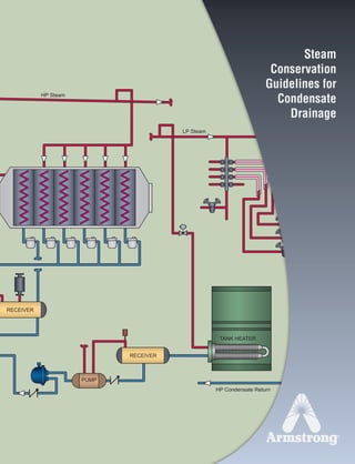
  • 1. HP Steam HP Condensate Return LP Steam TANK HEATER H K RECEIVER PUMP RECEIVER Steam Conservation Guidelines for Condensate Drainage
  • 2. Armstrong Steam and Condensate Group, 816 Maple St., Three Rivers, MI 49093 – USA Phone: (269) 273-1415 Fax: (269) 278-6555 armstronginternational.com Table of Contents 3 Recommendation Charts and Instructions for Use ......................................................................................................................CG-2 Steam Tables .................................................................................................................................................................................CG-3 Steam...Basic Concepts................................................................................................................................................................CG-5 The Inverted Bucket Steam Trap..................................................................................................................................................CG-9 The Float & Thermostatic Steam Trap........................................................................................................................................CG-11 The Controlled Disc Steam Trap.................................................................................................................................................CG-12 The Thermostatic Steam Trap ....................................................................................................................................................CG-13 The Automatic Differential Condensate Controller.....................................................................................................................CG-14 Steam Trap Selection..................................................................................................................................................................CG-15 How to Trap: Steam Distribution Systems........................................................................................................................................................CG-17 Steam Tracer Lines .....................................................................................................................................................................CG-21 Superheated Steam Lines...........................................................................................................................................................CG-23 Space Heating Equipment ..........................................................................................................................................................CG-25 Process Air Heaters.....................................................................................................................................................................CG-28 Shell and Tube Heat Exchangers...............................................................................................................................................CG-29 Evaporators..................................................................................................................................................................................CG-32 Jacketed Kettles ..........................................................................................................................................................................CG-35 Closed Stationary Steam Chamber Equipment .........................................................................................................................CG-37 Rotating Dryers Requiring Syphon Drainage.............................................................................................................................CG-39 Flash Tanks..................................................................................................................................................................................CG-41 Steam Absorption Machines .......................................................................................................................................................CG-43 Trap Selection and Safety Factors .............................................................................................................................................CG-44 Installation and Testing................................................................................................................................................................CG-45 Troubleshooting ...........................................................................................................................................................................CG-49 Pipe Sizing Steam Supply and Condensate Return Lines ........................................................................................................CG-50 Useful Engineering Tables...........................................................................................................................................................CG-53 Conversion Factors .....................................................................................................................................................................CG-54 Specific Heat - Specific Gravity...................................................................................................................................................CG-55 © 2011 Armstrong International, Inc. 13800 N101-Revised 2-11_838_Cons_Guide.qxd 2/8/11 10:13 AM Page 5
  • 3. Bringing Energy Down to Earth Say energy. Think environment. And vice versa. Any company that is energy conscious is also environmentally conscious. Less energy consumed means less waste, fewer emissions and a healthier environment. In short, bringing energy and environment together lowers the cost industry must pay for both. By helping companies manage energy, Armstrong products and services are also helping to protect the environment. Armstrong has been sharing know-how since we invented the energy-efficient inverted bucket steam trap in 1911. In the years since, customers’ savings have proven again and again that knowledge not shared is energy wasted. Armstrong’s developments and improvements in steam trap design and function have led to countless savings in energy, time and money. This section has grown out of our decades of sharing and expanding what we’ve learned. It deals with the operating principles of steam traps and outlines their specific applications to a wide variety of products and industries. You’ll find it a useful complement to other Armstrong literature and the Armstrong Steam-A-ware™ software program for sizing and selecting steam traps, pressure reducing valves and water heaters, which can be requested through Armstrong’s Web site, armstronginternational.com. This section also includes Recommendation Charts that summarize our findings on which type of trap will give optimum performance in a given situation and why. Armstrong Steam and Condensate Group, 816 Maple St., Three Rivers, MI 49093 – USA Phone: (269) 273-1415 Fax: (269) 278-6555 armstronginternational.com IMPORTANT: This section is intended to summarize general principles of installation and operation of steam traps, as outlined above. Actual installation and operation of steam trapping equipment should be performed only by experienced personnel. Selection or installation should always be accompanied by competent technical assistance or advice. This data should never be used as a substitute for such technical advice or assistance. We encourage you to contact Armstrong or its local representative for further details. CG-1 13808 N101-Revised 2-11_838_Cons_Guide.qxd 2/3/11 12:24 PM Page CG1
  • 4. Armstrong Steam and Condensate Group, 816 Maple St., Three Rivers, MI 49093 – USA Phone: (269) 273-1415 Fax: (269) 278-6555 armstronginternational.com Instructions for Using the Recommendation Charts A quick reference Recommendation Chart appears throughout the “HOW TO TRAP” sections of this catalog, pages CG-17 to CG-43. A feature code system (ranging from A to Q) supplies you with “at-a-glance” information. The chart covers the type of steam traps and the major advantages that Armstrong feels are superior for each particular application. For example, assume you are looking for information concerning the proper trap to use on a gravity drained jacketed kettle. You would: 1. Turn to the “How to Trap Jacketed Kettles” section, pages CG-35 to CG-36, and look in the lower right-hand corner of page CG-35. The Recommendation Chart located there is reprinted below for your convenience. (Each section has a Recommendation Chart.) 2. Find “Jacketed Kettles, Gravity Drain” in the first column under “Equipment Being Trapped” and read to the right for Armstrong’s “1st Choice and Feature Code.” In this case, the first choice is an IBLV and the feature code letters B, C, E, K, N are listed. 3. Now refer to Chart CG-2 below, titled “How Various Types of Steam Traps Meet Specific Operating Requirements” and read down the extreme left-hand column to each of the letters B, C, E, K, N. The letter “B,” for example, refers to the trap’s ability to provide energy-conserving operation. 4. Follow the line for “B” to the right until you reach the column that corresponds to our first choice, in this case the inverted bucket. Based on tests and actual operating conditions, the energy-conserving performance of the inverted bucket steam trap has been rated “Excellent.” Follow this same procedure for the remaining letters. Abbreviations IB Inverted Bucket Trap IBLV Inverted Bucket Large Vent BM Bimetallic Trap F&T Float and Thermostatic Trap CD Controlled Disc Trap DC Automatic Differential Condensate Controller CV Check Valve T Thermic Bucket PRV Pressure Reducing Valve (1) Drainage of condensate is continuous. Discharge is intermittent. (6) Cast iron traps not recommended. (2) Can be continuous on low load. (7) In welded stainless steel construction – medium. (3) Excellent when “secondary steam” is utilized. (8) Can fail closed due to dirt. (4) Bimetallic and wafer traps – good. (9) Can fail either open or closed, depending upon the design (5) Not recommended for low pressure operations. of the bellows. CG2 Equipment Being Trapped 1st Choice and Feature Code Alternate Choice Jacketed Kettles Gravity Drain IBLV B, C, E, K, N F&T or Thermostatic Jacketed Kettles Syphon Drain DC B, C, E, G, H, K, N, P IBLV Chart CG-1. Recommendation Chart (See chart below for “Feature Code” References.) Feature Code Characteristic IB BM F&T Disc Thermostatic DC A Method of Operation (1) Intermittent (2) Intermittent Continuous Intermittent (2) Intermittent Continuous B Energy Conservation (Time in Service) Excellent Excellent Good Poor Fair (3) Excellent C Resistance to Wear Excellent Excellent Good Poor Fair Excellent D Corrosion Resistance Excellent Excellent Good Excellent Good Excellent E Resistance to Hydraulic Shock Excellent Excellent Poor Excellent (4) Poor Excellent F Vents Air and CO2 at Steam Temperature Yes No No No No Yes G Ability to Vent Air at Very Low Pressure (1/4 psig) Poor (5) NR Excellent (5) NR Good Excellent H Ability to Handle Start-Up Air Loads Fair Excellent Excellent Poor Excellent Excellent I Operation Against Back Pressure Excellent Excellent Excellent Poor Excellent Excellent J Resistance to Damage From Freezing (6) Good Good Poor Good Good Good K Ability to Purge System Excellent Good Fair Excellent Good Excellent L Performance on Very Light Loads Excellent Excellent Excellent Poor Excellent Excellent M Responsiveness to Slugs of Condensate Immediate Delayed Immediate Delayed Delayed Immediate N Ability to Handle Dirt Excellent Fair Poor Poor Fair Excellent O Comparative Physical Size (7) Large Small Large Small Small Large P Ability to Handle “Flash Steam” Fair Poor Poor Poor Poor Excellent Q Mechanical Failure (Open or Closed) Open Open Closed (8) Open (9) Open Chart CG-2. How Various Types of Steam Traps Meet Specific Operating Requirements 13808 N101-Revised 2-11_838_Cons_Guide.qxd 2/3/11 12:24 PM Page CG2
  • 5. Armstrong Steam and Condensate Group, 816 Maple St., Three Rivers, MI 49093 – USA Phone: (269) 273-1415 Fax: (269) 278-6555 armstronginternational.com What They Are…How to Use Them The heat quantities and temperature/ pressure relationships referred to in this section are taken from the Properties of Saturated Steam table. Definitions of Terms Used Saturated Steam is pure steam at the temperature that corresponds to the boiling temperature of water at the existing pressure. Absolute and Gauge Pressures Absolute pressure is pressure in pounds per square inch (psia) above a perfect vacuum. Gauge pressure is pressure in pounds per square inch above atmospheric pressure, which is 14.7 pounds per square inch absolute. Gauge pressure (psig) plus 14.7 equals absolute pressure. Or, absolute pressure minus 14.7 equals gauge pressure. Pressure/Temperature Relationship (Columns 1, 2 and 3). For every pressure of pure steam there is a corresponding temperature. Example: The temperature of 250 psig pure steam is always 406°F. Heat of Saturated Liquid (Column 4). This is the amount of heat required to raise the temperature of a pound of water from 32°F to the boiling point at the pressure and temperature shown. It is expressed in British ther- mal units (Btu). Latent Heat or Heat of Vaporization (Column 5). The amount of heat (expressed in Btu) required to change a pound of boiling water to a pound of steam. This same amount of heat is released when a pound of steam is condensed back into a pound of water. This heat quantity is different for every pressure/temperature combination, as shown in the steam table. Total Heat of Steam (Column 6). The sum of the Heat of the Liquid (Column 4) and Latent Heat (Column 5) in Btu. It is the total heat in steam above 32°F. Specific Volume of Liquid (Column 7). The volume per unit of mass in cubic feet per pound. Specific Volume of Steam (Column 8). The volume per unit of mass in cubic feet per pound. How the Table Is Used In addition to determining pressure/ temperature relationships, you can compute the amount of steam that will be condensed by any heating unit of known Btu output. Conversely, the table can be used to determine Btu output if steam condensing rate is known. In the application portion of this section, there are several references to the use of the steam table. Steam Tables Table CG-1. Properties of Saturated Steam (Abstracted from Keenan and Keyes, THERMODYNAMIC PROPERTIES OF STEAM, by permission of John Wiley & Sons, Inc.) Col. 1 Gauge Pressure Col. 2 Absolute Pressure (psia) Col. 3 Steam Temp. (°F) Col. 4 Heat of Sat. Liquid (Btu/lb) Col. 5 Latent Heat (Btu/lb) Col. 6 Total Heat of Steam (Btu/lb) Col. 7 Specific Volume of Sat. Liquid (cu ft/lb) Col. 8 Specific Volume of Sat. Steam (cu ft/lb) 29.743 0.08854 32.00 0.00 1075.8 1075.8 0.016022 3306.00 29.515 0.2 53.14 21.21 1063.8 1085.0 0.016027 1526.00 27.886 1.0 101.74 69.70 1036.3 1106.0 0.016136 333.60 19.742 5.0 162.24 130.13 1001.0 1131.0 0.016407 73.52 9.562 10.0 193.21 161.17 982.1 1143.3 0.016590 38.42 7.536 11.0 197.75 165.73 979.3 1145.0 0.016620 35.14 5.490 12.0 201.96 169.96 976.6 1146.6 0.016647 32.40 3.454 13.0 205.88 173.91 974.2 1148.1 0.016674 30.06 1.418 14.0 209.56 177.61 971.9 1149.5 0.016699 28.04 0.0 14.696 212.00 180.07 970.3 1150.4 0.016715 26.80 1.3 16.0 216.32 184.42 967.6 1152.0 0.016746 24.75 2.3 17.0 219.44 187.56 965.5 1153.1 0.016768 23.39 5.3 20.0 227.96 196.16 960.1 1156.3 0.016830 20.09 10.3 25.0 240.07 208.42 952.1 1160.6 0.016922 16.30 15.3 30.0 250.33 218.82 945.3 1164.1 0.017004 13.75 20.3 35.0 259.28 227.91 939.2 1167.1 0.017078 11.90 25.3 40.0 267.25 236.03 933.7 1169.7 0.017146 10.50 30.3 45.0 274.44 243.36 928.6 1172.0 0.017209 9.40 40.3 55.0 287.07 256.30 919.6 1175.9 0.017325 7.79 50.3 65.0 297.97 267.50 911.6 1179.1 0.017429 6.66 60.3 75.0 307.60 277.43 904.5 1181.9 0.017524 5.82 70.3 85.0 316.25 286.39 897.8 1184.2 0.017613 5.17 80.3 95.0 324.12 294.56 891.7 1186.2 0.017696 4.65 90.3 105.0 331.36 302.10 886.0 1188.1 0.017775 4.23 100.0 114.7 337.90 308.80 880.0 1188.8 0.017850 3.88 110.3 125.0 344.33 315.68 875.4 1191.1 0.017922 3.59 120.3 135.0 350.21 321.85 870.6 1192.4 0.017991 3.33 125.3 140.0 353.02 324.82 868.2 1193.0 0.018024 3.22 130.3 145.0 355.76 327.70 865.8 1193.5 0.018057 3.11 140.3 155.0 360.50 333.24 861.3 1194.6 0.018121 2.92 150.3 165.0 365.99 338.53 857.1 1195.6 0.018183 2.75 160.3 175.0 370.75 343.57 852.8 1196.5 0.018244 2.60 180.3 195.0 379.67 353.10 844.9 1198.0 0.018360 2.34 200.3 215.0 387.89 361.91 837.4 1199.3 0.018470 2.13 225.3 240.0 397.37 372.12 828.5 1200.6 0.018602 1.92 250.3 265.0 406.11 381.60 820.1 1201.7 0.018728 1.74 300.0 417.33 393.84 809.0 1202.8 0.018896 1.54 400.0 444.59 424.00 780.5 1204.5 0.019340 1.16 450.0 456.28 437.20 767.4 1204.6 0.019547 1.03 500.0 467.01 449.40 755.0 1204.4 0.019748 0.93 600.0 486.21 471.60 731.6 1203.2 0.02013 0.77 900.0 531.98 526.60 668.8 1195.4 0.02123 0.50 1200.0 567.22 571.70 611.7 1183.4 0.02232 0.36 1500.0 596.23 611.60 556.3 1167.9 0.02346 0.28 1700.0 613.15 636.30 519.6 1155.9 0.02428 0.24 2000.0 635.82 671.70 463.4 1135.1 0.02565 0.19 2500.0 668.13 730.60 360.5 1091.1 0.02860 0.13 2700.0 679.55 756.20 312.1 1068.3 0.03027 0.11 3206.2 705.40 902.70 0.0 902.7 0.05053 0.05 InchesofVacuumPSIG CG3 8 13808 N101-Revised 2-11_838_Cons_Guide.qxd 2/3/11 12:24 PM Page CG3
  • 6. 400 300 200 100 0 100 200 300 400 PRESSURE AT WHICH CONDENSATE IS FORMED—LBS/SQ IN CUFTFLASHSTEAM PERCUFTOFCONDENSATE 30 0 5 10 15 20 25 –20 300250200150100500 PERCENTAGEOFFLASHSTEAM PSI FROM WHICH CONDENSATE IS DISCHARGED CURVE BACK PRESS. LBS/SQ IN A B C D E F G 10 5 0 10 20 30 40 – – B C D E F A G Armstrong Steam and Condensate Group, 816 Maple St., Three Rivers, MI 49093 – USA Phone: (269) 273-1415 Fax: (269) 278-6555 armstronginternational.com Steam Tables Flash Steam (Secondary) What is flash steam? When hot condensate or boiler water, under pressure, is released to a lower pressure, part of it is re-evaporated, becoming what is known as flash steam. Why is it important? This flash steam is important because it contains heat units that can be used for economical plant operation—and which are otherwise wasted. How is it formed? When water is heated at atmospheric pressure, its temperature rises until it reaches 212°F, the highest temperature at which water can exist at this pressure. Additional heat does not raise the temperature, but converts the water to steam. The heat absorbed by the water in raising its temperature to boiling point is called “sensible heat” or heat of saturated liquid. The heat required to convert water at boiling point to steam at the same temperature is called “latent heat.” The unit of heat in common use is the Btu, which is the amount of heat required to raise the temperature of one pound of water 1°F at atmospheric pressure. If water is heated under pressure, however, the boiling point is higher than 212°F, so the sensible heat required is greater. The higher the pressure, the higher the boiling temperature and the higher the heat content. If pressure is reduced, a certain amount of sensible heat is released. This excess heat will be absorbed in the form of latent heat, causing part of the water to “flash” into steam. Condensate at steam temperature and under 100 psig pressure has a heat content of 308.8 Btu per pound. (See Column 4 in Steam Table.) If this condensate is discharged to atmospheric pressure (0 psig), its heat content instantly drops to 180 Btu per pound. The surplus of 128.8 Btu re-evaporates or flashes a portion of the condensate. The percentage that will flash to steam can be computed using the formula: % flash steam = x 100 SH = Sensible heat in the condensate at the higher pressure before discharge. SL = Sensible heat in the condensate at the lower pressure to which discharge takes place. H = Latent heat in the steam at the lower pressure to which the condensate has been discharged. % flash steam = x 100 =13.3% Chart CG-3 shows the amount of secondary steam that will be formed when discharging condensate to different pressures. Other useful tables will be found on page CG-53 (Useful Engineering Tables). SH - SL H 308.8 - 180 970.3 Chart CG-3. Percentage of flash steam formed when discharging condensate to reduced pressure. Chart CG-4. Volume of flash steam formed when one cubic foot of condensate is discharged to atmospheric pressure. CG4 9 13808 N101-Revised 2-11_838_Cons_Guide.qxd 2/3/11 12:24 PM Page CG4
  • 7. + 880 Btu= 1 lb water at 70°F, 0 psig 1 lb water at 338°F, 100 psig+ 270 Btu= 1 lb steam at 338°F, 100 psig Condensate Steam 1 lb water at 70°F 1 lb water at 212°F 1 lb steam at 212°F + 970 Btu= + 142 Btu= Steam…Basic Concepts Steam is an invisible gas generated by adding heat energy to water in a boiler. Enough energy must be added to raise the temperature of the water to the boiling point. Then additional energy—without any further increase in temperature—changes the water to steam. Steam is a very efficient and easily controlled heat transfer medium. It is most often used for transporting energy from a central location (the boiler) to any number of locations in the plant where it is used to heat air, water or process applications. As noted, additional Btu are required to make boiling water change to steam. These Btu are not lost but stored in the steam ready to be released to heat air, cook tomatoes, press pants or dry a roll of paper. The heat required to change boiling water into steam is called the heat of vaporization or latent heat. The quantity is different for every pressure/temperature combination, as shown in the steam tables. Steam at Work… How the Heat of Steam Is Utilized Heat flows from a higher temperature level to a lower temperature level in a process known as heat transfer. Starting in the combustion chamber of the boiler, heat flows through the boiler tubes to the water. When the higher pressure in the boiler pushes steam out, it heats the pipes of the distribution system. Heat flows from the steam through the walls of the pipes into the cooler surrounding air. This heat transfer changes some of the steam back into water. That’s why distribution lines are usually insulated to minimize this wasteful and undesirable heat transfer. When steam reaches the heat exchangers in the system, the story is different. Here the transfer of heat from the steam is desirable. Heat flows to the air in an air heater, to the water in a water heater or to food in a cooking kettle. Nothing should interfere with this heat transfer. Condensate Drainage… Why It’s Necessary Condensate is the by-product of heat transfer in a steam system. It forms in the distribution system due to unavoidable radiation. It also forms in heating and process equipment as a result of desirable heat transfer from the steam to the substance heated. Once the steam has condensed and given up its valuable latent heat, the hot condensate must be removed immediately. Although the available heat in a pound of condensate is negligible as compared to a pound of steam, condensate is still valuable hot water and should be returned to the boiler. Definitions n The Btu. A Btu—British thermal unit—is the amount of heat energy required to raise the temperature of one pound of cold water by 1°F. Or, a Btu is the amount of heat energy given off by one pound of water in cooling, say, from 70°F to 69°F. n Temperature. The degree of hotness with no implication of the amount of heat energy available. n Heat. A measure of energy available with no implication of temperature. To illustrate, the one Btu that raises one pound of water from 39°F to 40°F could come from the surrounding air at a temperature of 70°F or from a flame at a temperature of 1,000°F. Armstrong Steam and Condensate Group, 816 Maple St., Three Rivers, MI 49093 – USA Phone: (269) 273-1415 Fax: (269) 278-6555 armstronginternational.com Figure CG-1. These drawings show how much heat is required to generate one pound of steam at atmospheric pressure. Note that it takes 1 Btu for every 1° increase in temperature up to the boiling point, but that it takes more Btu to change water at 212°F to steam at 212°F. Figure CG-2. These drawings show how much heat is required to generate one pound of steam at 100 pounds per square inch pressure. Note the extra heat and higher temperature required to make water boil at 100 pounds pressure than at atmospheric pressure. Note, too, the lesser amount of heat required to change water to steam at the higher temperature. CG5 13808 N101-Revised 2-11_838_Cons_Guide.qxd 2/3/11 12:24 PM Page CG5
  • 8. 100 psig 337.9°F 50.3 psig 297.97°F Trap Trap Trap Trap Trap Vent PRV Trap A B Armstrong Steam and Condensate Group, 816 Maple St., Three Rivers, MI 49093 – USA Phone: (269) 273-1415 Fax: (269) 278-6555 armstronginternational.com Steam…Basic Concepts The need to drain the distribution system. Condensate lying in the bottom of steam lines can be the cause of one kind of water hammer. Steam traveling at up to 100 miles per hour makes “waves” as it passes over this condensate Fig. CG-4). If enough condensate forms, high-speed steam pushes it along, creating a dangerous slug that grows larger and larger as it picks up liquid in front of it. Anything that changes the direction—pipe fittings, regulating valves, tees, elbows, blind flanges—can be destroyed. In addition to damage from this “battering ram,” high-velocity water may erode fittings by chipping away at metal surfaces. The need to drain the heat transfer unit. When steam comes in contact with condensate cooled below the temper- ature of steam, it can produce another kind of water hammer known as thermal shock. Steam occupies a much greater volume than condensate, and when it collapses suddenly, it can send shock waves throughout the system. This form of water hammer can damage equipment, and it signals that condensate is not being drained from the system. Obviously, condensate in the heat transfer unit takes up space and reduces the physical size and capacity of the equipment. Removing it quickly keeps the unit full of steam (Fig. CG-5). As steam condenses, it forms a film of water on the inside of the heat exchanger. Non-condensable gases do not change into liquid and flow away by gravity. Instead, they accumulate as a thin film on the surface of the heat exchanger—along with dirt and scale. All are potential barriers to heat transfer (Fig. CG-3). The need to remove air and CO2. Air is always present during equipment start-up and in the boiler feedwater. Feedwater may also contain dissolved carbonates, which release carbon dioxide gas. The steam velocity pushes the gases to the walls of the heat exchangers, where they may block heat transfer. This compounds the condensate drainage problem, because these gases must be removed along with the condensate. Figure CG-3. Potential barriers to heat transfer: steam heat and temperature must penetrate these potential barriers to do their work. Figure CG-6. Note that heat radiation from the distribution system causes condensate to form and, therefore, requires steam traps at natural low points or ahead of control valves. In the heat exchangers, traps perform the vital function of removing the condensate before it becomes a barrier to heat transfer. Hot condensate is returned through the traps to the boiler for reuse. Figure CG-5. Coil half full of condensate can’t work at full capacity. Figure CG-4. Condensate allowed to collect in pipes or tubes is blown into waves by steam passing over it until it blocks steam flow at point A. Condensate in area B causes a pressure differential that allows steam pressure to push the slug of condensate along like a battering ram. CG6 11 Condensate Steam Vapor 13808 N101-Revised 2-11_838_Cons_Guide.qxd 2/3/11 12:24 PM Page CG6
  • 9. 450 425 400 375 350 325 300 275 250 225 200 150 100 300 250 200 150 100 75 50 25 0 100 90 80 70 60 50 40 30 20 10 0 100 90 80 70 60 50 40 30 20 10 0 PERCENT AIR BY VOLUME–% PRESSURE–PSIG 300 250 200 150 100 75 50 25 0 0 450 425 400 375 350 325 300 275 250 225 200 150 100 0 TEMPERATUREF Steam…Basic Concepts Effect of Air on Steam Temperature When air and other gases enter the steam system, they consume part of the volume that steam would otherwise occupy. The temperature of the air/steam mixture falls below that of pure steam. Figure CG-7 explains the effect of air in steam lines. Table CG-2 and Chart CG-5 show the vari- ous temperature reductions caused by air at various per- centages and pressures. Effect of Air on Heat Transfer The normal flow of steam toward the heat exchanger sur- face carries air and other gases with it. Since they do not condense and drain by gravity, these non-condensable gases set up a barrier between the steam and the heat exchanger surface. The excellent insulating properties of air reduce heat transfer. In fact, under certain conditions as little as 1/2 of 1% by volume of air in steam can reduce heat transfer efficiency by 50% (Fig. CG-8). When non-condensable gases (primarily air) continue to accumulate and are not removed, they may gradually fill the heat exchanger with gases and stop the flow of steam altogether. The unit is then “air bound.” Corrosion Two primary causes of scale and corrosion are carbon dioxide (CO2) and oxygen. CO2 enters the system as carbonates dissolved in feedwater and, when mixed with cooled condensate, creates carbonic acid. Extremely corrosive, carbonic acid can eat through piping and heat exchangers (Fig. CG-9). Oxygen enters the system as gas dissolved in the cold feedwater. It aggravates the action of carbonic acid, speeding corrosion and pitting iron and steel surfaces (Fig. CG-10). Eliminating the Undesirables To summarize, traps must drain condensate because it can reduce heat transfer and cause water hammer. Traps should evacuate air and other non-condensable gases because they can reduce heat transfer by reducing steam temperature and insulating the system. They can also foster destructive corrosion. It’s essential to remove condensate, air and CO2 as quickly and completely as possible. A steam trap, which is simply an automatic valve that opens for condensate, air and CO2 and closes for steam, does this job. For economic reasons, the steam trap should do its work for long periods with minimum attention. Armstrong Steam and Condensate Group, 816 Maple St., Three Rivers, MI 49093 – USA Phone: (269) 273-1415 Fax: (269) 278-6555 armstronginternational.com Chart CG-5. Air Steam Mixture Temperature reduction caused by various percentages of air at differing pres- sures. This chart determines the percentage of air with known pressure and tem- perature by determining the point of intersection between pressure, temperature and percentage of air by volume. As an example, assume system pressure of 250 psig with a temperature at the heat exchanger of 375°F. From the chart, it is deter- mined that there is 30% air by volume in the steam. Figure CG-7. Chamber containing air and steam delivers only the heat of the partial pressure of the steam, not the total pressure. Steam chamber 100% steam Total pressure 100 psia Steam pressure 100 psia Steam temperature 327.8°F Steam chamber 90% steam and 10% air Total pressure 100 psia Steam pressure 90 psia Steam temperature 320.3°F Pressure (psig) Temp. of Steam, No Air Present (°F) 10% 20% 30% 10.3 240.1 234.3 228.0 220.9 25.3 267.3 261.0 254.1 246.4 50.3 298.0 291.0 283.5 275.1 75.3 320.3 312.9 304.8 295.9 100.3 338.1 330.3 321.8 312.4 Temp. of Steam Mixed With Various Percentages of Air (by Volume) (°F) Table CG-2. Temperature Reduction Caused by Air CG7 12 13808 N101-Revised 2-11_838_Cons_Guide.qxd 2/3/11 12:24 PM Page CG7
  • 10. Armstrong Steam and Condensate Group, 816 Maple St., Three Rivers, MI 49093 – USA Phone: (269) 273-1415 Fax: (269) 278-6555 armstronginternational.com Steam…Basic Concepts What the Steam Trap Must Do The job of the steam trap is to get condensate, air and CO2 out of the system as quickly as they accumulate. In addition, for overall efficiency and economy, the trap must also provide: 1. Minimal steam loss. Table CG-3 shows how costly unattended steam leaks can be. 2. Long life and dependable service. Rapid wear of parts quickly brings a trap to the point of undependability. An efficient trap saves money by minimizing trap testing, repair, cleaning, downtime and associated losses. 3. Corrosion resistance. Working trap parts should be corrosion-resistant in order to combat the damaging effects of acidic or oxygen-laden condensate. 4. Air venting. Air can be present in steam at any time and especially on start-up. Air must be vented for efficient heat transfer and to prevent system binding. 5. CO2 venting. Venting CO2 at steam temperature will prevent the formation of carbonic acid. Therefore, the steam trap must function at or near steam temperature since CO2 dissolves in condensate that has cooled below steam temperature. 6. Operation against back pressure. Pressurized return lines can occur both by design and unintentionally. A steam trap should be able to operate against the actual back pressure in its return system. 7. Freedom from dirt problems. Dirt is an ever-present concern since traps are located at low points in the steam system. Condensate picks up dirt and scale in the piping, and solids may carry over from the boiler. Even particles passing through strainer screens are erosive and, therefore, the steam trap must be able to operate in the presence of dirt. A trap delivering anything less than all these desirable operating/design features will reduce the efficiency of the system and increase costs. When a trap delivers all these features the system can achieve: 1. Fast heat-up of heat transfer equipment 2. Maximum equipment temperature for enhanced steam heat transfer 3. Maximum equipment capacity 4. Maximum fuel economy 5. Reduced labor per unit of output 6. Minimum maintenance and a long trouble-free service life Sometimes an application may demand a trap without these design features, but in the vast majority of applica- tions the trap which meets all the requirements will deliver the best results. Figure CG-9. CO2 gas combines with condensate allowed to cool below steam temperature to form carbonic acid, which corrodes pipes and heat transfer units. Note groove eaten away in the pipe illustrated. Figure CG-8. Steam condensing in a heat transfer unit moves air to the heat transfer surface, where it collects or “plates out” to form effective insulation. Figure CG-10. Oxygen in the system speeds corrosion (oxidation) of pipes, causing pitting such as shown here. Figs. CG-9 and CG-10 courtesy of Dearborn Chemical Company. Size of Orifice (in) Lbs Steam Wasted Per Month (USD) (USD) Total Cost Per Month Total Cost Per Year 1/2 553,000 $5,530.00 $66,360.00 7/16 423,500 4,235.00 50,820.00 3/8 311,000 3,110.00 37,320.00 5/16 216,000 2,160.00 25,920.00 1/4 138,000 1,380.00 16,560.00 3/16 78,000 780.00 9,360.00 1/8 34,500 345.50 4,140.00 The steam loss values assume typical condensate load for drip trap applications. Armstrong methodology for steam trap management and condensate return is sanctioned by the Clean Development Mechanism of the United Nations Framework Convention on Climate Change. Table CG-3. Cost of Various Sized Steam Leaks at 100 psi (69 bar) (Assuming steam costs $10.00/1,000 lbs) CG8 13 SteamCondensate 13800 N101-Revised 2-11_838_Cons_Guide.qxd 2/4/11 11:16 AM Page CG8
  • 11. Valve Closed Valve Wide Open Flow Here Picks Up Dirt The Inverted Bucket Steam Trap The Armstrong inverted submerged bucket steam trap is a mechanical trap that operates on the difference in density between steam and water. See Fig. CG-11. Steam entering the inverted submerged bucket causes the bucket to float and close the discharge valve. Condensate entering the trap changes the bucket to a weight that sinks and opens the trap valve to discharge the condensate. Unlike other mechanical traps, the inverted bucket also vents air and carbon dioxide continuously at steam temperature. This simple principle of condensate removal was introduced by Armstrong in 1911. Years of improvement in materials and manufacturing have made today’s Armstrong inverted bucket traps virtually unmatched in operating efficiency, dependability and long life. Long, Energy-Efficient Service Life At the heart of the Armstrong inverted bucket trap is a unique leverage system that multiplies the force provided by the bucket to open the valve against pressure. There are no fixed pivots to wear or create friction. It is designed to open the discharge orifice for maximum capacity. Since the buck- et is open at the bottom, it is resistant to damage from water hammer. Wearing points are heavily reinforced for long life. An Armstrong inverted bucket trap can continue to conserve energy even in the presence of wear. Gradual wear slightly increases the diameter of the seat and alters the shape and diameter of the ball valve. But as this occurs, the ball merely seats itself deeper—preserving a tight seal. Reliable Operation The Armstrong inverted bucket trap owes much of its reliability to a design that makes it virtually free of dirt problems. Note that the valve and seat are at the top of the trap. The larger particles of dirt fall to the bottom, where they are pulverized under the up-and-down action of the bucket. Since the valve of an inverted bucket is either closed or fully open, there is free passage of dirt particles. In addition, the swift flow of condensate from under the bucket’s edge creates a unique self-scrubbing action that sweeps dirt out of the trap. The inverted bucket has only two moving parts—the valve lever assembly and the bucket. That means no fixed points, no complicated linkages—nothing to stick, bind or clog. Corrosion-Resistant Parts The valve and seat of Armstrong inverted bucket traps are high chrome stainless steel, ground and lapped. All other working parts are wear- and corrosion-resistant stainless steel. Operation Against Back Pressure High pressure in the discharge line simply reduces the differential across the valve. As back pressure approaches that of inlet pressure, discharge becomes continuous just as it does on the very low pressure differentials. Back pressure has no adverse effect on inverted bucket trap operation other than capacity reduction caused by the low differential. There is simply less force required by the bucket to pull the valve open, cycling the trap. Armstrong Steam and Condensate Group, 816 Maple St., Three Rivers, MI 49093 – USA Phone: (269) 273-1415 Fax: (269) 278-6555 armstronginternational.com 1. Steam trap is installed in drain line between steam-heated unit and condensate return header. On start-up, bucket is down and valve is wide open. As initial flood of condensate enters the trap and flows under bottom of bucket, it fills trap body and completely submerges bucket. Condensate then discharges through wide-open valve to return header. 2. Steam also enters trap under bottom of bucket, where it rises and collects at top, imparting buoyancy. Bucket then rises and lifts valve toward its seat until valve is snapped tightly shut. Air and carbon dioxide continually pass through bucket vent and collect at top of trap. Any steam passing through vent is condensed by radiation from trap. Condensate Steam Air Flashing Condensate Figure CG-11. Operation of the Inverted Bucket Steam Trap (at pressures close to maximum) CG9 14 13808 N101-Revised 2-11_838_Cons_Guide.qxd 2/3/11 12:24 PM Page CG9
  • 12. Valve Wide Open Self Scrubbing Flow Valve Closed 3. As the entering condensate starts to fill the bucket, the bucket begins to exert a pull on the lever. As the condensate continues to rise, more force is exerted until there is enough to open the valve against the differential pressure. 4. As the valve starts to open, the pressure force across the valve is reduced. The bucket then sinks rapidly and fully opens the valve. Accumulated air is discharged first, followed by condensate. The flow under the bottom of the bucket picks up dirt and sweeps it out of the trap. Discharge continues until more steam floats the bucket, and the cycle repeats. Armstrong Steam and Condensate Group, 816 Maple St., Three Rivers, MI 49093 – USA Phone: (269) 273-1415 Fax: (269) 278-6555 armstronginternational.com The Inverted Bucket Steam Trap Types of Armstrong Inverted Bucket Traps Available to Meet Specific Requirements The availability of inverted bucket traps in different body materials, piping configurations and other variables permits flexibility in applying the right trap to meet specific needs. See Table CG-4. 1. All-Stainless Steel Traps. Sealed, tamper-proof stain- less steel bodies enable these traps to withstand freeze- ups without damage. They may be installed on tracer lines, outdoor drips and other services subject to freez- ing. For pressures to 650 psig and temperatures to 800°F. 2. Cast Iron Traps. Standard inverted bucket traps for general service at pressures to 250 psig and temperatures to 450°F. Offered with side connections, side connections with integral strainers and bottom inlet—top outlet connections. 3. Forged Steel Traps. Standard inverted bucket traps for high pressure, high temperature services (including superheated steam) to 2,700 psig at 1,050°F. 4. Cast Stainless Steel Traps. Standard inverted bucket traps for high capacity, corrosive service. Repairable. For pressures to 700 psig and temperatures to 506°F. CG10 Cast Iron Stainless Steel Forged Steel Cast Steel Cast Stainless Steel Connections 1/2" thru 2-1/2" 3/8" thru 1" 1/2" thru 2" 1/2" thru 1" 1/2" thru 2" Type Connections Screwed Screwed, Socketweld Screwed, Socketweld or Flanged Screwed, Socketweld or Flanged Screwed, Socketweld or Flanged Operating Pressure (psig) 0 thru 250 0 thru 650 0 thru 2,700 0 thru 600 0 thru 700 Capacity (lbs/hr) To 20,000 To 4,400 to 20,000 To 4,400 To 20,000 Table CG-4. Typical Design Parameters for Inverted Bucket Traps 15 Body and Cap Materials 13808 N101-Revised 2-11_838_Cons_Guide.qxd 2/3/11 12:24 PM Page CG10
  • 13. The Float and Thermostatic Steam Trap The float and thermostatic trap is a mechanical trap that operates on both density and temperature principles. The float valve operates on the density principle: A lever con- nects the ball float to the valve and seat. Once condensate reaches a certain level in the trap the float rises, opening the orifice and draining condensate. A water seal formed by the condensate prevents live steam loss. Since the discharge valve is under water, it is not capable of venting air and non-condensables. When the accumulation of air and non-condensable gases causes a significant tem- perature drop, a thermostatic air vent in the top of the trap discharges it. The thermostatic vent opens at a temperature a few degrees below saturation so it’s able to handle a large volume of air—through an entirely separate orifice—but at a slightly reduced temperature. Armstrong F&T traps provide high air-venting capacity, respond immediately to condensate and are suitable for both industrial and HVAC applications. Reliable Operation on Modulating Steam Pressure Modulating steam pressure means that the pressure in the heat exchange unit being drained can vary anywhere from the maximum steam supply pressure down to vacuum under certain conditions. Thus, under conditions of zero pressure, only the force of gravity is available to push condensate through a steam trap. Substantial amounts of air may also be liberated under these conditions of low steam pressure. The efficient operation of the F&T trap meets all of these specialized requirements. High Back Pressure Operation Back pressure has no adverse effect on float and thermostatic trap operation other than capacity reduction due to low differential. The trap will not fail to close and will not blow steam due to the high back pressure. Armstrong Steam and Condensate Group, 816 Maple St., Three Rivers, MI 49093 – USA Phone: (269) 273-1415 Fax: (269) 278-6555 armstronginternational.com Figure CG-12. Operation of the F&T Steam Trap 1. On start-up, low system pressure forces air out through the thermostatic air vent. A high condensate load normally follows air venting and lifts the float, which opens the main valve. The remaining air continues to discharge through the open vent. 2. When steam reaches the trap, the thermostatic air vent closes in response to higher temperature. Condensate continues to flow through the main valve, which is positioned by the float to discharge condensate at the same rate that it flows to the trap. 3. As air accumulates in the trap, the temperature drops below that of saturated steam. The balanced pressure thermostatic air vent opens and discharges air. NOTE: These operational schematics of the F&T trap do not represent actual trap configuration. Condensate Steam Air Cast Iron Cast Steel Connections 1/2" thru 3" 1/2" thru 3" Type Connections Screwed or Flanged Screwed, Socketweld or Flanged Operating Pressure (psig) 0 thru 250 0 thru 465 Capacity (lbs/hr) To 208,000 To 280,000 Table CG-5. Typical Design Parameters for Float and Thermostatic Traps CG11 16 Body and Cap Materials 13808 N101-Revised 2-11_838_Cons_Guide.qxd 2/3/11 12:24 PM Page CG11
  • 14. Bimetallic steam traps have the ability to handle large start-up loads. As the trap increases in temperature, its stacked nickel-chrome bimetallic elements start to expand, allowing for tight shutoff as steam reaches the trap, thus preventing steam loss. In addition to its light weight and compact size, it offers resistance to water hammer. Titanium valve and seat on high-pressure bimetallic traps ensure extremely long service life in the harsh environment of superheated steam systems. Heating Chamber Control Chamber Control Disc Inlet Passage Outlet Passages High Velocity Flow Seat Control Chamber Disc is held against two concentric faces of seat Armstrong Steam and Condensate Group, 816 Maple St., Three Rivers, MI 49093 – USA Phone: (269) 273-1415 Fax: (269) 278-6555 armstronginternational.com The Controlled Disc Steam Trap CG12 The controlled disc steam trap is a time-delayed device that operates on the velocity principle. It contains only one moving part, the disc itself. Because it is very lightweight and compact, the CD trap meets the needs of many applications where space is limited. In addition to the disc trap’s simplicity and small size, it also offers advantages such as resistance to hydraulic shock, the complete discharge of all condensate when open and intermittent operation for a steady purging action. Operation of controlled disc traps depends on the changes in pressures in the chamber where the disc operates. The Armstrong CD trap will be open as long as cold condensate is flowing. When steam or flash steam reaches the inlet orifice, velocity of flow increases, pulling the disc toward the seat. Increasing pressure in the control chamber snaps the disc closed. The subsequent pressure reduction, necessary for the trap to open, is controlled by the heating chamber in the cap and a finite machined bleed groove in the disc. Once the system is up to temperature, the bleed groove controls the trap cycle rate. Unique Heating Chamber The unique heating chamber in Armstrong’s controlled disc traps surrounds the disc body and control chamber. A controlled bleed from the chamber to the trap outlet controls the cycle rate. That means that the trap design—not ambient conditions—controls the cycle rate. Without this controlling feature, rain, snow and cold ambient conditions would upset the cycle rate of the trap. 1. On start-up, condensate and air entering the trap pass through the heating chamber, around the control chamber and through the inlet orifice. This flow lifts the disc off the inlet orifice, and the condensate flows through to the outlet passages. 2. Steam enters through the inlet passage and flows under the control disc. The flow velocity across the face of the control disc increases, creating a low pressure that pulls the disc toward the seat. 3. The disc closes against two concentric faces of the seat, closing off the inlet passage and also trapping steam and condensate above the disc. There is a controlled bleeding of steam from the control chamber; flashing condensate helps main- tain the pressure in the control chamber. When the pressure above the disc is reduced, the incoming pressure lifts the disc off the seat. If condensate is present, it will be discharged, and the cycle repeats. Figure CG-13. Design and Operation of Controlled Disc Traps Condensate Steam Air Condensate and Steam Mixture Steel Connections 3/8" thru 1" Type Connections Screwed, Socketweld or Flanged Operating Pressure (psig) 10 thru 600 Capacity (lbs/hr) To 2,850 Table CG-6. Typical Design Parameters for Controlled Disc Traps 1. On start-up, the trap is cold, so the elements are flat and the valve is wide open, which results in air and condensate being easily removed from the system by working pressure. 2. With increasing temperature of the condensate, the bimetallic elements will start to expand and flex. 3. When set temperature is reached, the force of the elements is high enough to close the valve completely against the system pressure working on the valve. The Bimetallic Steam Trap Body and Cap Materials Carbon Steel Stainless Steel Connection Sizes Type Connections Screwed, Socketweld, Flanged Screwed, NPT, BSPT, Socketweld, Buttweld, Flanged Operating psig 0 - 250 200 - 900 Cold Water Capacity lb/hr Table CG-7. Typical Design Parameters for Bimetallic Traps 1/2", 3/4", 1" up to 11,000 Figure CG-14. Design and Operation of Bimetallic Steam Traps Condensate Steam Air Flashing Steam 17 Body and Cap Materials 13808 N101-Revised 2-11_838_Cons_Guide.qxd 2/3/11 12:24 PM Page CG12
  • 15. Alcohol Vapor Bulkhead Wafer Alcohol Liquid Alcohol Chamber Armstrong Steam and Condensate Group, 816 Maple St., Three Rivers, MI 49093 – USA Phone: (269) 273-1415 Fax: (269) 278-6555 armstronginternational.com The Thermostatic Steam Trap Armstrong thermostatic steam traps are available with balanced pressure bellows or wafer-type elements and are constructed in a wide variety of materials, including stainless steel, carbon steel and bronze. These traps are used on applications with very light condensate loads. Thermostatic Operation Thermostatic steam traps operate on the difference in temperature between steam and cooled condensate and air. Steam increases the pressure inside the thermostatic element, causing the trap to close. As condensate and non-condensable gases back up in the cooling leg, the temperature begins to drop, and the thermostatic element contracts and opens the valve. The amount of condensate backed up ahead of the trap depends on the load conditions, steam pressure and size of the piping. It is important to note that an accumulation of non-condensable gases can occur behind the condensate backup. NOTE: Thermostatic traps can also be used for venting air from a steam system. When air collects, the temperature drops and the thermostatic air vent automatically discharges the air at slightly below steam temperature throughout the entire operating pressure range. Figure CG-15. Operation of the Thermostatic Steam Trap 1. On start-up, condensate and air are pushed ahead of the steam directly through the trap. The thermostatic bellows element is fully contracted, and the valve remains wide open until steam approaches the trap. 2. As the temperature inside the trap increases, it quickly heats the charged bellows element, increasing the vapor pressure inside. When pressure inside the element becomes balanced with system pressure in the trap body, the spring effect of the bellows causes the element to expand, closing the valve. When temperature in the trap drops a few degrees below saturated steam temperature, imbalanced pres- sure contracts the bellows, opening the valve. Figure CG-16. Operation of Thermostatic Wafer Balanced Pressure Thermostatic Wafer operation is very similar to balanced pressure bellows described in Fig. CG- 15. The wafer is partially filled with a liquid. As the temperature inside the trap increases, it heats the charged wafer, increasing the vapor pressure inside. When the pressure inside the wafer exceeds the surrounding steam pressure, the wafer membrane is forced down on the valve seat, and the trap is closed. A temperature drop caused by condensate or non-con- densable gases cools and reduces the pressure inside the wafer, allowing the wafer to uncover the seat. Steam Condensate Condensate and Air CG13 Body and Cap Materials Bronze Carbon Steel Stainless Steel Stainless Steel Bronze Connections 1/2", 3/4" 1/2", 3/4" 1/4" thru 1" 1/2", 3/4" 1/2", 3/4", 1" Type Connections Screwed, Socketweld Screwed, Socketweld Screwed, Socketweld NPT Straight, Angle NPT Straight, Angle Operating Pressure (psig) 0 - 300 0 - 50 0 - 400 0 - 600 0 - 65 Capacity (lbs/hr) To 3,450 To 1,600 To 70 To 85 To 960 Table CG-8. Design Parameters for Thermostatic Traps Balanced Pressure Bellows Balanced Pressure Wafer 18 13808 N101-Revised 2-11_838_Cons_Guide.qxd 2/3/11 12:24 PM Page CG13
  • 16. Condensate Return DC Condensate Return To Secondary Steam Header DC Secondary Steam Bucket Inlet Condensate Discharge Valve Manual Metering Valve Outlet Condensate Live and Flash Steam Condensate and Secondary Steam DottedLinesIndicateFieldPiping Armstrong Steam and Condensate Group, 816 Maple St., Three Rivers, MI 49093 – USA Phone: (269) 273-1415 Fax: (269) 278-6555 armstronginternational.com The Automatic Differential Condensate Controller Armstrong automatic differential condensate controllers (DC) are designed to function on applications where condensate must be lifted from a drain point or in gravity drainage applications where increased velocity will aid in drainage. Lifting condensate from the drain point—often referred to as syphon drainage—reduces the pressure of condensate, causing a portion of it to flash into steam. Since ordinary steam traps are unable to distinguish flash steam and live steam, they close and impede drainage. Increased velocity with gravity drainage will aid in drawing the condensate and air to the DC. An internal steam by-pass controlled by a manual metering valve causes this increased velocity. Therefore, the condensate controller automatically vents the by-pass or secondary steam. This is then collect- ed for use in other heat exchangers or discharged to the condensate return line. Capacity considerations for draining equipment vary greatly according to the application. However, a single condensate controller provides sufficient capacity for most applications. Condensate Controller Operation Condensate, air and steam (live and flash) enter through the controller inlet. At this point flash steam and air are automat- ically separated from the condensate. Then they divert into the integral by-pass at a controlled rate, forming secondary steam (See Fig. CG-18). The valve is adjustable so it matches the amount of flash present under full capacity operation or to meet the velocity requirements of the system. The condensate discharges through a separate orifice controlled by the inverted bucket. Because of the dual orifice design, there is a preset controlled pressure differential for the secondary steam system, while maximum pressure differential is available to discharge the condensate. Figure CG-17. For the most efficient use of steam energy, Armstrong recommends this piping arrangement when secondary steam is collected and reused in heat transfer equipment. Figure CG-18. Condensate Controller Operation Piping arrangement when flash steam and non-condensables are to be removed and discharged directly to the condensate return line. Cast Iron Connections 1/2" thru 2" Type Connections Screwed Operating Pressure (psig) 0 thru 250 Capacity (lbs/hr) To 20,000 Table CG-9. Typical Design Parameters for the Automatic Differential Condensate Controller CG14 Steel 1" thru 2" Screwed 0 thru 650 To 20,000 19 Body and Cap Materials 13808 N101-Revised 2-11_838_Cons_Guide.qxd 2/3/11 12:24 PM Page CG14
  • 17. 10"-12" 6" Wrong Right Trap Selection To obtain the full benefits from the traps described in the preceding section, it is essential to select traps of the correct size and pressure for a given job and to install and maintain them properly. One of the purposes of this section is to supply the information to make that possible. Actual installation and operation of steam trapping equipment should be performed only by experienced personnel. Selection or installation should always be accompanied by competent technical assistance or advice. This section should never be used as a substitute for such technical advice or assistance. We encourage you to contact Armstrong or its local representative for further details. Basic Considerations Unit trapping is the use of a separate steam trap on each steam-condensing unit including, whenever possible, each separate chest or coil of a single machine. The discussion under the Short Circuiting heading explains the “why” of unit trapping versus group trapping. Rely on experience. Select traps with the aid of experience– either yours, the know-how of your Armstrong Representative or what others have learned in trapping similar equipment. Do-it-yourself sizing. Do-it-yourself sizing is simple with the aid of Steam-A-ware™ , Armstrong’s sizing and selection software program, which can be downloaded at www.armstrong-intl.com. Even without this computer program, you can easily size steam traps when you know or can calculate: 1. Condensate loads in lbs/hr 2. The safety factor to use 3. Pressure differential 4. Maximum allowable pressure 1. Condensate load. Each “How To” portion of this section contains formulas and useful information on steam condensing rates and proper sizing procedures. 2. Safety factor or experience factor to use. Users have found that they must generally use a safety factor in sizing steam traps. For example, a coil condensing 500 lbs/hr might require a trap that could handle up to 1,500 for best overall performance. This 3:1 safety factor takes care of varying condensate rates, occasional drops in pressure differential and system design factors. Safety factors will vary from a low of 1.5:1 to a high of 10:1. The safety factors in this book are based on years of user experience. Configuration affects safety factor. More important than ordinary load and pressure changes is the design of the steam-heated unit itself. Refer to Figs. CG-21, CG-22 and CG-23 showing three condensing units each producing 500 pounds of condensate per hour, but with safety factors of 2:1, 3:1 and 8:1. Armstrong Steam and Condensate Group, 816 Maple St., Three Rivers, MI 49093 – USA Phone: (269) 273-1415 Fax: (269) 278-6555 armstronginternational.com Figure CG-19. Two steam-consuming units drained by a single trap, referred to as group trapping, may result in short circuiting. Figure CG-20. Short circuiting is impos- sible when each unit is drained by its own trap. Higher efficiency is assured. Short Circuiting If a single trap connects more than one drain point, condensate and air from one or more of the units may fail to reach the trap. Any difference in condensing rates will result in a difference in the steam pressure drop. A pressure drop difference too small to register on a pressure gauge is enough to let steam from the higher pressure unit block the flow of air or condensate from the lower pressure unit. The net result is reduced heating, output and fuel waste (see Figs. CG-19 and CG-20). Figure CG-21. Continuous coil, constant pressure gravity flow to trap. 500 lbs/hr of condensate from a single copper coil at 30 psig. Gravity drainage to trap. Volume of steam space very small. 2:1 safety factor. Figure CG-22. Multiple pipes, modulated pressure gravity flow to trap. 500 lbs/hr of condensate from unit heater at 80 psig. Multiple tubes create minor short- circuiting hazard. Use 3:1 safety factor at 40 psig. Figure CG-23. Large cylinder, syphon drained. 500 lbs/hr from a 4' diameter, 10' long cylinder dryer with 115 cu ft of space at 30 psig. The safety factor is 3:1 with a DC and 8:1 with an IB. Identical Condensing Rates, Identical Pressures With Differing Safety Factors Condensate Steam CG15 20 13808 N101-Revised 2-11_838_Cons_Guide.qxd 2/3/11 12:24 PM Page CG15
  • 18. External Check Valve Trap Steam Main Water Seal Lift in feet Pressure drop over water seal to lift cold condensate Trap 4psi 3psi 2psi 1psi 1' 2' 3' 4' 5' 6' 7' 8' 9' Trap Inlet Pressure or Maximum Allowable Pressure (MAP) Differential Pressure or Maximum Operating Pressure (MOP) Back Pressure or Vacuum A B Armstrong Steam and Condensate Group, 816 Maple St., Three Rivers, MI 49093 – USA Phone: (269) 273-1415 Fax: (269) 278-6555 armstronginternational.com Trap Selection Economical steam trap/orifice selection. While an ade- quate safety factor is needed for best performance, too large a factor causes problems. In addition to higher costs for the trap and its installation, a needlessly oversized trap wears out more quickly. And in the event of a trap failure, an oversized trap loses more steam, which can cause water hammer and high back pressure in the return system. 3. Pressure differential. Maximum differential is the difference between boiler or steam main pressure or the downstream pressure of a PRV and return line pressure. See Fig. CG-24. The trap must be able to open against this pressure differential. NOTE: Because of flashing condensate in the return lines, don’t assume a decrease in pressure differential due to static head when elevating. Operating differential. When the plant is operating at capaci- ty, the steam pressure at the trap inlet may be lower than steam main pressure. And the pressure in the condensate return header may go above atmospheric. If the operating differential is at least 80% of the maxi- mum differential, it is safe to use maximum differential in selecting traps. Modulated control of the steam supply causes wide changes in pressure differential. The pressure in the unit drained may fall to atmospheric or even lower (vacuum). This does not prevent condensate drainage if the installation practices in this handbook are followed. IMPORTANT: Be sure to read the discussion to the right, which deals with less common but important reductions in pressure differential. 4. Maximum allowable pressure. The trap must be able to withstand the maximum allowable pressure of the system or design pressure. It may not have to operate at this pressure, but it must be able to contain it. As an example, the maximum inlet pressure is 350 psig and the return line pressure is 150 psig. This results in a differential pressure of 200 psi; however, the trap must be able to withstand 350 psig maximum allowable pressure. See Fig. CG-24. Factors Affecting Pressure Differential Except for failures of pressure control valves, differential pressure usually varies on the low side of the normal or design value. Variations in either the inlet or discharge pressure can cause this. Inlet pressure can be reduced below its normal value by: 1. A modulating control valve or temperature regulator. 2. “Syphon drainage.” Every 2' of lift between the drainage point and the trap reduces the inlet pressure (and the differential) by one psi. See Fig. CG-25. Discharge pressure can be increased above its normal value by: 1. Pipe friction. 2. Other traps discharging into a return system of limited capacity. 3. Elevating condensate. Every 2' of lift increases the discharge pressure (and the differential) by one psi when the discharge is only condensate. However, with flash present, the extra back pressure could be reduced to zero. See Fig. CG-26, noting the external check valve. Figure CG-24. “A” minus “B” is Pressure Differential: If “B” is back pressure, subtract it from “A”. If “B” is vacuum, add it to “A”. Figure CG-25. Condensate from gravity drain point is lifted to trap by a syphon. Every 2' of lift reduces pressure differ- ential by 1 psi. Note seal at low point and the trap’s internal check valve to prevent backflow. Figure CG-26. When trap valve opens, steam pressure will elevate conden- sate. Every 2' of lift reduces pressure differential by 1 psi. Condensate Steam CG16 21 13808 N101-Revised 2-11_838_Cons_Guide.qxd 2/3/11 12:24 PM Page CG16
  • 19. Boiler #1 Header Level Boiler #2 Trap Trap Typical Takeoffs to System Armstrong Steam and Condensate Group, 816 Maple St., Three Rivers, MI 49093 – USA Phone: (269) 273-1415 Fax: (269) 278-6555 armstronginternational.com How to Trap Steam Distribution Systems Steam distribution systems link boilers and the equipment actually using steam, transporting it to any location in the plant where its heat energy is needed. The three primary components of steam distribution systems are boiler headers, steam mains and branch lines. Each fulfills certain requirements of the system and, together with steam separators and steam traps, contributes to efficient steam use. Drip legs. Common to all steam distribution systems is the need for drip legs at various intervals (Fig. CG-27). These are provided to: 1. Let condensate escape by gravity from the fast-moving steam. 2. Store the condensate until the pressure differential can discharge it through the steam trap. Boiler Headers A boiler header is a specialized type of steam main that can receive steam from one or more boilers. It is most often a horizontal line which is fed from the top and in turn feeds the steam mains. It is important to trap the boiler header properly to assure that any carryover (boiler water and solids) is removed before distribution into the system. Steam traps that serve the header must be capable of discharging large slugs of carryover as soon as they are present. Resistance to hydraulic shock is also a consideration in the selection of traps. Trap selection and safety factor for boiler headers (saturated steam only). A 1.5:1 safety factor is recommended for virtually all boiler header applications. The required trap capacity can be obtained by using the following formula: Required Trap Capacity = Safety Factor x Load Connected to Boiler(s) x Anticipated Carryover (typically 10%). EXAMPLE: What size steam trap will be required on a connected load of 50,000 lbs/hr with an anticipated carryover of 10%? Using the formula: Required Trap Capacity = 1.5 x 50,000 x 0.10 = 7,500 lbs/hr. The ability to respond immediately to slugs of condensate, excellent resistance to hydraulic shock, dirt-handling ability and efficient operation on very light loads are features that make the inverted bucket the most suitable steam trap for this application. Installation. If steam flow through the header is in one direction only, a single steam trap is sufficient at the down- stream end. With a midpoint feed to the header (Fig. CG-28), or a similar two-directional steam flow arrangement, each end of the boiler header should be trapped. Figure CG-28. Boiler Headers Drip leg same as the header diameter up to 4..'' Above 4'', 1/2 header size, but never less than 4.'' Figure CG-27. Drip Leg Sizing The properly sized drip leg will capture condensate. Too small a drip leg can actually cause a venturi “piccolo” effect where pressure drop pulls condensate out of the trap. See Table CG-13 on page CG-19. Equipment Being Trapped 1st Choice and Feature Code Alternate Choice Boiler Header IBLV *F&T *On superheated steam never use an F&T type trap. Always use an IB with internal check valve and burnished valve and seat. Chart CG-6. Recommendation Chart (See Page CG-2 for “Feature Code” References.) M, E, L, N, B, Q Equipment Being Trapped 1st Choice, Feature Code and Alternate Choice(s) 0 - 30 psig Above 30 psig B, M, N, L, F, E, C, D, Q *IB *IB Alternate Choice F&T **F&T B, C, D, E, F, L, M, N, Q, J *IB *IB Alternate Choice *Provide internal check valve when pressures fluctuate. **Use IBLV above F&T pressure/temperature limitations. Thermostatic or CD NOTE: On superheated steam, use an IB with internal check valve and burnished valve Steam Mains and Branch Lines Steam Mains and Branch Lines Non-freezing Conditions Freezing Conditions and seat. 22 CG-17 13808 N101-Revised 2-11_838_Cons_Guide.qxd 2/3/11 12:24 PM Page CG17
  • 20. Armstrong Steam and Condensate Group, 816 Maple St., Three Rivers, MI 49093 – USA Phone: (269) 273-1415 Fax: (269) 278-6555 armstronginternational.com Steam Mains One of the most common uses of steam traps is the trapping of steam mains. These lines need to be kept free of air and condensate in order to keep steam-using equipment operating properly. Inadequate trapping on steam mains often leads to water hammer and slugs of condensate that can damage control valves and other equipment. There are two methods used for the warm-up of steam mains—supervised and automatic. Supervised warm-up is widely used for initial heating of large-diameter and/or long mains. The suggested method is for drip valves to be opened wide for free blow to the atmosphere before steam is admitted to the main. These drip valves are not closed until all or most of the warm-up condensate has been discharged. Then the traps take over the job of removing condensate that may form under operating conditions. Warm-up of principal piping in a power plant will follow much the same procedure. Automatic warm-up is when the boiler is fired, allowing the mains and some or all equipment to come up to pressure and temperature without manual help or supervision. CAUTION: Regardless of warm-up method, allow suffi- cient time during the warm-up cycle to minimize thermal stress and prevent any damage to the system. Trap selection and safety factor for steam mains (saturated steam only). Select trap to discharge conden- sate produced by radiation losses at running load. Sizing for start-up loads results in oversized traps, which may wear prematurely. Size drip legs to collect condensate during low-pressure, warm-up conditions. (See Table CG-13 on page CG-19.) Condensate loads of insulated pipe can be found in Table CG-10. All figures in the table assume the insulation to be 75% effective. For pressures or pipe sizes not included in the table, use the following formula: C = Where: C = Condensate in lbs/hr-foot A = External area of pipe in square feet (Table CG-10, Col. 2) U = Btu/sq ft/degree temperature difference/hr from Chart CG-7 (page CG-19) T1 = Steam temperature in °F T2 = Air temperature in °F E = 1 minus efficiency of insulation (Example: 75% efficient insulation: 1 - .75 = .25 or E = .25) H = Latent heat of steam (See Steam Table on page CG-3) How to Trap Steam Distribution Systems A x U x (T1-T2)E H Table CG-11. The Warming-Up Load From 70°F, Schedule 40 Pipe 2 15 30 60 125 180 250 Pipe Size (in) wt of Pipe Per ft (lbs) 1 1.69 .030 .037 .043 .051 .063 .071 .079 1-1/4 2.27 .040 .050 .057 .068 .085 .095 .106 1-1/2 2.72 .048 .059 .069 .082 .101 .114 .127 2 3.65 .065 .080 .092 .110 .136 .153 .171 2-1/2 5.79 .104 .126 .146 .174 .215 .262 .271 3 7.57 .133 .165 .190 .227 .282 .316 .354 3-1/2 9.11 .162 .198 .229 .273 .339 .381 .426 4 10.79 .190 .234 .271 .323 .400 .451 .505 5 14.62 .258 .352 .406 .439 .544 .612 .684 6 18.97 .335 .413 .476 .569 .705 .795 .882 8 28.55 .504 .620 .720 .860 1.060 1.190 1.340 10 40.48 .714 .880 1.020 1.210 1.500 1.690 1.890 12 53.60 .945 1.170 1.350 1.610 2.000 2.240 2.510 14 63.00 1.110 1.370 1.580 1.890 2.340 2.640 2.940 16 83.00 1.460 1.810 2.080 2.490 3.080 3.470 3.880 18 105.00 1.850 2.280 2.630 3.150 3.900 4.400 4.900 20 123.00 2.170 2.680 3.080 3.690 4.570 5.150 5.750 24 171.00 3.020 3.720 4.290 5.130 6.350 7.150 8.000 Steam Pressure, psig Pounds of Water Per Lineal Foot Table CG-10. Condensation in Insulated Pipes Carrying Saturated Steam in Quiet Air at 70°F (Insulation assumed to be 75% efficient.) 15 30 60 125 180 250 450 600 900 Pipe Size (in) sq ft Per Lineal ft 1 .344 .05 .06 .07 .10 .12 .14 .186 .221 .289 1-1/4 .434 .06 .07 .09 .12 .14 .17 .231 .273 .359 1-1/2 .497 .07 .08 .10 .14 .16 .19 .261 .310 .406 2 .622 .08 .10 .13 .17 .20 .23 .320 .379 .498 2-1/2 .753 .10 .12 .15 .20 .24 .28 .384 .454 .596 3 .916 .12 .14 .18 .24 .28 .33 .460 .546 .714 3-1/2 1.047 .13 .16 .20 .27 .32 .38 .520 .617 .807 4 1.178 .15 .18 .22 .30 .36 .43 .578 .686 .897 5 1.456 .18 .22 .27 .37 .44 .51 .698 .826 1.078 6 1.735 .20 .25 .32 .44 .51 .59 .809 .959 1.253 8 2.260 .27 .32 .41 .55 .66 .76 1.051 1.244 1.628 10 2.810 .32 .39 .51 .68 .80 .94 1.301 1.542 2.019 12 3.340 .38 .46 .58 .80 .92 1.11 1.539 1.821 2.393 14 3.670 .42 .51 .65 .87 1.03 1.21 1.688 1.999 2.624 16 4.200 .47 .57 .74 .99 1.19 1.38 1.927 2.281 2.997 18 4.710 .53 .64 .85 1.11 1.31 1.53 2.151 2.550 3.351 20 5.250 .58 .71 .91 1.23 1.45 1.70 2.387 2.830 3.725 24 6.280 .68 .84 1.09 1.45 1.71 2.03 2.833 3.364 4.434 Pounds of Condensate Per Hour Per Lineal Foot Pressure, psig Table CG-12. Pipe Weights Per Foot in Pounds Pipe Size (in) Schedule 40 Schedule 80 Schedule 160 XX Strong 1 1.69 2.17 2.85 3.66 1-1/4 2.27 3.00 3.76 5.21 1-1/2 2.72 3.63 4.86 6.41 2 3.65 5.02 7.45 9.03 2-1/2 5.79 7.66 10.01 13.69 3 7.57 10.25 14.32 18.58 3-1/2 9.11 12.51 — 22.85 4 10.79 14.98 22.60 27.54 5 14.62 20.78 32.96 38.55 6 18.97 28.57 45.30 53.16 8 28.55 43.39 74.70 72.42 10 40.48 54.74 116.00 — 12 53.60 88.60 161.00 — 14 63.00 107.00 190.00 — 16 83.00 137.00 245.00 — 18 105.00 171.00 309.00 — 20 123.00 209.00 379.00 — 24 171.00 297.00 542.00 — CG18 23 13808 N101-Revised 2-11_838_Cons_Guide.qxd 2/3/11 12:24 PM Page CG18
  • 21. 11 10 9 8 7 6 5 4.5 4.0 3.5 3.3 3.0 2.8 2.6 2.5 2.4 2.3 2.2 2.15 PSIG 11 10 9 8 7 6 5 4.5 4.0 3.5 3.3 3.0 2.8 2.6 2.5 2.4 2.3 2.2 2.15 2.10 5.3 10.3 15.3 25.3 50.3 75.3 100.3 150.3 250.3 450.3 600.3 900.3 1500.3 2400.3 PRESSURE IN LBS PER SQUARE INCH BTUPERSQFTPERHOURPERFTEMPERATUREDIFFERENCE TEMPERATURE DIFFERENCE 150 160 180 200 240 300 400 500 700 900 1050 1" 2"2" 3" 5"5" 2" 5" 6" 10" FLAT SURFACES How to Trap Steam Distribution Systems For traps installed between the boiler and the end of the steam main, apply a 2:1 safety factor. Apply a 3:1 safety factor for traps installed at the end of the main or ahead of reducing and shutoff valves that are closed part of the time. The inverted bucket trap is recommended because it can handle dirt and slugs of condensate and resists hydraulic shock. In addition, should an inverted bucket fail, it usually does so in the open position. Installation. Both methods of warm-up use drip legs and traps at all low spots or natural drainage points such as: Ahead of risers End of mains Ahead of expansion joints or bends Ahead of valves or regulators Install drip legs and drain traps even where there are no natural drainage points (See Figs. CG-29, CG-30 and CG-31). These should normally be installed at intervals of about 300' and never longer than 500'. On a supervised warm-up, make drip leg length at least 1-1/2 times the diameter of the main, but never less than 10". Make drip legs on automatic warm-ups a minimum of 28" in length. For both methods, it is a good practice to use a drip leg the same diameter as the main up to 4" pipe size and at least 1/2 of the diameter of the main above that, but never less than 4". See Table CG-13. Armstrong Steam and Condensate Group, 816 Maple St., Three Rivers, MI 49093 – USA Phone: (269) 273-1415 Fax: (269) 278-6555 armstronginternational.com Figure CG-29. Trap draining strainer ahead of PRV. Figure CG-30. Trap draining drip leg on main. Figure CG-31. Trap draining drip leg at riser. Distance “H” in inches ÷ 28 = psi static head for forcing water through the trap. Steam Mains D M H Drip leg same as the header diameter up to 4''. Above 4'', 1/2 header size, but never less than 4''. Chart CG-8. Recommendation Chart (See Page CG-2 for “Feature Code” References.) Equipment Being Trapped 1st Choice and Feature Code Alternate Choice Steam Separator IBLV *DC *DC is 1st choice where steam quality is 90% or less. M D Supervised Warm-Up Automatic Warm-Up 1/2 1/2 10 28 3/4 3/4 10 28 1 1 10 28 2 2 10 28 3 3 10 28 4 4 10 28 6 4 10 28 8 4 12 28 10 6 15 28 12 6 18 28 14 8 21 28 16 8 24 28 18 10 27 28 20 10 30 30 24 12 36 36 Drip Leg Length Min. (in) Steam Main Size (in) Drip Leg Diameter (in) H Table CG-13. Recommended Steam Main and Branch Line Drip Leg Sizing Chart CG-7. Btu Heat Loss Curves CG19 H B, M, L, E, F, N, Q M 24 13808 N101-Revised 2-11_838_Cons_Guide.qxd 2/3/11 12:24 PM Page CG19
  • 22. Armstrong Steam and Condensate Group, 816 Maple St., Three Rivers, MI 49093 – USA Phone: (269) 273-1415 Fax: (269) 278-6555 armstronginternational.com How to Trap Steam Distribution Systems Branch Lines Branch lines are take-offs from the steam mains supplying specific pieces of steam-using equipment. The entire system must be designed and hooked up to prevent accumulation of condensate at any point. Trap selection and safety factor for branch lines. The formula for computing condensate load is the same as that used for steam mains. Branch lines also have a recom- mended safety factor of 3:1. Installation. Recommended piping from the main to the control is shown in Fig. CG-32 for runouts under 10' and Fig. CG-33 for runouts over 10'. See Fig. CG-34 for piping when control valve must be below the main. Install a full pipe-size strainer ahead of each control valve as well as ahead of the PRV, if used. Provide blowdown valves, preferably with IB traps. A few days after starting the system, examine the strainer screens to see if cleaning is necessary. Separators Steam separators are designed to remove any condensate that forms within steam distribution systems. They are most often used ahead of equipment where especially dry steam is essential. They are also common on secondary steam lines, which by their very nature have a large percentage of entrained condensate. Important factors in trap selection for separators are the ability to handle slugs of condensate, provide good resist- ance to hydraulic shock and operate on light loads. Trap selection and safety factors for separators. Apply a 3:1 safety factor in all cases, even though different types of traps are recommended, depending on condensate and pressure levels. Use the following formula to obtain the required trap capacity: Required trap capacity in lbs/hr = safety factor x steam flow rate in lbs/hr x anticipated percent of condensate (typically 10% to 20%). EXAMPLE: What size steam trap will be required on a flow rate of 10,000 lbs/hr? Using the formula: Required trap capacity = 3 x 10,000 x 0.10 = 3,000 lbs/hr. The inverted bucket trap with large vent is recommended for separators. When dirt and hydraulic shock are not significant problems, an F&T type trap is an acceptable alternative. An automatic differential condensate controller may be pre- ferred in many cases. It combines the best features of both of the above and is recommended for large condensate loads that exceed the separating capability of the separator. Installation Connect traps to the separator drain line 10" to 12" below the separator with the drain pipe running the full size of the drain connection down to the trap take-off (Fig. CG-35). The drain pipe and dirt pocket should be the same size as the drain connection. Figure CG-33. Piping for runout greater than 10'. Drip leg and trap required ahead of control valve. Strainer ahead of control valve can serve as drip leg if blowdown connection runs to an inverted bucket trap. This will also minimize the strainer cleaning problem. Trap should be equipped with an internal check valve or a swing check installed ahead of the trap. Figure CG-34. Regardless of the length of the runout, a drip leg and trap are required ahead of the control valve located below steam supply. If coil is above control valve, a trap should also be installed at downstream side of control valve. Figure CG-35. Drain downstream side of separator. Full-size drip leg and dirt pocket are required to ensure positive and fast flow of condensate to the trap. Figure CG-32. Piping for runout less than 10 ft. No trap required unless pitch back to supply header is less than 1/2'' per ft. 10' or Less Pitch 1/2'' per 1 ft Runout Oversized One Pipe Size or More CG20 More than 10' Pitch Down 1/2'' per 10 ft Steam Separator Shutoff Valve 10''-12'' IBLV or DC Steam Separator Branch Lines 6'' 25 13808 N101-Revised 2-11_838_Cons_Guide.qxd 2/3/11 12:24 PM Page CG20
  • 23. Armstrong Steam and Condensate Group, 816 Maple St., Three Rivers, MI 49093 – USA Phone: (269) 273-1415 Fax: (269) 278-6555 armstronginternational.com How to Trap Steam Tracer Lines Steam tracer lines are designed to maintain the fluid in a primary pipe at a certain uniform temperature. In most cases, these tracer lines are used outdoors, which makes ambient weather conditions a critical consideration. The primary purpose of steam traps on tracer lines is to retain the steam until its latent heat is fully utilized and then discharge the condensate and non-condensable gases. As is true with any piece of heat transfer equipment, each tracer line should have its own trap. Even though multiple tracer lines may be installed on the same primary fluid line, unit trapping is required to prevent short circuiting. See page CG-15. In selecting and sizing steam traps, it’s important to consider their compatibility with the objectives of the system, as traps must: 1. Conserve energy by operating reliably over a long period of time. 2. Provide abrupt periodic discharge in order to purge the condensate and air from the line. 3. Operate under light load conditions. 4. Resist damage from freezing if the steam is shut off. The cost of steam makes wasteful tracer lines an exorbitant overhead no industry can afford. Trap Selection for Steam Tracer Lines. The condensate load to be handled on a steam tracer line can be determined from the heat loss from the product pipe by using this formula: Q = Where: Q = Condensate load, lbs/hr L = Length of product pipe between tracer line traps in ft U = Heat transfer factor in Btu/sq ft/°F/hr (from Chart CG-7, page CG-19) ∆T = Temperature differential in °F E = 1 minus efficiency of insulation (example: 75% efficient insulation or 1 - .75 = .25 or E = .25) S = Lineal feet of pipe line per sq ft of surface (from Table CG-29, page CG-53) H = Latent heat of steam in Btu/lb (from Steam Table, page CG-3) L x U x ∆T x E S x H Figure CG-36. Figure CG-37. Typical Tracer Installation Freeze- Protection Drain Check Valve Chart CG-9. Recommendation Chart (See Page CG-2 for “Feature Code” References.) Equipment Being Trapped 1st Choice and Feature Code Alternate Choice Tracer Lines *IB A, B, C, L, J, N, I, K Thermostatic or CD *Select a 5/64" steam trap orifice to conserve energy and avoid plugging with dirt and scale. Pipe Size (in) Iron Pipe Copper or Brass Pipe 1/2 4.55 7.63 3/4 3.64 5.09 1 2.90 3.82 1-1/4 2.30 3.05 1-1/2 2.01 2.55 2 1.61 1.91 2-1/2 1.33 1.52 3 1.09 1.27 4 .848 .954 Table CG-14. Pipe Size Conversion Table (Divide lineal feet of pipe by factor given for size and type of pipe to get square feet of surface.) CG21 26 13808 N101-Revised 2-11_838_Cons_Guide.qxd 2/3/11 12:24 PM Page CG21
  • 24. 11 10 9 8 7 6 5 4.5 4.0 3.5 3.3 3.0 2.8 2.6 2.5 2.4 2.3 2.2 2.15 PSIG 11 10 9 8 7 6 5 4.5 4.0 3.5 3.3 3.0 2.8 2.6 2.5 2.4 2.3 2.2 2.15 2.10 5.3 10.3 15.3 25.3 50.3 75.3 100.3 150.3 250.3 450.3 600.3 900.3 1500.3 2400.3 PRESSURE IN LBS PER SQUARE INCH BTUPERSQFTPERHOURPERFTEMPERATUREDIFFERENCE TEMPERATURE DIFFERENCE 150 160 180 200 240 300 400 500 700 900 1050 1" 2"2" 3" 5"5" 2" 5" 6" 10" FLAT SURFACES Armstrong Steam and Condensate Group, 816 Maple St., Three Rivers, MI 49093 – USA Phone: (269) 273-1415 Fax: (269) 278-6555 armstronginternational.com How to Trap Steam Tracer Lines EXAMPLE: Three tracer lines at 100 psig steam pressure are used on a 20" diameter, 100' long insulated pipe to maintain a temperature of 190°F with an outdoor design temperature of -10°F. Assume further that the pipe insulation is 75% efficient. What is the condensate load? Using the formula: Now divide by three in order to get the load per tracer line — 24 lbs/hr. On most tracer line applications, the flow to the steam trap is surprisingly low; therefore, the smallest trap is normally adequate. Based on its ability to conserve energy by operat- ing reliably over a long period of time, handle light loads, resist freezing and purge the system, an inverted bucket trap is recommended for tracer line service. Safety factor. Use a 2:1 safety factor whether exposure to ambient weather conditions is involved or not. Do not oversize steam traps or tracer lines. Select a 5/64" steam trap orifice to conserve energy and avoid plugging with dirt and scale. Installation Install distribution or supply lines at a height above the product lines requiring steam tracing. For the efficient drainage of condensate and purging of non-condensables, pitch tracer lines for gravity drainage and trap all low spots. This will also help avoid tracer line freezing. (See Figs. CG-36, CG-37 and CG-38.) To conserve energy, return condensate to the boiler. Use vacuum breakers immediately ahead of the traps to ensure drainage on shutdown on gravity drain systems. Freeze-protection drains on trap discharge headers are suggested where freezing conditions prevail. 100 ft x 2.44 Btu/sq ft -°F - hr x 200°F x .25 0.191 lin ft/sq ft x 800 Btu/lb Q = = 72 lbs/hr Figure CG-38. Typical Tracer Installation Chart CG-10. Btu Heat Loss Curves Unit heat loss per sq ft of surface of uninsulated pipe of various diameters (also flat surface) in quiet air at 75°F for various saturated steam pressures or temperature differences. Vacuum Breaker Freeze-Protection Drain CG22 27 13808 N101-Revised 2-11_838_Cons_Guide.qxd 2/3/11 12:24 PM Page CG22
  • 25. Condenser Fuel Superheater Cool Water Turbine Generator Steam (Low Pressure) Pump Pump Cool Water (From Tower or Lake/River) Vapor Air Inlet Superheated Steam (High Pressure) Low-Temperature Water (High Pressure) Stack Gases Outlet Warm Air Preheated Air Hot Water How to Trap Superheated Steam Lines At first glance, this may seem confusing due to the idea that superheated steam produces no condensate; therefore, the steam lines carrying superheated steam should not have any condensate in them. This is true once the system is up to temperature and pressure, but condensate removal is necessary up to this point. This section will explain what superheated steam is and the applications for its use. The specific heat of any substance (using Btu standards) is the quantity of heat required to raise the temperature of 1 pound by 1 degree F. With this definition, the specific heat of water is 1, and the specific heat of superheated steam varies according to temperature and pressure. Specific heat decreases as the temperature rises but increases as the pressure goes up. Superheated steam is customarily made by the addition of an extra set of coils inside the boiler or in the exhaust area of the boiler so as to use the “waste” heat from the boiler. Or, by the addition of a superheat chamber somewhere after the boiler, attached to the steam main. A schematic diagram of a steam generator with a superheated section of coil is shown below. Properties of Superheated Steam Superheated steam has several properties that make it unsuitable as a heat energy exchange medium yet ideal for work and mass transfer. Unlike saturated steam, the pressure and temperature of superheated steam are inde- pendent. As superheat is formed at the same pressure as the saturated steam, the temperature and volume increase. In high heat release boilers with relatively small drums, separation of steam from water is extremely difficult. The combination of the small volume of water in the drums and rapid load swings produces severe shrink and swell conditions in the drum, which promotes water carryover. This water can be removed with separators and traps in the steam outlets, but they are not 100% efficient. In applications where dry steam is a necessity, additional superheating coils are placed in the boiler furnace as convection passes. More heat is added to the steam to vaporize the water carryover, which adds a small amount of superheat to guarantee absolutely dry steam. Because superheated steam can give up so little heat before it converts back to saturated steam, it is not a good heat-transfer medium. Some processes, such as power plants, require a dry heat in order to do work. Whatever the type of power unit, superheat helps reduce the amount of condensation when starting from cold. Superheat also increases the power output by delaying condensation during the expansion stages in the equipment. Having drier steam at the exhaust end will increase the life of turbine blades. Superheated steam can lose heat without condensing whereas saturated steam cannot. Therefore, superheated steam can be transported through very long steam lines without losing sufficient heat to condense. This permits the delivery of dry steam throughout the entire steam system. Why Trap Superheated Systems? The primary reason for traps on superheat systems is the start-up load. It can be heavy because of the large size of the mains. On start-up, manual valves will most likely be used since time is available to open and to close the valves. This is known as supervised start-up. A second reason for steam traps is to handle emergencies such as superheater loss or by-pass, which might require operation on saturated steam. In these unscheduled events, there is no time available for manually opening valves; therefore, steam traps are a necessity. These are the situations for which proper trap sizing is a must. Condensate must be removed as it forms in any steam system to keep efficiency high and to minimize damaging water hammer and erosion. Armstrong Steam and Condensate Group, 816 Maple St., Three Rivers, MI 49093 – USA Phone: (269) 273-1415 Fax: (269) 278-6555 armstronginternational.comCG23 Figure CG-39. Steam Generator 13808 N101-Revised 2-11_838_Cons_Guide.qxd 2/3/11 12:24 PM Page CG23
  • 26. Armstrong Steam and Condensate Group, 816 Maple St., Three Rivers, MI 49093 – USA Phone: (269) 273-1415 Fax: (269) 278-6555 armstronginternational.com How to Trap Superheated Steam Lines CG24 Sizing Superheat Loads to Traps The condensate load to a trap used on superheat will vary widely from severe start-up loads to virtually no load during operation. Consequently, this is a demanding application for any steam trap. During start-up, very large lines are being filled with steam from cold conditions. At this time, only saturated steam at low pressure is in the lines until the line temperature can be increased. This is done slowly over a long period so the lines are not stressed. Large condensate flow combined with low pressure is the start-up condition that requires the use of large capacity traps. These oversized traps are then required to operate at very high pressures with very low capacity requirements during normal superheat operation. Typical start-up loads can be roughly calculated as follows: Using: C = Where: C = Amount of condensate in pounds Wp = Total weight of pipe (from Table CG-12 on page CG-18) H = Total heat of X pressure minus Sensible heat of Y Pressure (Latent heat of steam. For long warm-up times, use the total heat of saturated steam at the superheat steam supply pressure (X) minus the sensible heat of saturated steam at the average pressure (Y) during the warm-up time involved.) 0.114 = Specific heat of steel pipe in btu/lb °F EXAMPLE: Assuming a 100°F/hr (37°C/hr) heat-up 14'' (35 cm) diameter Schedule 80 line Supply superheated steam at 1200 psig 1070°F (85 bar, 577°C) Ambient temperature is 70°F (21°C) 200 feet (61 m) of run between traps For the first two hours: W = (200 ft) (107 lb/ft) = 21,400 lb (9727 kg) t(2) - t(1) = 270 - 70 = 200°F (93°C) H = 1184.8 btu/lb - 196.27 btu/lb = 988.5 btu/lb = (474 kJ) C = = 493 lb (224 kg) For the second two hours: The only thing that changes is the sensible heat of the satu- rated steam at average pressure during the time involved. C = = 573 lb (260 kg) To ensure the condensate is removed efficiently, proper drip leg sizing and piping recommendations should also be followed when installing traps on superheat systems. The Table CG-13 on page CG-19 lists the proper drip leg size for given pipe sizes. The question arises whether insulation should be used on the drip leg, piping leading to the trap, and the trap. The answer is no; unless it is mandatory for safety reasons, this section of the steam system should not be insulated. This ensures that some condensate is continuously being formed ahead of the trap and going to it, thus prolonging the trap’s life. Types of Superheat Traps Bimetallic A bimetallic trap is set to not open until condensate has cooled to a temperature below saturation. For the existing pressure, it will remain closed whenever steam of any temperature is in the trap. As the steam temperature rises, the pull of the bimetallic element becomes greater, providing a greater sealing force on the valve. Superheated steam tends to seal the valve better. The bimetallic trap also has the ability to handle large start-up loads. For these reasons, this trap is a good choice for superheat. During superheat operation, the condensate in the trap must cool to a temperature below the saturation tempera- ture before the trap can open. Condensate may back up into the line and cause damage to the lines, valves and equipment if drip leg size and length before the trap are insufficient. Inverted Bucket A water seal prevents steam from getting to the valve, promoting no live steam loss and long life. The valve at the top makes it impervious to dirt and permits removal of air. Large start-up loads can be handled, and the trap can still accommodate small running loads. There are problems associated with its application on superheat, mostly associated with the necessity of maintaining its water seal or “prime.” Proper piping is necessary to maintain a prime in the IB. For proper inverted bucket piping on superheat, refer to Figure CG-31 on page CG-19. When sizing a superheat trap, size for start-up load with no safety factor. Body materials should be selected on the basis of maximum pressure and temperature, including superheat. Time Period Average Pressure psig (bar) Temperature at End of Time Period °F (°C) 14" Line Condensation Rate lb/hr (kg/hr) 1st 2 hours 5 (.35) 270 (132) 247 (112) 2nd 2 hours 140 (9.8) 470 (243) 286 (130) 3rd 2 hours 700 (49) 670 (354) 352 (160) 4th 2 hours 1200 (85) 870 (465) 288 (131) 5th 2 hours 1200 (85) 1070 (577) 260 (118) Table CG-15. Time Period Table 0.114 Wp (t2-t1) H (0.114 btu/lb °F) (21,400 lb) (200°F) 988.5 btu/lb (0.114 btu/lb °F) (21,400 lb) (200°F) 851.1 btu/lb NOTE: For the average pressure of 1,200 psig (85 bar), assume H to be the latent heat of 1,200 psig (85 bar) steam plus superheat at temperature at the end of the period. 13808 N101-Revised 2-11_838_Cons_Guide.qxd 2/3/11 12:24 PM Page CG24
  • 27. STEAM PRESSURE PSIG MULTIPLIER MULTIPLIER 20 17 15 12 10 8 7 6 4 5 2 5 10 15 25 50 100 125 180 250 2 5 10 15 25 50 100 125 180 250 20 17 15 12 10 8 7 6 4 5 FORCED AIR CIRCULATIONDRYING WET CLAYDAMP ATMOSPHERES ORDINARY SPACE HEATING Armstrong Steam and Condensate Group, 816 Maple St., Three Rivers, MI 49093 – USA Phone: (269) 273-1415 Fax: (269) 278-6555 armstronginternational.com Space heating equipment such as unit heaters, air handling units, finned radiation and pipe coils is found in virtually all industries. This type of equipment is quite basic and should require very little routine maintenance. Consequently, the steam traps are usually neglected for long periods of time. One of the problems resulting from such neglect is residual condensate in the heating coil, which can cause damage due to freezing, corrosion and water hammer. Trap Selection and Safety Factors Different application requirements involving constant or variable steam pressure determine which type and size of trap should be used. There are two standard methods for sizing traps for coils. 1. Constant Steam Pressure. INVERTED BUCKET TRAPS AND F&T TRAPS—Use a 3:1 safety factor at operating pressure differentials. 2. Modulating Steam Pressure. F&T TRAPS AND INVERTED BUCKET TRAPS WITH THERMIC BUCKETS n 0-15 psig steam—2:1 safety factor at 1/2 psi pressure differential n 16-30 psig steam—2:1 at 2 psi pressure differential n Above 30 psig steam—3:1 at 1/2 of maximum pressure differential across the trap. INVERTED BUCKET TRAPS WITHOUT THERMIC BUCKETS Above 30 psig steam pressure only—3:1 at 1/2 of maximum pressure differential across the trap. Trap Selection for Unit Heaters and Air Handling Units You may use three methods to compute the amount of condensate to be handled. Known operating conditions will determine which method to use. 1. Btu method. The standard rating for unit heaters and other air coils is Btu output with 2 psig steam pressure in the heater and entering air temperature of 60°F. To convert from standard to actual rating, use the conversion factors in Table CG-16 (page CG-27). Once the actual operating conditions are known, multiply the condensate load by the proper safety factor. 2. CFM and air temperature rise method. If you know only CFM capacity of fan and air temperature rise, find the actual Btu output by using this simple formula: Btu/hr = CFM x 1.08 x temperature rise in °F. EXAMPLE: What size trap will drain a 3,500 CFM heater that produces an 80°F temperature rise? Steam pressure is constant at 60 psig. Using the formula: 3,500 x 1.08 x 80 = 302,400 Btu/hr. Now divide 302,400 Btu/hr by 904.5 Btu (from the Steam Tables) to obtain 334 lbs/hr and then multiply by the recom- mended safety factor 3. The application needs a trap with a 1,002 lbs/hr capacity. Derive the 1.08 factor in the above formula as follows: 1 CFM x 60 = 60 CFH 60 CFH x .075 lbs of air/cu ft = 4.5 lbs of air/hr 4.5 x 0.24 Btu/lb -°F (specific heat of air) = 1.08 Btu/hr °F - CFM. 3. Condensate method. Once you determine Btu output: a. Divide Btu output by latent heat of steam at steam pressure used. See Column 2 of Table CG-16 (page CG-27) or the Steam Table (page CG-3). This will give the actual weight of steam condensed. For a close approximation, a rule of thumb could be applied in which the Btu output is simply divided by 1,000. b. Multiply the actual weight of steam condensing by the safety factor to get the continuous trap discharge capacity required. How to Trap Space Heating Equipment 0-30 psig Above 30 psig 0-30 psig Above 30 psig B, C, E, K, N IBLV IBLV B, C, G, H, L F&T *F&T Alternate Choice F&T *F&T Alternate Choice IBLV IBLV B, C, E, K, N, O IBLV IBLV B, C, G, H, L F&T *F&T Alternate Choice F&T *F&T Alternate Choice IBT IBLV B, C, E, K, N IBLV IBLV B, C, G, H, L F&T F&T Alternate Choice Thermostatic Thermostatic Alternate Choice IBLV IBLV *Use IBLV above F&T pressure/temperature limitations. PLEASE NOTE: 1. Provide vacuum breaker wherever subatmospheric pressures occur. 2. Do not use F&T traps on superheated steam. Equipment Being Trapped 1st Choice and Feature Code Constant Pressure 1st Choice and Feature Code Variable Pressure Air Handling Units Finned Radiation & Pipe Coils Unit Heaters Chart CG-12. Recommendation Chart (See Page CG-2 for “Feature Code” References.) Chart CG-11. Multipliers for Sizing Traps for Multiple Coils CG25 30 13808 N101-Revised 2-11_838_Cons_Guide.qxd 2/3/11 12:24 PM Page CG25