
Recomendados
Mais conteúdo relacionado
Semelhante a lacing and battening .pptx
Semelhante a lacing and battening .pptx (20)
Mais de mayur280524
Último
Último (20)
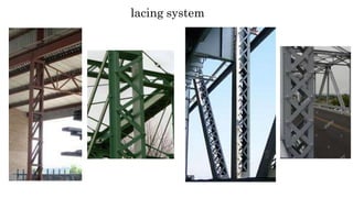
lacing and battening .pptx
- 2. There are two types of lacing system. 1. Single lacing system 2. Double lacing system
- 3. The compression member comprising two main components laced and tied should, where practicable, have a radius of gyration about the axis perpendicular to the plane of lacing not less than the radius of gyration at right angles to that axis. The lacing system should not be varied throughout the length of the strut as far as practicable. Cross (except tie plates) should not be provided along the length of the column with lacing system, unless all forces resulting from deformation of column members are calculated and provided for in the lacing and its fastening. The single-laced systems on opposite sides of the main components should preferably be in the same direction so that one system is the shadow of the other. Laced compression members should be provided with tie plates at the ends of the lacing system and at points where the lacing system are interrupted. The tie plates should be designed by the same method as followed for battens.
- 4. (1)Angle of inclination(θ): (cl. 7.6.4) For single or double lacing system, θ = 40◦ to 70 ͦ To the axis of the built up member normally,=45 is taken (2) Slendernes ratio(kL/r) : (cl. 7.6.5.1) KL/r for each component of column, should not be gretear than 50. or kL/r not greater than 0.7 x most favourable slenderness ratio of the member as a whole The slenderness ratio of lacing shall not exceed 145 (cl. 7.6.6.3)
- 5. (3) effective length of lacing (le) : For bolted connection : For single lacing, le = L For double lacing, le = 0.7 L Where, L = distance between the inner end fastner In welded connection : Le = 0.7 * distance between the inner ends of welds (4)width of lacing bars(b) : minimum width of lacing bar, b = 3d Where, D = nominal diameter of bolt
- 6. (5) Thickness of lacing (t) : (cl. 7.6.3) (cl. 7.6.6.1) For single lacing, t > Le/40 For double lacing, t > Le/60 (6) Transvers shear (Vt) : Vt= 2.5% of the axial force in the column. This force shall be divided equally among the lacing systems in parallel Planes. For double lacing F=Vt/4 sin
- 7. (7) Check for compressive strength For lacing using Le/r min and fy = 250 Mpa Find Fcd from IS: 800, table -9 (c) For rectangular section buckling class is “c”. Compressive load carrying capacity of lacing Pd = (b * t) * fcd If (b *t )* fcd > F(axial force n lacing) …. OK b*t = area of lacing i.e. pd > F …. OK
- 8. (8) check for tensile strength: tensile strength of lacing flat is Td = 0.9 (b-d)t fu /ϒ or fy.Ag/ ϒmo Which ever is les { Is: 800 If Td > F…….Ok 6.3.1 pg 32 } (9) End connection : For case (a) : Resultant on force on bolt = R = F No of bolt required = F/bolt value For case (b) : Resultant on force on bolt = R =2Fcos No of bolt required = 2𝐹 𝑐𝑜𝑠θ 𝑏𝑜𝑙𝑡 𝑣𝑎𝑙𝑢𝑒 s. cl. θ (cl. For 16 dia. Bolt strength is single shear= 29 kN For 20 dia. Bolt strength is single shear= 45.3 kN Strength of bolt in bearing =2.5 kb.d.t.fu 10.3.4)
- 9. (10) Overlap: In case of welded connection, the amount of overlap measured along either edge of lacing bar shall not be less than , four times the thickness of thelacing bar or the thickness of the element of main member, whichever is less.
- 10. Compression member can also be built up intermediate horizontal connecting plates or angle connecting two or four elements of column .these horizontal connecting plates are called battens The battens shall be placed opposite to each other at each end of the member and at point where the member is stayed in it length and as for as practicable , be spaced and proportioned uniformly throughout. The number of battens shall be such that the member is devided into not less than three bays within its actual length
- 11. (IS : 800, cl. 7.2.2, P.51) (1)The number of battens shall be such that the member is divided into not less than three bays. (2) Battens shall be designed to resist , simultaneous
- 12. Longitudinal shear Vb = Vt. C/Ns And Moment M=Vt.C/2N Where, Vt = transverse shear force C = distance between centre to centre of battens longitudinally . N = number of parallel planes of battens (2 usually) S= Minimum transverse distance between the centroid of the bolt/ rivet group / welding.
- 13. (3) Slenderness ratio : (cl. 7.7.1.4) 𝑟 the effective slenderness ratio (𝑘𝐿 )e of battenced column shall be taken as 1.1times 𝑘𝐿 𝑟 the ( )o, the maximum actual slenderness ratio of the column, to account forshear (cl. 7.7.3) deformation effects. (4) Spacing of battens (C) : For any component of column (i) 𝑐 (ii) 𝑟 𝑚𝑖𝑛 𝑐 𝑟 𝑚𝑖𝑛 should not greater than 50 should not greater than 0.7 * kL/r of built up column (about z-z axis) (5) Thickness of battens (t) : (cl. 7.7.2.4) t > 𝐿𝑏 50 where Lb = Distance between the inner most connecting line of bolts, perpendicular to the main member
- 14. (6) Effective Depth of battens (de) : (cl 7.7.2.3) de > 3/4 *a ……… for intermediate battens de > a,……. For end batten de > 2b , ………. For any battens where de = effective depth of battens = distance between outermost bolts longitudinally a = distance between centroid of the main member b = width of one member Overall depth of battens D = de + (2 * end distance)
- 15. (7) transverse shear (Vt) : (cl. 7.7.2.1) Vt = 2.5 % of the factored axial column load (8) Ovrlap (cl. 7.7.4.1) for welded connection, the overlap shall be not less than four times the thickness of the battens It should be noted that the battens columns have least resistance to shear compared to column with lacings
- 16. the minimum thickness of rectangular slab bases , supporting columns under axial compression shall be ts =√(2.5 w (a2 - 0.3b2) ϒmo/fy) > tf Where ts = thickness of slab base w = uniform pressure below the base a,b = larger and smaller projection, respectively of slab base beyond the column tf = flange thickness of compression member
- 17. Design a slab base foundation for a column ISHB 350 to carry a factored axial load of 1200 KN. Assume fe 410 grade steel and M25 concrete. take safe bearing capacity of soil as 200 kN/m2 Solution : For steel fe 410 For m 25 concrete, fy = 250 N/mm2 fck = 25 N/mm2 FOR ISHB 350 COLUMN h = 350 mm Bf =250 mm Tf = 11.6mm Tw= 8.3 mm
- 18. (a) Area of base plate : {IS 800 -2007 CL. 7.4.1 P.46 } pu = 120 kn ( factored load ) bearing strength of concrete = 0.6 fck = 0.6 * 25 = 15 N/mm 2 area of base plate : p = u 𝑏𝑒𝑎𝑟𝑖𝑛𝑔 𝑠𝑡𝑟𝑒𝑛𝑔𝑡ℎ 𝑜𝑓 𝑐𝑜𝑛𝑐𝑟𝑒𝑡𝑒 A = 1200∗103 15 = 80,000 mm2 size of built up column b = 350 mm d = bf =250mm
- 19. a =larger projection = 50 mm b = smaller projection = 50 mm W = uniform pressure on base plate 3 =1200 ∗10 450 ∗350 = 7.62 n/ mm2 thickness of base plate =t provide 50 mm equal projection all around the column width of plate Bp = 350 + 50 + 50 = 450 mm Dp = 250 + 50 +50 = 350 mm Use base plate of size 450 mm* 350 mm Gross area of base plate provided = 450 * 350 = 157500 mm2 ( B ) THICKNESS OF BASE PLATE :
- 20. (C) WELD CONNECTING COLUM TO BASE PLATE : Use a 6 mm fillet weld all around the colum section to hold the base plate in position total length available for welding along the periphery of ISHB 350 , there are 12 ends for ISHB DEDUCTION = 12* 2S =12 * 2 * 6 = 144 mm effective length of weld available = 1683.4 – 144 = 1539.4
- 21. capacity of weld per mm length = 0.7 s * fwd = 0.7 * 6 * 189 = 793.8 n/mm = 0.7938 KN/mm required length of weld = 1200 0.7938 = 1512 mm < 1539.4 mm 6 mm weld is adequate .
- 22. (D) SIZE OF CONCRETE BLOCK : Axial load on column =120 kN(factored load) Working load =1200/1.5=800kN Add 10% as self weight of concrete block =80KN Total load =800+80=880 kN Area of concrete block required =Total load /S.B.C. of soil =880/200 =4.4m2
- 23. Concrete block is designed for working load Consider rectangular concrete block with equal projection beyond base plate. Let, X= projection of concrete block Area of concrete block =L*B 4.4=(0.45+2x) *(0.35 + 2x) 4.4=0.1575 + 0.7x +0.9x + 4x2 4x2 + 1.6 x – 4.2425 = 0 Solving it, x=0.849 m Using calculator , say x= 0.85 m
- 24. L=0.45 + 2 * 0.85 = 2.15m B=0.35 + 2*0.85 = 2.05m Area of concrete block provide = 2.15 * 2.05 =4.407m2 > 4..4 m2……OK Assumme angle of dispersion =45° Depth of concrete block = d = x = 0.85 m
- 25. column splice: A joint when provided in the length of column to get to required length it I called column splice. If a column is loaded axially, theoretically no splice is required. Compression will be transmitted by direct bearing, and column sections could be rested one on top of each other. How ever , In practice the load on column is never truely axial and the real column has to resist bending due to this eccentrically applied load. In addition , the column may be subjected to bending moments. Also, the bearing surface of the adjacent sections can never be machined to perfection.
- 26. Design of column spices: The steps inn the design of splices are: 1. Determine the nature of loads to which the splice is subjected. The splice may be subjected to axial compressive load, bending moment and shear force. 2. For axial compressive load the splice plates are provided on the flanges of the two columns. if the ends of columns are milled/machined, the splice is designed only to keep the column in position and to carry tension due to the bending moment. In this case splice plate is designed to carry 50% of the axial load and tension due to B.M. if the ends of column are not milled/machined, the splice and connections are designed to resist the total axial load and tension, if any.
- 27. 3. Load due to axial load for machined ends of column, Pul= load on splice due to axial factored load Pu on the column. 𝑃𝑢 4 = (total load on splice plates =𝑃𝑢 2 2 but load on each splice plate = 𝑃𝑢 ) For non-machined ends of column, Pul = 𝑃𝑢 2 4. Load due to bending moment Pu2 = 𝑀 𝑢 𝑙𝑒𝑣𝑒𝑟 𝑎𝑟𝑚 = 𝑀𝑢 𝑎 Where, a = lever arm = c/c distance of two splice plates.
- 28. 5. Column splice plates are assumed to act as short column (with zero slenderness). Hence, the plates will be subjected to yield stress (fy). fcd= 𝑓 𝑦 1.10 6. The cross-sectional area of splice plaate(A) A= 𝑃 𝑢 𝑓𝑐 𝑑 Pu= Pul + Pu2 7. The width of splice plate is kept equal to the width of the column flange. thickness of splice plate= 𝐴 𝑤𝑖𝑑𝑡ℎ 𝑜𝑓 𝑠𝑝𝑙𝑖𝑐𝑒 𝑝𝑙𝑎𝑡𝑒 For column exposed to weather , the thickness of splice should not Be less than 6 mm.
- 29. 8. Nominal diameter of bolts for connection is assumed. 9.When the bearing plates are to provided to join two columns of unequal • sizes: - The bearing plate may be assumed as short beam to transmit t • to the lower column. - Axial load of the column is assumed to be taken by flangesonly. shown in figure • Maximum B.M in bearing plate: No. of bolts=𝑇𝑜𝑡𝑎𝑙 𝑙𝑜𝑎𝑑 𝑜𝑛 𝑠𝑝𝑙𝑖𝑐𝑒 𝑝𝑙𝑎𝑡𝑒 𝑠𝑡𝑟𝑒𝑛𝑔𝑡ℎ 𝑜𝑓 𝑜𝑛𝑒 𝑏𝑜𝑙𝑡 he axial load 2 M=𝑃𝑢 *a1
- 30. The length and width of the bearing plates are kept equal to the size of the lower storey column. Thickness of bearing plate, M= fbs * Z Where , fbs= design bending stress = 𝑓𝑦 250 1.10 1.10 = = 227.27 N/𝑚𝑚2 2 Z = 𝑏𝑡 6
- 31. 10. The web splice plates are designed to resist maximum shear force. 11. If packing are provided between the splice plate and column flange and more than 6mm in thickness, the design shear capacity of the bolts is reduced as per cl. 10.3.3.3 of IS : 800-2007.
- 32. A column section ISHB 250@ 500.3 N/m is carrying a factored load of 600 kN. Design a suitable column splice. Use 16 Ø 4.6 grade bolts and steel of grade Fe 410. Solution.. For 4.6 grade bolts, Fub =400 N/mm2 For – fe 410 plate fu = 410 N/mm2 fy = 250 N/mm2 For column ISHB 250 @ 50.3 N/m bf = 250 mm tf = 9.7 mm
- 33. Assume ends of columns are miled /machined for complete bearing. Therefore , splice plate are designed for 50 % of axial load of column . load on each splice plate , pu1 =𝑝 𝑢 4 = 600 4 = 150 KN 𝑓𝑦 ɣ𝑚0 1.10 Fcd = 250 = 227.27 N/mm2
- 34. Area of splice plate requride = 150 ∗103 = 660 mm2 227.27 width of splice plate should be equal to the width of the column flange . b = 250 mm thickness of splice plate, 𝑏 250 t = 𝑎𝑟𝑒𝑎 = 660 = 2.54 mm provide 6 mm thick splice plate as colum may be exposed to weather . For 16 mm dia , 4.6 grade bolts strength of bolt in single shear = 29 KN
- 35. Stength of bolt in bearing ( on 6 mm plate ) = 2.5 kb . D .t .fu /ɣ𝑚𝑏 = 2.5 * 1* 16 * 6 * *400/1.25 = 76800 N = 76.8 KN bolt value = 29 KN N0 0f bolt required =150/29=5.17 say 6 nos. Provide 16 mm dia , 6 bolt on each side of the splice (joint) in two vertical raws to connect splice plate with column flangers. Minimum pitch = 2.5 d = 2.5* 16 = 40 mm
- 36. Provide pitch = 50 mm Edge distance = 1.5 d0 =1.5 *18 =27 mm provide 30 mm Depth of splice plate =(4 * 50) +(4*30) =320 mm Provide splice plate 320*250*6mm 0n column flanges.