SlideShare uma empresa Scribd logo
1 de 21
Baixar para ler offline
1 | P a g e Mandeep Jamwal
Communication system
Introduction
A primary distinctive feature modern civilization is the availability and widespread utilization of communication or
telecommunication: the process of transmission and reception of information over extended distances. The information
exchanged may be in the form of a speech or written words, music, diagrams, numbers, pictures or computer data’s
communication plays such an important role in the development that it is regarded as a basic resource like minerals and
energy,
REPRESENTING INFORMATION: SIGNAL
Information converted into electrical form and suitable for transmission is called a signal.
Signals are of two types.
(a) Analog signal: A signal in which information is changed to a voltage or current that varies continuously and
smoothly over a range of values is called and analog signal.
The waveform of the voltage of current, i.e., its variation with time, represents the information and is an analogue of
it.
For example, the loudness and pitch of a sound determine the amplitude and frequency, respectively of the
waveform of the voltage produced by a microphone on which the sound falls. Analog electronics deals with the
processing of analog signals, e.g., in radio and television systems.
(b) Digital signal: A signal which can take only discrete stepwise values is called a digital signal.
In a digital signal, information is converted into pulses produced by switching electricity on or off in switching-
type circuits, e..g, logic gates.
In a simple circuit, data can be sent by the ‘dots’ and ‘dashes’ of the Morse code by closing the switch for a short or
a longer time. In fig (b), the letter ‘A’(. -) is shown
Digital systems such as computers handle all information (not just numbers) in the binary code with the digits 1 and
0 being represented by ‘high’ and ‘low’ voltages respectively. It follows that if words are to be processed, a pattern
of Is (plural of 1) and 0s (plural of 0) has to be agreed for the 26 letters of the alphabet. A 5-bit code has 25
(32)
variations, i.e., from 00000 to 11111, which would be enough. However, many digital systems use 8-bit words, i.e.,
2 | P a g e Mandeep Jamwal
bytes. The American Standard at code for information Interchange (ASCII) is an 8-bit code that allows 28
(256)
characters to be coded in binary. This is adequate for all letters of the alphabet (capital and small), the numbers 0 to
9, punctuation marks and other symbols fig (c), shows one 8-bit pulse, which represents the letter capital S in
ASCII.
Advantage of Digital Signals
Information in digital form has certain important advantages over that in analog form in spite of the fact that
many input devices (e.g., microphones, thermostats) produce analog signals. The following are the reasons for this.
(i) Digital signals can be transmitted over long distance without error because of their ability to cope up with
noise.
(ii) Digital signals fit in with modern technology and can be used with both telecommunication and data
processing equipment.
(iii) Digital systems are easier to design and build (mostly from logic gates) and can be integrated on a single
silicon chip.
BASIC COMMUNICAITON TERMINOLOGY: TEMINOLOGY OF COMMUNICAITON
Apart from the terms we have already used, the following additional ones of great help to understood the
principle of communication.
(i) Transducer: an electrical transducer is a device that converts some physical variable like pressure,
displacement, force, temperature etc. into corresponding variations in the electrical signal at its output.
(ii) Noise: Stray unwanted voltages and currents which disturb the transmission and processing of message
signals constitute noise. The noise distorts the waveform and causes ‘hiss’ and ‘hum’ in loudspeakers. The
source generating noise may be coated inside (the random motion of the carbon granules in a telephone
mouthpiece) or outside the system (sparking of a car ignition system.)
(iii) Transmitter: it process the incoming message signal and makes it suitable for transmission though a
channel and subsequent reception.
(iv) Receiver: It extracts the desired message signals from the received signals at the output of the channel.
(v) Antenna: an antenna (or aerial) radiates or receives radio waves. Any conductor can act an antenna but
proper design is necessary for maximum efficiency. The dipole antenna consists of two vertical or
horizontal conducting rod or wires,
Each of length ߣ/4, where ߣis the wavelength of the wave to be emitted and is centre fed. A dipole antenna
is frequently used for frequencies below 30 MHz. Wheereas transmitting aerials may handle many kW of r f
power, receiving aerials, though basically similar, deal with only a few mV due to voltages (of a few mV)
an currents induced in the bypassing radio waves.
3 | P a g e Mandeep Jamwal
(vi) Attenuation: The weakening of a signal as it propagates through a medium is called attenuation.
(vii) Amplification: The process of increasing the amplitude and consequently the strength of a signal is called
amplification and the electronic circuit that performs this task is called an amplifier. Amplification is
necessary to compensate the loss in strength of the signal in communication. The energy required for this
purpose is supplied by a dc power source. Amplification is done at a place between the source and the
receptor of information wherever the signal becomes weaker than the required strength.
(viii) Range: The largest distance between the source and the receptor of information (i.e., destination) upto
which the signal has sufficient strength is called the range of the signal.
(ix) Bandwidth: The range of frequencies a signal occupies or over which an equipment operates is called
bandwidth.
(x) Modulation: the process of mixing low frequency signal (called message signal) and a high frequency
signal (called carrier signal) is called modulation.
(xi) Demodulation or Detection: The process of recovering the message signal from the high frequency signal
received by the receive is called demodulation or detection.
(xii) Baseband Signals: Practically, no message signal is of single frequency. In fact, a message signal
representing the original signal delivered by the source of information, consist of a band of frequencies. As
such, these are called base band signals.
(xiii) Repeater: In communication, range is of great importance. To extend the range, use is made of a repeater,
which is a combination of a receiver and a transmitter. A repeater picks up the signal from the transmitter,
amplifier it and then retransmits to the next receiver as shown in fig.
A communication satellite is in fact a repeater station in geostationary orbit.
(xiv) Distortion: The extent to which a system fails to reproduce accurately at its output the characteristics of the
input is called distortion. We are presently concerned with electrical distortion in which the waveform of
voltage of current is modified by a transmission system or network. It involves the introduction of features
that do not appear in the original signal or the suppression or modification of features that are present in the
original signal.
ELEMENTS OF A COMMUNICAITON SYSTEM
All communication system have three essential components: namely transmitter, receiver and channel.
4 | P a g e Mandeep Jamwal
(i) Transmitter: It converts the message signal produced by the source of information into a form suitable for
transmission and reception. A transmitter may have to be coupled with an electrical transducer in case the
output of the information source is a non electrical signal, e.g., a voice signal.
(ii) Channel: It is the link between the transmitter and the receiver. The channel ay be in the form of wires or
cable s connecting the transmitter or the receiver for it may be wireless. As a transmitted signal propagates
along the channel, it is weakened and gets distorted due to channel imperfection. It also packs up noise.
(iii) Receiver: It receives the transmitted signal, extracts the original message signal from it and then delivers it
to the receptor (i.e., user of information) after reconstruction (i.e, after eliminating noise and distortion).
MODES OF COMMUNICAITON
There are two basic modes of communication.
(i) Point to point communication: It is the mode in which communication takes place via a link between a
single transmitter and a receiver, e.g., telephonic conversation.
(ii) Broadcast: It is the mode in which communication takes place via a link between a single transmitter and a
large number of receivers, e.g., radio and television.
BANWIDTH (BW) OF A SIGNAL
The range of frequencies occupied by a signal is called the bandwidth of the signal.
Different types of signals (voice, music, picture, computer date) have different bandwidths. The
type of communication system needed for transmission and reception for a given signal depends upon its BW.
(a) For intelligible speech signals, a frequency range of 300 Hz to 3100 Hz is considered adequate. Thus for
transmission of a speech signal, a bandwidth of 2800 Hz (3100 Hz- 300 Hz) is required. Thus is o in the case of
telephonic communication.
(b) For high quality musical sound signals, where musical instruments produce high frequencies, a bandwidth of 20
kHz is required, for transmission of such signals (audible range extends from 20 Hz to 20 kHz)
(c) For video singles, which transmit pictures, a bandwidth of 4.2 MHz is required for their transmission.
(d) TV signals, which contain both audio (voice) and video (picture) signals, a bandwidth of 6 MHz is usually
allotted for their transmission.
Note: digital signals are in the form of rectangular waves. It can be shown that a rectangular wave is due to
superimposition of sinusoidal waves of frequencies v0, 2v0, 3v0 …. ∞ (where v0 is the fundamental frequency),
which implies an infinite bandwidth.
BANDWIDTH OF A TRANSMITTING MEDIUM
The range of frequencies offered by a transmitting medium is called the bandwidth of the transmitting medium.
5 | P a g e Mandeep Jamwal
The bandwidths of some of the commonly used transmitting media are given below:
(i) Coaxial cable : = 750 MHz
(ii) Free space : = a few kHz to a few GHz
(iii) Optical fibre : In excess of 100 GHz.
PROPAGATION OF RADIO WAVES
Radio waves are a member of the electromagnetic family of waves. They are energy carriers which travel at eh peed
of light, their frequency v and wavelength ߣbeign related by te equation c = v ߣ.
If ߣ = 300 m.v =
௖
ఒ
=
ଷ.଴ ௑ ଵ଴ఴ ௠ /௦
ଷ଴଴௠
= 106
Hz = 1 MHz
The smaller the ߣ, the arger the v. Radio wave can be described either by their frequency or their wavelength, but the former
is more fundamental sice unlike ߣ(and v). v does not change when the wave travels from one medium to another. They have
frequencies extending from 30 kHz upwards and are grouped into band along with their uses in Table.
Frequency band Some uses
1. Low frequency (LF)
(30 kHz – 300 kHz)
2. Medium frequency (MF) (300 kHz – 3
MHz)
3. High frequency (HF)
(3 MHz – 30 MHz)
4. Very high frequency (VHF) (30 MHz –
300 MHz)
5. Ultra high frequency (UHF) (300 MHz – 3
GHz)
6. Microwave frequency (Above 3 GHz)
Long wave radio and communication over large
distance
Medium wave, local and distant radio
Short wave radio and communication , amateur and
CB radio
TV, F radio, police, meteorology devices
TV (bands 4 and 5), aircraft lading systems
Radar, communication satellites, mobile telephones
and TV links
Radio wave can travel from the transiting to recovering antenna in one or more of three different ways depending
upon their frequency. These modes of wave propagation have been discussed in subsequent articles.
GROUND WAVE: SURFACE WAVE
In ground wave propagation, the radio waves are guided by the Earth and travel along its curved surface from the
transmitter to the receiver.
Ground wave propagation has been shown in fig.
6 | P a g e Mandeep Jamwal
Some important characteristic of ground waves are as follows.
(i) Ground waves are greatly affected by the electrical properties of the ground over which they move. Poor
conductors such as and absorb more energy from these waves than water.
(ii) The range of coverage depends on the transmitted power and frequency.
(iii) Ground wave propagation is useful only at low frequency since high frequency waves are greatly absorbed by
the ground.
(iv) The range of these waves is about 1500 km at low frequencies (long waves). AM radio broadcast in the medium
frequency band (meant for local areas) is carried out mainly by ground wave.
(v) The range of these waves is much less for VHF due to their increased absorption at higher frequency.
(vi) Ground wave transmission has the merit of being extremely reliable, irrespective of atmospheric condition.
SKY WAVE: IONOSPHERIC WAVE
In sky wave propagation, the radio wave travels skywards and if its frequency is
below certain critical frequency (typically 30 MHz) , it is returned to the Earth by the ionosphere.
The sky wave below critical frequency travels from the transiting antenna (T) to the
receiving antenna (A) via ionosphere.
The ionosphere consist of layers of air molecules (the D, E , F1, F2 layers), stretching from about 65 km to 400
km, which have become positively charged through the removal of electrons by the Sun’s ultraviolet radiation. On
striking the earth, the sky wave bunches back to the ionosphere where it is again gradually refracted and returned
earthwards as if by ‘ reflection’ . this continues until it is completely attenuated. The critical frequency varies with the
time of day and seasons.
Following are the important features of sky waves.
(i) Sky wave of low, medium and high frequencies (LF, MF, HF) i.e., below 30 MHz can travel thousand of km.
(ii) Sky waves of very high frequency (VHF), an above, i.e., above 30 MHz, usually pass through the ionosphere
into outer space.
(iii) Short wave (3MHz, to 30 MHz) transmission around the globe takes place by sky waves via successive
reflections at the Earth’s surface and the ionosphere.
7 | P a g e Mandeep Jamwal
(iv) Sky wave transmission is an elusive and tricky business as it is subject to fading and disappearing of signals.
This is due to erratic changes in the ionosphere with seasons, night and day and atmospheric condition. But in
spite of its, if it is the primary means of around-the world short wave communication.
SPACE WAVE
In space wave propagation , the radio wave travels in a straight line from transmitting antenna to the
receiving antenna.
Some of the salient features of the space wave are as follows.
(i) Since a space wave travels within the first 15 km over the surface of the Earth, i.e., in the Earth’s troposphere,
their propagation is also called tropospherical propagation.
(ii) A space wave is usually made up of two components:
(a) The direct or line- of-sight wave fro the transmitting to the receiving antenna
(b) The ground reflected wave travelling from the transmitting antenna to the Earth and reflected to the
receiving antenna.
(iii) For VHF, UHF and microwave signals, only the space wave, giving the line-of sight (LOS) propagation, is
effective.
(iv) As the space wave does not undergo continuous absorption by the Earth’s surface, it can cover greater distance
than the ground wave.
(v) A range of upto 150 km is possible on Earth if the transmitting aerials are on high ground and there are no
intervening obstacles such as hills, buildings or trees.
(vi) Space waves are used for satellite communications, television broadcast and microwave links.
(vii) In general, space wave propagation is affected by weather conditions in the lower atmosphere and the subject to
changes with variation in temperature, humidity an air pressure.
RANGE OF A TRANSMITTING ANTENNA: RADIO HORZON
In fig, AP is the height (hT) of the transmitting tower, if the transmitting antenna is at A, then signals transmitted by it
cannot reach beyond the places B and C on Earth, which are obtained by drawing tangents from A to the Earth’s
surface.
8 | P a g e Mandeep Jamwal
Clearly, PB = PC = dr(radio horizon of the transmitter)
In ΔACO,
AC2
+ OC2
= AO2
Or ்݀
ଶ
+ R2
= (R + hT)2
(as AC = PC = DT)
Or ்݀
ଶ
+ R2
+ R2
+ ℎ்
ଶ
= 2 RhT (1 +
௛೅
ଶோ
Since hT << R, (hT/2R) can be neglected
Clearly, ்݀
ଶ
= 2RhT
Or dT = ඥ2ܴℎ் …(1)
RANGE OF APCE WAVE PROPAGATION ON EARTH’S SURFACE
In fig, hT and hR represent the heights of the transiting and receiving antennas.
9 | P a g e Mandeep Jamwal
When the space wave takes from the transmitting to receiving antennas without
being obstructed by the curvature of the Earth, the line of sight between the two antennas touches the horizon(H).
If dT and dR are the distances( called the radio horizons) of the transmitting and receiving antennas from H, then
DT = ඥ2ܴℎ் and dR = ඥ2ܴℎோ
Clearly, maximum line of sight distance between the two antennas, i.e.,
DM = dT + dR = ඥ2ܴℎ் + ඥ2ܴℎோ …(1)
Obviously, dM is the range of space wave propagating between the two antennas on the Earth.
MODULATION
The process of superimposing the low frequency message signal on a high frequency wave (called the carrier wave)
is called modulation.
The low frequency message signal is called modulating signal or modulating wave and the resultant of modulating
wave and carrier wave is called modulated carrier wave or the modulated signal.
Need for Modulation
Although audio frequency signals may be transmitted directly by cable, in general, and certainly in radio and TV, a
carrier wave is required as is clear from the following arguments.
(a) Size of the antenna: for transmitting a signal, we need an antenna (also called an aerial) which should have a size
comparable to the wavelength (ߣ) (or at least ~ ߣ/4) of th signal. For eample, in case of a signal (an e.m. wave
travelling with speed c = 3 X 10⁵
k/s) of frequency 20 kHz,
ߣ =
௖
௩
=
ଷ௑ ଵ଴ఱ ௞௠ / ௦
ଶ଴ ௑ ଵ଴య / ௦
= 15 km
Obviously, this is an impossible size for an antenna. Hence, the necessity of carrier wave (of high frequency) to reduce the
size of the antenna to transmit the signal.
(b) Effective power radiated by an antenna: it can be shown that the power (P) emitted by a linear antenna of length I
while radiating e m waves of wavelength ߣis given by
P ∝ (
ଵ
ఒ
)2
For a baseband signal of low frequency, wavelength (ߣ) is large and as such P is also small. Obviously, such a
signal will to be able to travel long distances. Hence, the need for high frequency waves (carrier waves) to increase
P to carry the baseband signal over long distances.
(c) Mixing up of baseband signals from different transmitters: When different transmitters are transmitting signals will
get mixed up and we will not be able to distinguish between them. To overcome this difficulty, a unique carrier
frequency is allotted to each signal for its transmission. Thus, modulation makes it possible to use discrete non
interfering frequency channels for carrying on a number of simultaneous transmissions in a locality.
TYPES OF MUDULATION
A carrier wave may be sinusoidal (continuous) or in the form of a pulse. Both types of wave can be
modulated. A sinusoidal carrier wave can be represented as:
c(t)= Ac sin (߱c t + φ)
10 | P a g e Mandeep Jamwal
Where c(t) = strength (voltage or current) of carrier waves at time t
Ac = amplitude of the carrier wave
߱c ( = 2ߨvc) = angular frequency of the carrier wave
φ = initial phase of the carrier
in modulation, any of these three parameters (Ac , ߱c and φ) of the carrier is changed by the modulating signal (i.e.,
information or message signal).
Accordingly, modulation of the sinusoidal carrier wave can be carried out in the following three ways.
(a) Amplitude Modulation (AM): In amplitude modulation, the amplitude of the carrier is varied by the modulating
signal and the change in amplitude form the unmodulated value is directly proportional to the instantaneous value of
the modulating signal it is independent of its frequency. This is represented in fig.
(b) Frequency Modulation (FM): In frequency modulation, the instantaneous frequency of the carrier is varied by the
modulating signal. The instantaneous deviation of frequency from then modulated value is directly proportional to
the instantaneous value of the modulating signal but is independent of its frequency. This is represented in fig.
(c) Phase modulation: in phase modulation, the instantaneous phase angle of the carrier is varied by the modulating
signal. The instantaneous deviation of the phase angle from the unmodulatd value is directly proportional to he
instantaneous value of the modulating signal but is independent of its frequency.
AMPLITUDE MODULATION (AM)
In amplitude modulation, the information signal (modulating signal) is used to vary the amplitude of the carrier so
that it follows the wave shape of the information signal.
Let the carrier wave (assume sinusoidal) be represented by
C(t) = Ac sin ߱ct …(1)
11 | P a g e Mandeep Jamwal
Further, for simplicity, let us suppose that the modulating signal is also sinusoidal and is represent by
M(t) =Am sin ߱mt …(2)
Where ߱m is the angular frequency of the modulating signal.
In practice ߱m is small compared to ߱c. In radio transmission, ߱m/ ߱c = 1/1000,
The amplitude modulated (AM) carrier signal is given by
Cm (t) = (Ac + Am sin ߱m t) sin ߱ct
or cm(t) = Ac (1 + µ sin ߱mt) sin ߱ct …(3)
where µ =
஺೘
஺೎
…(4)
here, µ is called modulation index, modulation factor or depth of modulation.
In practice to avoid distortion, µ< 1.
Modulation Index in term of Amplitude of AM Carrier Wave
From eqn. (3), amplitude of AM carrier wave,
M = Ac (1 +µ sin ߱mt) …(5)
Maximum value of M (when sin ߱m t = +1) i.e.,
M1 = Ac (1 + µ) … (6)
Minimum value of M (when sin ߱m t = -1), i.e.,
M2 = Ac (1 - µ) …(7)
Thus, M1 + M2 = 2Ac
And M1 – M2 = 2µ Ac …(8)
Clearly, µ=
ெ భ ି ெమ
ெ భ ି ெ మ
…(9)
From eqn. (3).
Cm(t) = Ac sin ߱c t + µAc sin ߱c t sin ߱m t
= Ac sin ߱c t +
µ஺೎
ଶ
cos (߱c - ߱m) t -
µ஺೎
ଶ
cos (߱c + ߱m) t …(10)
(as sin A sin B =
ଵ
ଶ
[{cos (A – B) – cos (A + B)}])
Frequency Spectrum of AM Carrier Wave
From eqn. (10), it is clear that AM carrier wave, with sinusoidal modulation, consists of three components.
(i) Original carrier wave of amplitude Ac and frequency vc = ߱c /2ߨ.
12 | P a g e Mandeep Jamwal
(ii) A wave of amplitude µAc/2 and frequency (vc – vm) = (߱ = ߱m) /2ߨ. This frequency I called the Lower Side
Frequency (LSF).
(iii) A wave of amplitude of µAc/2 but of frequency (vc + vm) = (߱c + ߱m) /2ߨ. This frequency is called the Uper
Side Frequency (USF).
Fig (a) or (b), which gives the amplitudes of these frequency components is known as the frequency spectrum.
It is clear that information (i.e., modulating signal) is contained in side frequency components and not the
carrier component.
The difference between USF and LSF [i.e., (vc + v) – (vc – vm) is called the bandwidth and is
equal to 2vm. Thus.
In case of modulation by a single frequency, the BW is twice the
modulation frequency.
PRODUCTION AN TRANSISSION OF AM WAVE
Production of AM Wave
There are variety of method s to produce an AM wave. A block diagram of a simple modulator for obtaining AM
wave, using a square-law device, is shown in fig
Let the modulating signal and the carrier be represented by
13 | P a g e Mandeep Jamwal
M(t) = Am sin ߱mt …(1)
And c(t) = Ac sin ߱ct …(2)
If x(t) is the resultant signal obtained by adding m(t) and c(t), then
X(t) = m (t) + c(t) = Am sin ߱m t + Ac sin ߱c t …(3)
Let x(t) be passed through the square law dive which produces an output y(t) according to the relation
Y(t) = B[x (t)] + C [x(t)]2
…(4)
Where B and C are constants.
Thus, from eqns. (3) and (4),
Y(t) = B [Am sin ߱m t + Ac sin ߱c t]
+ C [‫ܣ‬௠
ଶ
sin2
߱mt + ‫ܣ‬௖
ଶ
sin2
߱c t + 2AmAc sin ߱m t sin ߱c t]
= BAm sin ߱m t + BAc sin ߱c t
+
஼
ଶ
(‫ܣ‬௠
ଶ
+ ‫ܣ‬௖
ଶ
) –
஼஺೘
మ
ଶ
cos2 ߱mt -
஼஺಴
మ
ଶ
cos2 ߱mt
+ CAmAc cos (߱c - ߱m) t – CAmAc cos (߱c + ߱m) t …(5)
[as sin2
A = (1 - cos2
A) and
2 sin A sin B = cos(A – B) – cos (A+B)]
It is obvious from eqn.(5) that output y (t) consists of:
(a) One dc component:
஼
ଶ
(‫ܣ‬௠
ଶ
+ ‫ܣ‬௖
ଶ
)
(b) Six ac components of frequencies: ߱m, 2߱m, ߱c, 2߱c, (߱c - ߱m) and (߱c + ߱m)
When the output [y(t) is passed through band pass filter, centered at ߱c, it rejects dc component (of zero frequency)
and the ac components of frequencies ߱m, 2߱m(which are much lower than ߱c) and 2߱c (which is double than ߱c)
and allows only ߱c, (߱c - ߱m) and (߱c + ߱m). Thus, the output of the band pass filter is given by
Y’(t) = BAc sin ߱c t +CAm Ac cos (߱c - ߱m) t
- CAmAc cos (߱c + ߱m) t …(6)
Clearly, y’ (t) has the same form as that of an AM wave obtained by superimposing a modulating signal of
frequency ߱m on a carrier of frequency ߱c.
Transmission of AM wave
The AM signal generated by the modulator cannot be transmitted as such as it has to be provided necessary power
to cover the desired range. This is done by feeding the AM signal to a power amplifier as shown in fig
14 | P a g e Mandeep Jamwal
The amplified AM signal is fed to an antenna of appropriate size for onward transmission.
DETECTION OF AM WAVE
The process of recovering the modulating signal (i.e., information) from the modulated carrier wave is called
detection and the circuit that performs this function is called a detector.
The complete circuit which receives the modulated carrier, detects the modulating signal and then amplifier it,
is called a receiver. For amplitude and frequency modulated signals, AM and FM receivers are used .
For the sake of simplicity, the basic features of an AM receiver are shown in fig.
Radio frequency (RF) amplifier: The AM wave gets weakened as it propagates through the channel from eh transmitting
antenna to the receiving antenna. To amplify this wave, an RF amplifier is connected to the receiving antenna.
15 | P a g e Mandeep Jamwal
(i) Intermediate Frequency (IF) stage: Before detection, the carrier frequency (߱c) of the AM wave is changed to a
lower frequency (߱c) and amplification is carried out at this frequency. This process is carried out with the help
of an IF stage consisting of a local oscillator, a mixer and an IF amplifier.
(ii) Detector: Its purpose is to detect the envelope of the AM wave because this envelope is the modulating signal
containing the information.
(iii) Audio frequency (AF) amplifier: This amplifier is coupled to the output of ht detector and amplifier the detected
modulating signal which appears at its output.
DETECTOR FOR AM WAVES
We hall describe the function f a detector in some detail with the help of the a block of a detector in some detail with
the help of a block diagram of a detector of AM signal. The IF signal received by the detector contains the angular
frequencies ߱c’, (߱c’ - ߱m) and (߱c’ + ߱m). in order to separate ߱m, i.e., to obtain modulating signal, a simple AM
signal detector is shown in fig.
(i) The AM wave from the IF stage is passed through a rectifier(pn junction diode) which produces a rectified
wave as shown in fig (b).
(ii) The enlope of this rectified wave has a frequency ߱m and is the message signal m(t) as shown in fig (b).
(iii) The rectified signal is passed through an envelope detector (RC parallel network), to retrieve m(t as shown in
fig (C).
INTERNET
The global network of computers is called internet or simply net.
Internet is, in fact, the short form in INTER-NET work which is the interconnected network of all the world
wide main computer (called severs*).
(a) Networking of Computers: When two or more computers share information through connecting wires or by some
wireless means of communication like Wi-Fi**, they are said to be networked.
(i) Local Area Network(LAN): It is a network of computers on a small scale, e.g., within an
16 | P a g e Mandeep Jamwal
educational institution or an office. This network usually has other device like a printer, a scanner etc.
connected to fig (a).
(ii) Wide area network (WAN): It is assemble by connecting various LANs as shown in fig (b)
(iii) Internet: to build internet, we connect various WANs fig (C). The first network of computer.
17 | P a g e Mandeep Jamwal
Advanced research projects agency NETwork (ARPANET) was developed by the US in 1969. In India,
internet was started in November 1998 by VSNL, (Videsh Sanchar Nigam Limited) in Mumbai.
(b) Protocol: A system of digital rules for data exchange within or between computers is called communications
protocol. A standard set of protocols. (TCP) or internet Protocol (IP) are used for the exchange of information
through the internet.
(c) Information on Internet: Information on Internet is provided /available through:
(i) Webpage: It may contain text, images, videos etc. as a document, commonly written in HyperText Markup
Language (HTML) that is accessible through the Interne. The first webpage was created at CERN by Turn
Berners-Lee and put online August 6, 1991.
(ii) Website: It is a central location that contains more than one webpage. In fact, it is a set of related WebPages
typically served from a single web domain. Some web sites require a subscription to access some or all of
their contents.
(iii) World Wide Web (WWW or W3): All publically accessible Websites constitute the World Wide Web
(commonly known as Web).
(d) Applications of Internet: Internet has changed the way most of the world communicates. Out of the endless
applications of internet, we briefly mention the following few:
(i) Internet Surfing: it is an interesting way of searching and viewing information on any topic of interest by
moving on internet from one webpage (or website) to another.
(ii) Electronic mail (email or –e-mail): It is the most used application of Internet and is the cheapest and the
fastest way of sending text written on computers, along with images and videos. For sending an email, a
personal email account with an email-ID or email-address has to be created. An email –ID is protected with
a password and has two parts separated y a sign @ (called at the rate of). For example, the email- ID of the
author of this book surinderalal@gmail.com, provides personal information about the author(his name :
SURINDRA LAL) and gail.com provides information about the server providing him the email facility.
A message stored in an email account can viewed later even when the user is not connected to the internet.
(iii) Electronic banking (e-banking, online banking, virtual banking): it is an electronic payment system that
enables customers to conductor financial transactions on a website operated by the institution. For this
18 | P a g e Mandeep Jamwal
facility a customer with internet access would need to register with the intuition of the eservice and set up
some password for customer verification.
(iv) Electronic shopping (E shopping, e commerce, online shopping): It is a form of electronic commerce which
allows consumers to directly buy goods or services from a seller over the internet using web browser. The
largest of these online retailing corporations are: alibaba, Amazon.com and ebay.
(v) Electronic booking (E-booking, e ticketing): It is an application developed for booking railway tickets,
flight tickets, hotel etc, through the internet.
(vi) Social networking service(social networking site or SNS): It is a platform to build social networks or social
relations among people who share interests, activities , backgrounds or real life connections. A social
network service consists of a representation of each user(often a profile), his or her social links and a variety
of additional services. It allows the users to share their ideas, pictures, events, activities etc. With their
group. The most popular SNS are Facebook, Twitter, Linkedin, Google+, Instagram, Tagged etc.
MOBIEL TELEPHONY
Mobile technology which was conceptualized in 1970, took just a decase to be
finally implemented.
(a) Mobile Phone: it is a phone that can make and receive calls over a radio link while moving around a wide
geographical area. It is, in fact, a handy computer that can be equipped with Internet. A mobile phone is also
called a cellular phone, cell phone or simply a phone or a cell. The first hand hold cell was demonstrated by
Motorola in 1973. Whereas in a walkie-talkie, the radio frequency is used of both sending and receiving signals,
in a mobile, the outgoing and incoming signals use different frequencies and as such, the two individuals can
talk and listen at he same time.
(b) Working Principle of a Mobile phone
(i) The central concept of mobile telephony is to divide the service area into suitable number of cells or
cell zones. To completely cover a given are, use of hexagonal cells is the best possible way. All the
Cells are centered on Mobile telephone switching Office (MTSO) which is basically is telephone exchange
mobile phone calls. Each cell is provided with a low power transmitter, called base stations, which
19 | P a g e Mandeep Jamwal
provides service to a large number of mobile users as each cell antenna ahs a working range of minimum
1.5 to 2 km and maximum upto 48 to 56 km or more m are around it.
(ii) When a mobile user is out of the coverage area of one base station, it gets lined up with another base
station through a process called hand over or hand off. This process is so quick that the mobile user
does not even notice it.
(c) Scientific process of Mobile phone Call
(i) When a mobile number a dialed, an oscillator inside the mobile generates an e.m. wave of a particular
frequency. This information carry e.m. wave is transmitted though the mobile antenna to the antenna of
the cell.
(ii) The cell antenna, in turn, transfers this signal (e.m. wave) to MTSO through the cellular radio network.
(iii) The MTSO computer system identifiers the location (cell) of the mobile phone that has been dialed an
connects it to that.
(iv) The caller mobile on receiving the signal generates through an oscillator the dialer ID and displays it.
The entire process is completed in a few seconds as all the signals are carried by e.m. wave which travel
with the speed of light.
(v) The mobile phone network is also called terrestrial cellular network a mobile phone call is transferred
from dialer cell antenna to MTSO an from MTSO to caller cell antenna only through cell antennae
lying in between.
The process of a mobile phone call from dialer to the called is shown in fig (a)
(d) Mobile phone numbering system
To identify every mobile phone, a SIM (Subscriber Identity Module)car is inserted in it
A SIM is a small IC integrated circuit) chip with a unique number. All SIM cards are issued by mobile operator
companies and their information is provided to the MTSO. Every mobile number in India consists of 10 digits
and has the prefix 9,8 or 7as per the National numbering plan 2003, a mobile number is split as XXXX-
NNNNNN, where XXXX are Network Operator Digits and NNNNNN are the Subscriber Number Digits.
Telecom Regulatory Authority of India, (TRAI) established in 1997 by an act of parliament, regulates the use of
mobile phones in the country.
(c) Mobile Network Generation
With the technology advancing at the rapid rate and the increasing use of mobile phone it becomes essential to
make the mobile phone networks more efficient. To mention the efficiency of these networks, use is made of the
word ‘ Generation’ which is abbreviated as G. whereas 1G were the first generation networks and were base on
analogue radio signals, 2 G were narrow band digital signal base networks. 3G networks increase the data transfer
speed and 4 G are going to provide a high speed internet facility. It is interesting to go through the comparison
between 1G, 2G, 3G and 4G.
1G 2G 3G 4G
2.4 kbps 64 kbps 2000kbps 100,000 kbps
20 | P a g e Mandeep Jamwal
Grasshopper Dog 5storey building Burj Khalifa
South Korea recently announced a $1.5 billion investment in 5G infrastructure upgrades and intends to
rollout a limited trial network by 2017, with full availability by 2020. The 2 G network focused on voice, 3G on
data and 4G on video. The new 5G network will be all abut connection, 7 trillion connect device in the coming
decease and each individual will have at least ten connections.
GLOBAL POSITIONING SYSTEM(GPS)
GPS developed by the US defense department, uses between 24 to 32 medium earth orbit satellites and
transmits signal on microwave frequencies. This enables the GPS to determine their current location, time an
velocity. It is often used by civilian as navigation system. Cell phone incorporate GPS to help their users find their
way and unknown places. Theoretically, a GPS receiver would be able to tell you positive down to the width of
your finger.
India’s first navigational satellite [INSS] was successfully placed in orbit by PSI V -2 on July,2013.
(a) Working principle
To use GPS system of satellite, a GPS device fitted with a transmitter /receiver for sending / receiving signals is
needed to link up with GPS satellite. The unique location of a GPS user is determine by measuring its distance
from at least three GPS satellites. To measure these distance, the time (t) taken by a radio signal to travel from
the device to a satellite and back is recorded by the device (using the relation, D = ct). let D1 D2 and D3 be the
distances of three satellites form the GPS device.
(i) If the user is at a distance D1= from satellite-1, then its location can be anywhere on the circumference
of circle of the radius D1
(ii) If the user is at a distance D2 form the satellite -2 then its location can be either at X or Y, the points
where the circumference of circles of radii D1 and D2 interest.
(iii) if the user is at a distance D3 from the satellite-3 then this location will be at the points of intersection of
circumferences of circles of radii D1 , D2 and D3 form the satellites- 1, 2 and 3 respectively. as is clear
from fig, the user is at the point Y. Obviously, Y gives
the exact location (longitude coordinates) of the GPS device users on the display board.
(iv) If a person is at some height above the earth’s surface then using the distance information from 4 GPS
satellites, even altitude of the user can also be measured.
Note: since all the 24-GPS satellites are in predefine orbits, their locations are precisely determined.
Obviously, it is these known locations of 3 or 4-GPS satellites and their distance to GPS device that enable
the GPS user . its computing device) in locating its longitude coordinates.
21 | P a g e Mandeep Jamwal
(b) Applications of GPs
A GOS system helps in
(i) Navigation on land, water and air’
(ii) Map designing of a location
(iii) Automatic vehicle movements
(iv) Measuring speed of moving objects
(v) Locating change in position of glaciers and mountain heights
(vi) Keeping standard time all over the world
(vii) Tracking animals and birds and studying their movements by attaching SPS device to their bodies
(viii) Airplane traffic movement
(ix) Visually impaired persons in location identification

Mais conteúdo relacionado

Mais procurados

1 . introduction to communication system
1 . introduction to communication system1 . introduction to communication system
1 . introduction to communication systemabhijitjnec
 
Communications
CommunicationsCommunications
CommunicationsWaqas !!!!
 
CBSE Class 12 PCM Sample ebook
CBSE Class 12 PCM Sample ebookCBSE Class 12 PCM Sample ebook
CBSE Class 12 PCM Sample ebookMiso Study
 
CBSE Class 12 PCB Sample ebook
CBSE Class 12 PCB Sample ebookCBSE Class 12 PCB Sample ebook
CBSE Class 12 PCB Sample ebookMiso Study
 
CBSE Class 12 Physics Sample ebook
CBSE Class 12 Physics Sample ebookCBSE Class 12 Physics Sample ebook
CBSE Class 12 Physics Sample ebookMiso Study
 
A Level Physics - Telecommunications
A Level Physics - TelecommunicationsA Level Physics - Telecommunications
A Level Physics - TelecommunicationsJonathan D'Cruz
 
Communication systems v1
Communication systems v1Communication systems v1
Communication systems v1babak danyal
 
Wireless Communication and Networking by WilliamStallings Chap2
Wireless Communication and Networking  by WilliamStallings Chap2Wireless Communication and Networking  by WilliamStallings Chap2
Wireless Communication and Networking by WilliamStallings Chap2Senthil Kanth
 
Communication systems
Communication systemsCommunication systems
Communication systemsMNIT Jaipur
 
Introduction to Communication System
Introduction to Communication SystemIntroduction to Communication System
Introduction to Communication SystemYong Heui Cho
 
telecommunication basic 1
telecommunication basic 1telecommunication basic 1
telecommunication basic 1kasup uditha
 
Introduction to communication systems
Introduction to communication systemsIntroduction to communication systems
Introduction to communication systemsMohsen Sarakbi
 
Communication means
Communication meansCommunication means
Communication meansSunny Tandan
 
Applications of communication system
Applications of communication systemApplications of communication system
Applications of communication systemAmi Goswami
 
Introduction to Communication Systems 3
Introduction to Communication Systems 3Introduction to Communication Systems 3
Introduction to Communication Systems 3slmnsvn
 
Fm transmitter and future radio technology
Fm transmitter and future radio technologyFm transmitter and future radio technology
Fm transmitter and future radio technologyChima Chukwu
 
Engineering plant facilities 10 mechanics building general
Engineering plant facilities 10 mechanics building generalEngineering plant facilities 10 mechanics building general
Engineering plant facilities 10 mechanics building generalLuis Cabrera
 

Mais procurados (20)

Dcn
DcnDcn
Dcn
 
1 . introduction to communication system
1 . introduction to communication system1 . introduction to communication system
1 . introduction to communication system
 
Communications
CommunicationsCommunications
Communications
 
CBSE Class 12 PCM Sample ebook
CBSE Class 12 PCM Sample ebookCBSE Class 12 PCM Sample ebook
CBSE Class 12 PCM Sample ebook
 
CBSE Class 12 PCB Sample ebook
CBSE Class 12 PCB Sample ebookCBSE Class 12 PCB Sample ebook
CBSE Class 12 PCB Sample ebook
 
CBSE Class 12 Physics Sample ebook
CBSE Class 12 Physics Sample ebookCBSE Class 12 Physics Sample ebook
CBSE Class 12 Physics Sample ebook
 
A Level Physics - Telecommunications
A Level Physics - TelecommunicationsA Level Physics - Telecommunications
A Level Physics - Telecommunications
 
Communication systems v1
Communication systems v1Communication systems v1
Communication systems v1
 
Wireless Communication and Networking by WilliamStallings Chap2
Wireless Communication and Networking  by WilliamStallings Chap2Wireless Communication and Networking  by WilliamStallings Chap2
Wireless Communication and Networking by WilliamStallings Chap2
 
Communication systems
Communication systemsCommunication systems
Communication systems
 
Introduction to Communication System
Introduction to Communication SystemIntroduction to Communication System
Introduction to Communication System
 
telecommunication basic 1
telecommunication basic 1telecommunication basic 1
telecommunication basic 1
 
Introduction to communication systems
Introduction to communication systemsIntroduction to communication systems
Introduction to communication systems
 
Communication means
Communication meansCommunication means
Communication means
 
Applications of communication system
Applications of communication systemApplications of communication system
Applications of communication system
 
Introduction to Communication Systems 3
Introduction to Communication Systems 3Introduction to Communication Systems 3
Introduction to Communication Systems 3
 
Fm transmitter and future radio technology
Fm transmitter and future radio technologyFm transmitter and future radio technology
Fm transmitter and future radio technology
 
Engineering plant facilities 10 mechanics building general
Engineering plant facilities 10 mechanics building generalEngineering plant facilities 10 mechanics building general
Engineering plant facilities 10 mechanics building general
 
Communication system
Communication systemCommunication system
Communication system
 
Telecommunications
TelecommunicationsTelecommunications
Telecommunications
 

Semelhante a Communication

Comm introduction
Comm introductionComm introduction
Comm introductionmkazree
 
Introduction to communication system lecture1
Introduction to communication system lecture1Introduction to communication system lecture1
Introduction to communication system lecture1Jumaan Ally Mohamed
 
Communication system 1 chapter 1 ppt
Communication system 1 chapter  1 pptCommunication system 1 chapter  1 ppt
Communication system 1 chapter 1 pptBetelihemMesfin1
 
Comms 1.docx
Comms 1.docxComms 1.docx
Comms 1.docx03211830
 
Communication theory
Communication theoryCommunication theory
Communication theoryVijay Balaji
 
Basic+electronic+interview+questions+and+answers
Basic+electronic+interview+questions+and+answersBasic+electronic+interview+questions+and+answers
Basic+electronic+interview+questions+and+answersMohan Raj
 
Communication channel and networktechnologies.pdf
Communication channel and networktechnologies.pdfCommunication channel and networktechnologies.pdf
Communication channel and networktechnologies.pdfmouizakhan4
 
updated notes cds UNIT 6 and 7 communicationppt.pdf
updated notes cds UNIT 6 and 7 communicationppt.pdfupdated notes cds UNIT 6 and 7 communicationppt.pdf
updated notes cds UNIT 6 and 7 communicationppt.pdfshubhangisonawane6
 
0 lecture 3 wp wireless protocol
0 lecture 3 wp wireless protocol0 lecture 3 wp wireless protocol
0 lecture 3 wp wireless protocolumardanjumamaiwada
 
Wireless communication
Wireless communicationWireless communication
Wireless communicationMukesh Chinta
 
ELEKTRONIKA_KOMUNIKASI_and_GELOMBANG_MIK (2).pptx
ELEKTRONIKA_KOMUNIKASI_and_GELOMBANG_MIK (2).pptxELEKTRONIKA_KOMUNIKASI_and_GELOMBANG_MIK (2).pptx
ELEKTRONIKA_KOMUNIKASI_and_GELOMBANG_MIK (2).pptxzainal968005
 
Ch 01 part 2 - history of telecommunications and regulations
Ch 01    part 2 - history of telecommunications and regulations Ch 01    part 2 - history of telecommunications and regulations
Ch 01 part 2 - history of telecommunications and regulations sakariachromabook
 
Lecture 1 introduction and signals analysis
Lecture 1 introduction and signals analysisLecture 1 introduction and signals analysis
Lecture 1 introduction and signals analysistalhawaqar
 
Introduction to electronic system
Introduction to electronic systemIntroduction to electronic system
Introduction to electronic systemNamit Sood
 

Semelhante a Communication (19)

Comm introduction
Comm introductionComm introduction
Comm introduction
 
Introduction to communication system lecture1
Introduction to communication system lecture1Introduction to communication system lecture1
Introduction to communication system lecture1
 
Communication system 1 chapter 1 ppt
Communication system 1 chapter  1 pptCommunication system 1 chapter  1 ppt
Communication system 1 chapter 1 ppt
 
CLASS 1.pptx
CLASS 1.pptxCLASS 1.pptx
CLASS 1.pptx
 
unit1.pptx
unit1.pptxunit1.pptx
unit1.pptx
 
Comms 1.docx
Comms 1.docxComms 1.docx
Comms 1.docx
 
Communication theory
Communication theoryCommunication theory
Communication theory
 
NETWORKIN2
NETWORKIN2NETWORKIN2
NETWORKIN2
 
Basic+electronic+interview+questions+and+answers
Basic+electronic+interview+questions+and+answersBasic+electronic+interview+questions+and+answers
Basic+electronic+interview+questions+and+answers
 
wirelesstech1.ppt
wirelesstech1.pptwirelesstech1.ppt
wirelesstech1.ppt
 
Communication channel and networktechnologies.pdf
Communication channel and networktechnologies.pdfCommunication channel and networktechnologies.pdf
Communication channel and networktechnologies.pdf
 
updated notes cds UNIT 6 and 7 communicationppt.pdf
updated notes cds UNIT 6 and 7 communicationppt.pdfupdated notes cds UNIT 6 and 7 communicationppt.pdf
updated notes cds UNIT 6 and 7 communicationppt.pdf
 
0 lecture 3 wp wireless protocol
0 lecture 3 wp wireless protocol0 lecture 3 wp wireless protocol
0 lecture 3 wp wireless protocol
 
Lecture 1.pptx
Lecture 1.pptxLecture 1.pptx
Lecture 1.pptx
 
Wireless communication
Wireless communicationWireless communication
Wireless communication
 
ELEKTRONIKA_KOMUNIKASI_and_GELOMBANG_MIK (2).pptx
ELEKTRONIKA_KOMUNIKASI_and_GELOMBANG_MIK (2).pptxELEKTRONIKA_KOMUNIKASI_and_GELOMBANG_MIK (2).pptx
ELEKTRONIKA_KOMUNIKASI_and_GELOMBANG_MIK (2).pptx
 
Ch 01 part 2 - history of telecommunications and regulations
Ch 01    part 2 - history of telecommunications and regulations Ch 01    part 2 - history of telecommunications and regulations
Ch 01 part 2 - history of telecommunications and regulations
 
Lecture 1 introduction and signals analysis
Lecture 1 introduction and signals analysisLecture 1 introduction and signals analysis
Lecture 1 introduction and signals analysis
 
Introduction to electronic system
Introduction to electronic systemIntroduction to electronic system
Introduction to electronic system
 

Último

Choosing the Right CBSE School A Comprehensive Guide for Parents
Choosing the Right CBSE School A Comprehensive Guide for ParentsChoosing the Right CBSE School A Comprehensive Guide for Parents
Choosing the Right CBSE School A Comprehensive Guide for Parentsnavabharathschool99
 
Barangay Council for the Protection of Children (BCPC) Orientation.pptx
Barangay Council for the Protection of Children (BCPC) Orientation.pptxBarangay Council for the Protection of Children (BCPC) Orientation.pptx
Barangay Council for the Protection of Children (BCPC) Orientation.pptxCarlos105
 
Incoming and Outgoing Shipments in 3 STEPS Using Odoo 17
Incoming and Outgoing Shipments in 3 STEPS Using Odoo 17Incoming and Outgoing Shipments in 3 STEPS Using Odoo 17
Incoming and Outgoing Shipments in 3 STEPS Using Odoo 17Celine George
 
ANG SEKTOR NG agrikultura.pptx QUARTER 4
ANG SEKTOR NG agrikultura.pptx QUARTER 4ANG SEKTOR NG agrikultura.pptx QUARTER 4
ANG SEKTOR NG agrikultura.pptx QUARTER 4MiaBumagat1
 
4.18.24 Movement Legacies, Reflection, and Review.pptx
4.18.24 Movement Legacies, Reflection, and Review.pptx4.18.24 Movement Legacies, Reflection, and Review.pptx
4.18.24 Movement Legacies, Reflection, and Review.pptxmary850239
 
MULTIDISCIPLINRY NATURE OF THE ENVIRONMENTAL STUDIES.pptx
MULTIDISCIPLINRY NATURE OF THE ENVIRONMENTAL STUDIES.pptxMULTIDISCIPLINRY NATURE OF THE ENVIRONMENTAL STUDIES.pptx
MULTIDISCIPLINRY NATURE OF THE ENVIRONMENTAL STUDIES.pptxAnupkumar Sharma
 
Inclusivity Essentials_ Creating Accessible Websites for Nonprofits .pdf
Inclusivity Essentials_ Creating Accessible Websites for Nonprofits .pdfInclusivity Essentials_ Creating Accessible Websites for Nonprofits .pdf
Inclusivity Essentials_ Creating Accessible Websites for Nonprofits .pdfTechSoup
 
Field Attribute Index Feature in Odoo 17
Field Attribute Index Feature in Odoo 17Field Attribute Index Feature in Odoo 17
Field Attribute Index Feature in Odoo 17Celine George
 
Influencing policy (training slides from Fast Track Impact)
Influencing policy (training slides from Fast Track Impact)Influencing policy (training slides from Fast Track Impact)
Influencing policy (training slides from Fast Track Impact)Mark Reed
 
ENGLISH6-Q4-W3.pptxqurter our high choom
ENGLISH6-Q4-W3.pptxqurter our high choomENGLISH6-Q4-W3.pptxqurter our high choom
ENGLISH6-Q4-W3.pptxqurter our high choomnelietumpap1
 
Culture Uniformity or Diversity IN SOCIOLOGY.pptx
Culture Uniformity or Diversity IN SOCIOLOGY.pptxCulture Uniformity or Diversity IN SOCIOLOGY.pptx
Culture Uniformity or Diversity IN SOCIOLOGY.pptxPoojaSen20
 
Global Lehigh Strategic Initiatives (without descriptions)
Global Lehigh Strategic Initiatives (without descriptions)Global Lehigh Strategic Initiatives (without descriptions)
Global Lehigh Strategic Initiatives (without descriptions)cama23
 
AMERICAN LANGUAGE HUB_Level2_Student'sBook_Answerkey.pdf
AMERICAN LANGUAGE HUB_Level2_Student'sBook_Answerkey.pdfAMERICAN LANGUAGE HUB_Level2_Student'sBook_Answerkey.pdf
AMERICAN LANGUAGE HUB_Level2_Student'sBook_Answerkey.pdfphamnguyenenglishnb
 
Student Profile Sample - We help schools to connect the data they have, with ...
Student Profile Sample - We help schools to connect the data they have, with ...Student Profile Sample - We help schools to connect the data they have, with ...
Student Profile Sample - We help schools to connect the data they have, with ...Seán Kennedy
 
What is Model Inheritance in Odoo 17 ERP
What is Model Inheritance in Odoo 17 ERPWhat is Model Inheritance in Odoo 17 ERP
What is Model Inheritance in Odoo 17 ERPCeline George
 
How to Add Barcode on PDF Report in Odoo 17
How to Add Barcode on PDF Report in Odoo 17How to Add Barcode on PDF Report in Odoo 17
How to Add Barcode on PDF Report in Odoo 17Celine George
 
HỌC TỐT TIẾNG ANH 11 THEO CHƯƠNG TRÌNH GLOBAL SUCCESS ĐÁP ÁN CHI TIẾT - CẢ NĂ...
HỌC TỐT TIẾNG ANH 11 THEO CHƯƠNG TRÌNH GLOBAL SUCCESS ĐÁP ÁN CHI TIẾT - CẢ NĂ...HỌC TỐT TIẾNG ANH 11 THEO CHƯƠNG TRÌNH GLOBAL SUCCESS ĐÁP ÁN CHI TIẾT - CẢ NĂ...
HỌC TỐT TIẾNG ANH 11 THEO CHƯƠNG TRÌNH GLOBAL SUCCESS ĐÁP ÁN CHI TIẾT - CẢ NĂ...Nguyen Thanh Tu Collection
 

Último (20)

Choosing the Right CBSE School A Comprehensive Guide for Parents
Choosing the Right CBSE School A Comprehensive Guide for ParentsChoosing the Right CBSE School A Comprehensive Guide for Parents
Choosing the Right CBSE School A Comprehensive Guide for Parents
 
Barangay Council for the Protection of Children (BCPC) Orientation.pptx
Barangay Council for the Protection of Children (BCPC) Orientation.pptxBarangay Council for the Protection of Children (BCPC) Orientation.pptx
Barangay Council for the Protection of Children (BCPC) Orientation.pptx
 
Incoming and Outgoing Shipments in 3 STEPS Using Odoo 17
Incoming and Outgoing Shipments in 3 STEPS Using Odoo 17Incoming and Outgoing Shipments in 3 STEPS Using Odoo 17
Incoming and Outgoing Shipments in 3 STEPS Using Odoo 17
 
ANG SEKTOR NG agrikultura.pptx QUARTER 4
ANG SEKTOR NG agrikultura.pptx QUARTER 4ANG SEKTOR NG agrikultura.pptx QUARTER 4
ANG SEKTOR NG agrikultura.pptx QUARTER 4
 
4.18.24 Movement Legacies, Reflection, and Review.pptx
4.18.24 Movement Legacies, Reflection, and Review.pptx4.18.24 Movement Legacies, Reflection, and Review.pptx
4.18.24 Movement Legacies, Reflection, and Review.pptx
 
MULTIDISCIPLINRY NATURE OF THE ENVIRONMENTAL STUDIES.pptx
MULTIDISCIPLINRY NATURE OF THE ENVIRONMENTAL STUDIES.pptxMULTIDISCIPLINRY NATURE OF THE ENVIRONMENTAL STUDIES.pptx
MULTIDISCIPLINRY NATURE OF THE ENVIRONMENTAL STUDIES.pptx
 
Inclusivity Essentials_ Creating Accessible Websites for Nonprofits .pdf
Inclusivity Essentials_ Creating Accessible Websites for Nonprofits .pdfInclusivity Essentials_ Creating Accessible Websites for Nonprofits .pdf
Inclusivity Essentials_ Creating Accessible Websites for Nonprofits .pdf
 
Field Attribute Index Feature in Odoo 17
Field Attribute Index Feature in Odoo 17Field Attribute Index Feature in Odoo 17
Field Attribute Index Feature in Odoo 17
 
Influencing policy (training slides from Fast Track Impact)
Influencing policy (training slides from Fast Track Impact)Influencing policy (training slides from Fast Track Impact)
Influencing policy (training slides from Fast Track Impact)
 
ENGLISH6-Q4-W3.pptxqurter our high choom
ENGLISH6-Q4-W3.pptxqurter our high choomENGLISH6-Q4-W3.pptxqurter our high choom
ENGLISH6-Q4-W3.pptxqurter our high choom
 
Culture Uniformity or Diversity IN SOCIOLOGY.pptx
Culture Uniformity or Diversity IN SOCIOLOGY.pptxCulture Uniformity or Diversity IN SOCIOLOGY.pptx
Culture Uniformity or Diversity IN SOCIOLOGY.pptx
 
Model Call Girl in Tilak Nagar Delhi reach out to us at 🔝9953056974🔝
Model Call Girl in Tilak Nagar Delhi reach out to us at 🔝9953056974🔝Model Call Girl in Tilak Nagar Delhi reach out to us at 🔝9953056974🔝
Model Call Girl in Tilak Nagar Delhi reach out to us at 🔝9953056974🔝
 
Raw materials used in Herbal Cosmetics.pptx
Raw materials used in Herbal Cosmetics.pptxRaw materials used in Herbal Cosmetics.pptx
Raw materials used in Herbal Cosmetics.pptx
 
Global Lehigh Strategic Initiatives (without descriptions)
Global Lehigh Strategic Initiatives (without descriptions)Global Lehigh Strategic Initiatives (without descriptions)
Global Lehigh Strategic Initiatives (without descriptions)
 
AMERICAN LANGUAGE HUB_Level2_Student'sBook_Answerkey.pdf
AMERICAN LANGUAGE HUB_Level2_Student'sBook_Answerkey.pdfAMERICAN LANGUAGE HUB_Level2_Student'sBook_Answerkey.pdf
AMERICAN LANGUAGE HUB_Level2_Student'sBook_Answerkey.pdf
 
Student Profile Sample - We help schools to connect the data they have, with ...
Student Profile Sample - We help schools to connect the data they have, with ...Student Profile Sample - We help schools to connect the data they have, with ...
Student Profile Sample - We help schools to connect the data they have, with ...
 
What is Model Inheritance in Odoo 17 ERP
What is Model Inheritance in Odoo 17 ERPWhat is Model Inheritance in Odoo 17 ERP
What is Model Inheritance in Odoo 17 ERP
 
How to Add Barcode on PDF Report in Odoo 17
How to Add Barcode on PDF Report in Odoo 17How to Add Barcode on PDF Report in Odoo 17
How to Add Barcode on PDF Report in Odoo 17
 
YOUVE GOT EMAIL_FINALS_EL_DORADO_2024.pptx
YOUVE GOT EMAIL_FINALS_EL_DORADO_2024.pptxYOUVE GOT EMAIL_FINALS_EL_DORADO_2024.pptx
YOUVE GOT EMAIL_FINALS_EL_DORADO_2024.pptx
 
HỌC TỐT TIẾNG ANH 11 THEO CHƯƠNG TRÌNH GLOBAL SUCCESS ĐÁP ÁN CHI TIẾT - CẢ NĂ...
HỌC TỐT TIẾNG ANH 11 THEO CHƯƠNG TRÌNH GLOBAL SUCCESS ĐÁP ÁN CHI TIẾT - CẢ NĂ...HỌC TỐT TIẾNG ANH 11 THEO CHƯƠNG TRÌNH GLOBAL SUCCESS ĐÁP ÁN CHI TIẾT - CẢ NĂ...
HỌC TỐT TIẾNG ANH 11 THEO CHƯƠNG TRÌNH GLOBAL SUCCESS ĐÁP ÁN CHI TIẾT - CẢ NĂ...
 

Communication

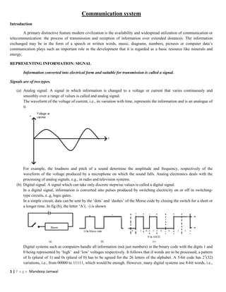
  • 1. 1 | P a g e Mandeep Jamwal Communication system Introduction A primary distinctive feature modern civilization is the availability and widespread utilization of communication or telecommunication: the process of transmission and reception of information over extended distances. The information exchanged may be in the form of a speech or written words, music, diagrams, numbers, pictures or computer data’s communication plays such an important role in the development that it is regarded as a basic resource like minerals and energy, REPRESENTING INFORMATION: SIGNAL Information converted into electrical form and suitable for transmission is called a signal. Signals are of two types. (a) Analog signal: A signal in which information is changed to a voltage or current that varies continuously and smoothly over a range of values is called and analog signal. The waveform of the voltage of current, i.e., its variation with time, represents the information and is an analogue of it. For example, the loudness and pitch of a sound determine the amplitude and frequency, respectively of the waveform of the voltage produced by a microphone on which the sound falls. Analog electronics deals with the processing of analog signals, e.g., in radio and television systems. (b) Digital signal: A signal which can take only discrete stepwise values is called a digital signal. In a digital signal, information is converted into pulses produced by switching electricity on or off in switching- type circuits, e..g, logic gates. In a simple circuit, data can be sent by the ‘dots’ and ‘dashes’ of the Morse code by closing the switch for a short or a longer time. In fig (b), the letter ‘A’(. -) is shown Digital systems such as computers handle all information (not just numbers) in the binary code with the digits 1 and 0 being represented by ‘high’ and ‘low’ voltages respectively. It follows that if words are to be processed, a pattern of Is (plural of 1) and 0s (plural of 0) has to be agreed for the 26 letters of the alphabet. A 5-bit code has 25 (32) variations, i.e., from 00000 to 11111, which would be enough. However, many digital systems use 8-bit words, i.e.,
  • 2. 2 | P a g e Mandeep Jamwal bytes. The American Standard at code for information Interchange (ASCII) is an 8-bit code that allows 28 (256) characters to be coded in binary. This is adequate for all letters of the alphabet (capital and small), the numbers 0 to 9, punctuation marks and other symbols fig (c), shows one 8-bit pulse, which represents the letter capital S in ASCII. Advantage of Digital Signals Information in digital form has certain important advantages over that in analog form in spite of the fact that many input devices (e.g., microphones, thermostats) produce analog signals. The following are the reasons for this. (i) Digital signals can be transmitted over long distance without error because of their ability to cope up with noise. (ii) Digital signals fit in with modern technology and can be used with both telecommunication and data processing equipment. (iii) Digital systems are easier to design and build (mostly from logic gates) and can be integrated on a single silicon chip. BASIC COMMUNICAITON TERMINOLOGY: TEMINOLOGY OF COMMUNICAITON Apart from the terms we have already used, the following additional ones of great help to understood the principle of communication. (i) Transducer: an electrical transducer is a device that converts some physical variable like pressure, displacement, force, temperature etc. into corresponding variations in the electrical signal at its output. (ii) Noise: Stray unwanted voltages and currents which disturb the transmission and processing of message signals constitute noise. The noise distorts the waveform and causes ‘hiss’ and ‘hum’ in loudspeakers. The source generating noise may be coated inside (the random motion of the carbon granules in a telephone mouthpiece) or outside the system (sparking of a car ignition system.) (iii) Transmitter: it process the incoming message signal and makes it suitable for transmission though a channel and subsequent reception. (iv) Receiver: It extracts the desired message signals from the received signals at the output of the channel. (v) Antenna: an antenna (or aerial) radiates or receives radio waves. Any conductor can act an antenna but proper design is necessary for maximum efficiency. The dipole antenna consists of two vertical or horizontal conducting rod or wires, Each of length ߣ/4, where ߣis the wavelength of the wave to be emitted and is centre fed. A dipole antenna is frequently used for frequencies below 30 MHz. Wheereas transmitting aerials may handle many kW of r f power, receiving aerials, though basically similar, deal with only a few mV due to voltages (of a few mV) an currents induced in the bypassing radio waves.
  • 3. 3 | P a g e Mandeep Jamwal (vi) Attenuation: The weakening of a signal as it propagates through a medium is called attenuation. (vii) Amplification: The process of increasing the amplitude and consequently the strength of a signal is called amplification and the electronic circuit that performs this task is called an amplifier. Amplification is necessary to compensate the loss in strength of the signal in communication. The energy required for this purpose is supplied by a dc power source. Amplification is done at a place between the source and the receptor of information wherever the signal becomes weaker than the required strength. (viii) Range: The largest distance between the source and the receptor of information (i.e., destination) upto which the signal has sufficient strength is called the range of the signal. (ix) Bandwidth: The range of frequencies a signal occupies or over which an equipment operates is called bandwidth. (x) Modulation: the process of mixing low frequency signal (called message signal) and a high frequency signal (called carrier signal) is called modulation. (xi) Demodulation or Detection: The process of recovering the message signal from the high frequency signal received by the receive is called demodulation or detection. (xii) Baseband Signals: Practically, no message signal is of single frequency. In fact, a message signal representing the original signal delivered by the source of information, consist of a band of frequencies. As such, these are called base band signals. (xiii) Repeater: In communication, range is of great importance. To extend the range, use is made of a repeater, which is a combination of a receiver and a transmitter. A repeater picks up the signal from the transmitter, amplifier it and then retransmits to the next receiver as shown in fig. A communication satellite is in fact a repeater station in geostationary orbit. (xiv) Distortion: The extent to which a system fails to reproduce accurately at its output the characteristics of the input is called distortion. We are presently concerned with electrical distortion in which the waveform of voltage of current is modified by a transmission system or network. It involves the introduction of features that do not appear in the original signal or the suppression or modification of features that are present in the original signal. ELEMENTS OF A COMMUNICAITON SYSTEM All communication system have three essential components: namely transmitter, receiver and channel.
  • 4. 4 | P a g e Mandeep Jamwal (i) Transmitter: It converts the message signal produced by the source of information into a form suitable for transmission and reception. A transmitter may have to be coupled with an electrical transducer in case the output of the information source is a non electrical signal, e.g., a voice signal. (ii) Channel: It is the link between the transmitter and the receiver. The channel ay be in the form of wires or cable s connecting the transmitter or the receiver for it may be wireless. As a transmitted signal propagates along the channel, it is weakened and gets distorted due to channel imperfection. It also packs up noise. (iii) Receiver: It receives the transmitted signal, extracts the original message signal from it and then delivers it to the receptor (i.e., user of information) after reconstruction (i.e, after eliminating noise and distortion). MODES OF COMMUNICAITON There are two basic modes of communication. (i) Point to point communication: It is the mode in which communication takes place via a link between a single transmitter and a receiver, e.g., telephonic conversation. (ii) Broadcast: It is the mode in which communication takes place via a link between a single transmitter and a large number of receivers, e.g., radio and television. BANWIDTH (BW) OF A SIGNAL The range of frequencies occupied by a signal is called the bandwidth of the signal. Different types of signals (voice, music, picture, computer date) have different bandwidths. The type of communication system needed for transmission and reception for a given signal depends upon its BW. (a) For intelligible speech signals, a frequency range of 300 Hz to 3100 Hz is considered adequate. Thus for transmission of a speech signal, a bandwidth of 2800 Hz (3100 Hz- 300 Hz) is required. Thus is o in the case of telephonic communication. (b) For high quality musical sound signals, where musical instruments produce high frequencies, a bandwidth of 20 kHz is required, for transmission of such signals (audible range extends from 20 Hz to 20 kHz) (c) For video singles, which transmit pictures, a bandwidth of 4.2 MHz is required for their transmission. (d) TV signals, which contain both audio (voice) and video (picture) signals, a bandwidth of 6 MHz is usually allotted for their transmission. Note: digital signals are in the form of rectangular waves. It can be shown that a rectangular wave is due to superimposition of sinusoidal waves of frequencies v0, 2v0, 3v0 …. ∞ (where v0 is the fundamental frequency), which implies an infinite bandwidth. BANDWIDTH OF A TRANSMITTING MEDIUM The range of frequencies offered by a transmitting medium is called the bandwidth of the transmitting medium.
  • 5. 5 | P a g e Mandeep Jamwal The bandwidths of some of the commonly used transmitting media are given below: (i) Coaxial cable : = 750 MHz (ii) Free space : = a few kHz to a few GHz (iii) Optical fibre : In excess of 100 GHz. PROPAGATION OF RADIO WAVES Radio waves are a member of the electromagnetic family of waves. They are energy carriers which travel at eh peed of light, their frequency v and wavelength ߣbeign related by te equation c = v ߣ. If ߣ = 300 m.v = ௖ ఒ = ଷ.଴ ௑ ଵ଴ఴ ௠ /௦ ଷ଴଴௠ = 106 Hz = 1 MHz The smaller the ߣ, the arger the v. Radio wave can be described either by their frequency or their wavelength, but the former is more fundamental sice unlike ߣ(and v). v does not change when the wave travels from one medium to another. They have frequencies extending from 30 kHz upwards and are grouped into band along with their uses in Table. Frequency band Some uses 1. Low frequency (LF) (30 kHz – 300 kHz) 2. Medium frequency (MF) (300 kHz – 3 MHz) 3. High frequency (HF) (3 MHz – 30 MHz) 4. Very high frequency (VHF) (30 MHz – 300 MHz) 5. Ultra high frequency (UHF) (300 MHz – 3 GHz) 6. Microwave frequency (Above 3 GHz) Long wave radio and communication over large distance Medium wave, local and distant radio Short wave radio and communication , amateur and CB radio TV, F radio, police, meteorology devices TV (bands 4 and 5), aircraft lading systems Radar, communication satellites, mobile telephones and TV links Radio wave can travel from the transiting to recovering antenna in one or more of three different ways depending upon their frequency. These modes of wave propagation have been discussed in subsequent articles. GROUND WAVE: SURFACE WAVE In ground wave propagation, the radio waves are guided by the Earth and travel along its curved surface from the transmitter to the receiver. Ground wave propagation has been shown in fig.
  • 6. 6 | P a g e Mandeep Jamwal Some important characteristic of ground waves are as follows. (i) Ground waves are greatly affected by the electrical properties of the ground over which they move. Poor conductors such as and absorb more energy from these waves than water. (ii) The range of coverage depends on the transmitted power and frequency. (iii) Ground wave propagation is useful only at low frequency since high frequency waves are greatly absorbed by the ground. (iv) The range of these waves is about 1500 km at low frequencies (long waves). AM radio broadcast in the medium frequency band (meant for local areas) is carried out mainly by ground wave. (v) The range of these waves is much less for VHF due to their increased absorption at higher frequency. (vi) Ground wave transmission has the merit of being extremely reliable, irrespective of atmospheric condition. SKY WAVE: IONOSPHERIC WAVE In sky wave propagation, the radio wave travels skywards and if its frequency is below certain critical frequency (typically 30 MHz) , it is returned to the Earth by the ionosphere. The sky wave below critical frequency travels from the transiting antenna (T) to the receiving antenna (A) via ionosphere. The ionosphere consist of layers of air molecules (the D, E , F1, F2 layers), stretching from about 65 km to 400 km, which have become positively charged through the removal of electrons by the Sun’s ultraviolet radiation. On striking the earth, the sky wave bunches back to the ionosphere where it is again gradually refracted and returned earthwards as if by ‘ reflection’ . this continues until it is completely attenuated. The critical frequency varies with the time of day and seasons. Following are the important features of sky waves. (i) Sky wave of low, medium and high frequencies (LF, MF, HF) i.e., below 30 MHz can travel thousand of km. (ii) Sky waves of very high frequency (VHF), an above, i.e., above 30 MHz, usually pass through the ionosphere into outer space. (iii) Short wave (3MHz, to 30 MHz) transmission around the globe takes place by sky waves via successive reflections at the Earth’s surface and the ionosphere.
  • 7. 7 | P a g e Mandeep Jamwal (iv) Sky wave transmission is an elusive and tricky business as it is subject to fading and disappearing of signals. This is due to erratic changes in the ionosphere with seasons, night and day and atmospheric condition. But in spite of its, if it is the primary means of around-the world short wave communication. SPACE WAVE In space wave propagation , the radio wave travels in a straight line from transmitting antenna to the receiving antenna. Some of the salient features of the space wave are as follows. (i) Since a space wave travels within the first 15 km over the surface of the Earth, i.e., in the Earth’s troposphere, their propagation is also called tropospherical propagation. (ii) A space wave is usually made up of two components: (a) The direct or line- of-sight wave fro the transmitting to the receiving antenna (b) The ground reflected wave travelling from the transmitting antenna to the Earth and reflected to the receiving antenna. (iii) For VHF, UHF and microwave signals, only the space wave, giving the line-of sight (LOS) propagation, is effective. (iv) As the space wave does not undergo continuous absorption by the Earth’s surface, it can cover greater distance than the ground wave. (v) A range of upto 150 km is possible on Earth if the transmitting aerials are on high ground and there are no intervening obstacles such as hills, buildings or trees. (vi) Space waves are used for satellite communications, television broadcast and microwave links. (vii) In general, space wave propagation is affected by weather conditions in the lower atmosphere and the subject to changes with variation in temperature, humidity an air pressure. RANGE OF A TRANSMITTING ANTENNA: RADIO HORZON In fig, AP is the height (hT) of the transmitting tower, if the transmitting antenna is at A, then signals transmitted by it cannot reach beyond the places B and C on Earth, which are obtained by drawing tangents from A to the Earth’s surface.
  • 8. 8 | P a g e Mandeep Jamwal Clearly, PB = PC = dr(radio horizon of the transmitter) In ΔACO, AC2 + OC2 = AO2 Or ்݀ ଶ + R2 = (R + hT)2 (as AC = PC = DT) Or ்݀ ଶ + R2 + R2 + ℎ் ଶ = 2 RhT (1 + ௛೅ ଶோ Since hT << R, (hT/2R) can be neglected Clearly, ்݀ ଶ = 2RhT Or dT = ඥ2ܴℎ் …(1) RANGE OF APCE WAVE PROPAGATION ON EARTH’S SURFACE In fig, hT and hR represent the heights of the transiting and receiving antennas.
  • 9. 9 | P a g e Mandeep Jamwal When the space wave takes from the transmitting to receiving antennas without being obstructed by the curvature of the Earth, the line of sight between the two antennas touches the horizon(H). If dT and dR are the distances( called the radio horizons) of the transmitting and receiving antennas from H, then DT = ඥ2ܴℎ் and dR = ඥ2ܴℎோ Clearly, maximum line of sight distance between the two antennas, i.e., DM = dT + dR = ඥ2ܴℎ் + ඥ2ܴℎோ …(1) Obviously, dM is the range of space wave propagating between the two antennas on the Earth. MODULATION The process of superimposing the low frequency message signal on a high frequency wave (called the carrier wave) is called modulation. The low frequency message signal is called modulating signal or modulating wave and the resultant of modulating wave and carrier wave is called modulated carrier wave or the modulated signal. Need for Modulation Although audio frequency signals may be transmitted directly by cable, in general, and certainly in radio and TV, a carrier wave is required as is clear from the following arguments. (a) Size of the antenna: for transmitting a signal, we need an antenna (also called an aerial) which should have a size comparable to the wavelength (ߣ) (or at least ~ ߣ/4) of th signal. For eample, in case of a signal (an e.m. wave travelling with speed c = 3 X 10⁵ k/s) of frequency 20 kHz, ߣ = ௖ ௩ = ଷ௑ ଵ଴ఱ ௞௠ / ௦ ଶ଴ ௑ ଵ଴య / ௦ = 15 km Obviously, this is an impossible size for an antenna. Hence, the necessity of carrier wave (of high frequency) to reduce the size of the antenna to transmit the signal. (b) Effective power radiated by an antenna: it can be shown that the power (P) emitted by a linear antenna of length I while radiating e m waves of wavelength ߣis given by P ∝ ( ଵ ఒ )2 For a baseband signal of low frequency, wavelength (ߣ) is large and as such P is also small. Obviously, such a signal will to be able to travel long distances. Hence, the need for high frequency waves (carrier waves) to increase P to carry the baseband signal over long distances. (c) Mixing up of baseband signals from different transmitters: When different transmitters are transmitting signals will get mixed up and we will not be able to distinguish between them. To overcome this difficulty, a unique carrier frequency is allotted to each signal for its transmission. Thus, modulation makes it possible to use discrete non interfering frequency channels for carrying on a number of simultaneous transmissions in a locality. TYPES OF MUDULATION A carrier wave may be sinusoidal (continuous) or in the form of a pulse. Both types of wave can be modulated. A sinusoidal carrier wave can be represented as: c(t)= Ac sin (߱c t + φ)
  • 10. 10 | P a g e Mandeep Jamwal Where c(t) = strength (voltage or current) of carrier waves at time t Ac = amplitude of the carrier wave ߱c ( = 2ߨvc) = angular frequency of the carrier wave φ = initial phase of the carrier in modulation, any of these three parameters (Ac , ߱c and φ) of the carrier is changed by the modulating signal (i.e., information or message signal). Accordingly, modulation of the sinusoidal carrier wave can be carried out in the following three ways. (a) Amplitude Modulation (AM): In amplitude modulation, the amplitude of the carrier is varied by the modulating signal and the change in amplitude form the unmodulated value is directly proportional to the instantaneous value of the modulating signal it is independent of its frequency. This is represented in fig. (b) Frequency Modulation (FM): In frequency modulation, the instantaneous frequency of the carrier is varied by the modulating signal. The instantaneous deviation of frequency from then modulated value is directly proportional to the instantaneous value of the modulating signal but is independent of its frequency. This is represented in fig. (c) Phase modulation: in phase modulation, the instantaneous phase angle of the carrier is varied by the modulating signal. The instantaneous deviation of the phase angle from the unmodulatd value is directly proportional to he instantaneous value of the modulating signal but is independent of its frequency. AMPLITUDE MODULATION (AM) In amplitude modulation, the information signal (modulating signal) is used to vary the amplitude of the carrier so that it follows the wave shape of the information signal. Let the carrier wave (assume sinusoidal) be represented by C(t) = Ac sin ߱ct …(1)
  • 11. 11 | P a g e Mandeep Jamwal Further, for simplicity, let us suppose that the modulating signal is also sinusoidal and is represent by M(t) =Am sin ߱mt …(2) Where ߱m is the angular frequency of the modulating signal. In practice ߱m is small compared to ߱c. In radio transmission, ߱m/ ߱c = 1/1000, The amplitude modulated (AM) carrier signal is given by Cm (t) = (Ac + Am sin ߱m t) sin ߱ct or cm(t) = Ac (1 + µ sin ߱mt) sin ߱ct …(3) where µ = ஺೘ ஺೎ …(4) here, µ is called modulation index, modulation factor or depth of modulation. In practice to avoid distortion, µ< 1. Modulation Index in term of Amplitude of AM Carrier Wave From eqn. (3), amplitude of AM carrier wave, M = Ac (1 +µ sin ߱mt) …(5) Maximum value of M (when sin ߱m t = +1) i.e., M1 = Ac (1 + µ) … (6) Minimum value of M (when sin ߱m t = -1), i.e., M2 = Ac (1 - µ) …(7) Thus, M1 + M2 = 2Ac And M1 – M2 = 2µ Ac …(8) Clearly, µ= ெ భ ି ெమ ெ భ ି ெ మ …(9) From eqn. (3). Cm(t) = Ac sin ߱c t + µAc sin ߱c t sin ߱m t = Ac sin ߱c t + µ஺೎ ଶ cos (߱c - ߱m) t - µ஺೎ ଶ cos (߱c + ߱m) t …(10) (as sin A sin B = ଵ ଶ [{cos (A – B) – cos (A + B)}]) Frequency Spectrum of AM Carrier Wave From eqn. (10), it is clear that AM carrier wave, with sinusoidal modulation, consists of three components. (i) Original carrier wave of amplitude Ac and frequency vc = ߱c /2ߨ.
  • 12. 12 | P a g e Mandeep Jamwal (ii) A wave of amplitude µAc/2 and frequency (vc – vm) = (߱ = ߱m) /2ߨ. This frequency I called the Lower Side Frequency (LSF). (iii) A wave of amplitude of µAc/2 but of frequency (vc + vm) = (߱c + ߱m) /2ߨ. This frequency is called the Uper Side Frequency (USF). Fig (a) or (b), which gives the amplitudes of these frequency components is known as the frequency spectrum. It is clear that information (i.e., modulating signal) is contained in side frequency components and not the carrier component. The difference between USF and LSF [i.e., (vc + v) – (vc – vm) is called the bandwidth and is equal to 2vm. Thus. In case of modulation by a single frequency, the BW is twice the modulation frequency. PRODUCTION AN TRANSISSION OF AM WAVE Production of AM Wave There are variety of method s to produce an AM wave. A block diagram of a simple modulator for obtaining AM wave, using a square-law device, is shown in fig Let the modulating signal and the carrier be represented by
  • 13. 13 | P a g e Mandeep Jamwal M(t) = Am sin ߱mt …(1) And c(t) = Ac sin ߱ct …(2) If x(t) is the resultant signal obtained by adding m(t) and c(t), then X(t) = m (t) + c(t) = Am sin ߱m t + Ac sin ߱c t …(3) Let x(t) be passed through the square law dive which produces an output y(t) according to the relation Y(t) = B[x (t)] + C [x(t)]2 …(4) Where B and C are constants. Thus, from eqns. (3) and (4), Y(t) = B [Am sin ߱m t + Ac sin ߱c t] + C [‫ܣ‬௠ ଶ sin2 ߱mt + ‫ܣ‬௖ ଶ sin2 ߱c t + 2AmAc sin ߱m t sin ߱c t] = BAm sin ߱m t + BAc sin ߱c t + ஼ ଶ (‫ܣ‬௠ ଶ + ‫ܣ‬௖ ଶ ) – ஼஺೘ మ ଶ cos2 ߱mt - ஼஺಴ మ ଶ cos2 ߱mt + CAmAc cos (߱c - ߱m) t – CAmAc cos (߱c + ߱m) t …(5) [as sin2 A = (1 - cos2 A) and 2 sin A sin B = cos(A – B) – cos (A+B)] It is obvious from eqn.(5) that output y (t) consists of: (a) One dc component: ஼ ଶ (‫ܣ‬௠ ଶ + ‫ܣ‬௖ ଶ ) (b) Six ac components of frequencies: ߱m, 2߱m, ߱c, 2߱c, (߱c - ߱m) and (߱c + ߱m) When the output [y(t) is passed through band pass filter, centered at ߱c, it rejects dc component (of zero frequency) and the ac components of frequencies ߱m, 2߱m(which are much lower than ߱c) and 2߱c (which is double than ߱c) and allows only ߱c, (߱c - ߱m) and (߱c + ߱m). Thus, the output of the band pass filter is given by Y’(t) = BAc sin ߱c t +CAm Ac cos (߱c - ߱m) t - CAmAc cos (߱c + ߱m) t …(6) Clearly, y’ (t) has the same form as that of an AM wave obtained by superimposing a modulating signal of frequency ߱m on a carrier of frequency ߱c. Transmission of AM wave The AM signal generated by the modulator cannot be transmitted as such as it has to be provided necessary power to cover the desired range. This is done by feeding the AM signal to a power amplifier as shown in fig
  • 14. 14 | P a g e Mandeep Jamwal The amplified AM signal is fed to an antenna of appropriate size for onward transmission. DETECTION OF AM WAVE The process of recovering the modulating signal (i.e., information) from the modulated carrier wave is called detection and the circuit that performs this function is called a detector. The complete circuit which receives the modulated carrier, detects the modulating signal and then amplifier it, is called a receiver. For amplitude and frequency modulated signals, AM and FM receivers are used . For the sake of simplicity, the basic features of an AM receiver are shown in fig. Radio frequency (RF) amplifier: The AM wave gets weakened as it propagates through the channel from eh transmitting antenna to the receiving antenna. To amplify this wave, an RF amplifier is connected to the receiving antenna.
  • 15. 15 | P a g e Mandeep Jamwal (i) Intermediate Frequency (IF) stage: Before detection, the carrier frequency (߱c) of the AM wave is changed to a lower frequency (߱c) and amplification is carried out at this frequency. This process is carried out with the help of an IF stage consisting of a local oscillator, a mixer and an IF amplifier. (ii) Detector: Its purpose is to detect the envelope of the AM wave because this envelope is the modulating signal containing the information. (iii) Audio frequency (AF) amplifier: This amplifier is coupled to the output of ht detector and amplifier the detected modulating signal which appears at its output. DETECTOR FOR AM WAVES We hall describe the function f a detector in some detail with the help of the a block of a detector in some detail with the help of a block diagram of a detector of AM signal. The IF signal received by the detector contains the angular frequencies ߱c’, (߱c’ - ߱m) and (߱c’ + ߱m). in order to separate ߱m, i.e., to obtain modulating signal, a simple AM signal detector is shown in fig. (i) The AM wave from the IF stage is passed through a rectifier(pn junction diode) which produces a rectified wave as shown in fig (b). (ii) The enlope of this rectified wave has a frequency ߱m and is the message signal m(t) as shown in fig (b). (iii) The rectified signal is passed through an envelope detector (RC parallel network), to retrieve m(t as shown in fig (C). INTERNET The global network of computers is called internet or simply net. Internet is, in fact, the short form in INTER-NET work which is the interconnected network of all the world wide main computer (called severs*). (a) Networking of Computers: When two or more computers share information through connecting wires or by some wireless means of communication like Wi-Fi**, they are said to be networked. (i) Local Area Network(LAN): It is a network of computers on a small scale, e.g., within an
  • 16. 16 | P a g e Mandeep Jamwal educational institution or an office. This network usually has other device like a printer, a scanner etc. connected to fig (a). (ii) Wide area network (WAN): It is assemble by connecting various LANs as shown in fig (b) (iii) Internet: to build internet, we connect various WANs fig (C). The first network of computer.
  • 17. 17 | P a g e Mandeep Jamwal Advanced research projects agency NETwork (ARPANET) was developed by the US in 1969. In India, internet was started in November 1998 by VSNL, (Videsh Sanchar Nigam Limited) in Mumbai. (b) Protocol: A system of digital rules for data exchange within or between computers is called communications protocol. A standard set of protocols. (TCP) or internet Protocol (IP) are used for the exchange of information through the internet. (c) Information on Internet: Information on Internet is provided /available through: (i) Webpage: It may contain text, images, videos etc. as a document, commonly written in HyperText Markup Language (HTML) that is accessible through the Interne. The first webpage was created at CERN by Turn Berners-Lee and put online August 6, 1991. (ii) Website: It is a central location that contains more than one webpage. In fact, it is a set of related WebPages typically served from a single web domain. Some web sites require a subscription to access some or all of their contents. (iii) World Wide Web (WWW or W3): All publically accessible Websites constitute the World Wide Web (commonly known as Web). (d) Applications of Internet: Internet has changed the way most of the world communicates. Out of the endless applications of internet, we briefly mention the following few: (i) Internet Surfing: it is an interesting way of searching and viewing information on any topic of interest by moving on internet from one webpage (or website) to another. (ii) Electronic mail (email or –e-mail): It is the most used application of Internet and is the cheapest and the fastest way of sending text written on computers, along with images and videos. For sending an email, a personal email account with an email-ID or email-address has to be created. An email –ID is protected with a password and has two parts separated y a sign @ (called at the rate of). For example, the email- ID of the author of this book surinderalal@gmail.com, provides personal information about the author(his name : SURINDRA LAL) and gail.com provides information about the server providing him the email facility. A message stored in an email account can viewed later even when the user is not connected to the internet. (iii) Electronic banking (e-banking, online banking, virtual banking): it is an electronic payment system that enables customers to conductor financial transactions on a website operated by the institution. For this
  • 18. 18 | P a g e Mandeep Jamwal facility a customer with internet access would need to register with the intuition of the eservice and set up some password for customer verification. (iv) Electronic shopping (E shopping, e commerce, online shopping): It is a form of electronic commerce which allows consumers to directly buy goods or services from a seller over the internet using web browser. The largest of these online retailing corporations are: alibaba, Amazon.com and ebay. (v) Electronic booking (E-booking, e ticketing): It is an application developed for booking railway tickets, flight tickets, hotel etc, through the internet. (vi) Social networking service(social networking site or SNS): It is a platform to build social networks or social relations among people who share interests, activities , backgrounds or real life connections. A social network service consists of a representation of each user(often a profile), his or her social links and a variety of additional services. It allows the users to share their ideas, pictures, events, activities etc. With their group. The most popular SNS are Facebook, Twitter, Linkedin, Google+, Instagram, Tagged etc. MOBIEL TELEPHONY Mobile technology which was conceptualized in 1970, took just a decase to be finally implemented. (a) Mobile Phone: it is a phone that can make and receive calls over a radio link while moving around a wide geographical area. It is, in fact, a handy computer that can be equipped with Internet. A mobile phone is also called a cellular phone, cell phone or simply a phone or a cell. The first hand hold cell was demonstrated by Motorola in 1973. Whereas in a walkie-talkie, the radio frequency is used of both sending and receiving signals, in a mobile, the outgoing and incoming signals use different frequencies and as such, the two individuals can talk and listen at he same time. (b) Working Principle of a Mobile phone (i) The central concept of mobile telephony is to divide the service area into suitable number of cells or cell zones. To completely cover a given are, use of hexagonal cells is the best possible way. All the Cells are centered on Mobile telephone switching Office (MTSO) which is basically is telephone exchange mobile phone calls. Each cell is provided with a low power transmitter, called base stations, which
  • 19. 19 | P a g e Mandeep Jamwal provides service to a large number of mobile users as each cell antenna ahs a working range of minimum 1.5 to 2 km and maximum upto 48 to 56 km or more m are around it. (ii) When a mobile user is out of the coverage area of one base station, it gets lined up with another base station through a process called hand over or hand off. This process is so quick that the mobile user does not even notice it. (c) Scientific process of Mobile phone Call (i) When a mobile number a dialed, an oscillator inside the mobile generates an e.m. wave of a particular frequency. This information carry e.m. wave is transmitted though the mobile antenna to the antenna of the cell. (ii) The cell antenna, in turn, transfers this signal (e.m. wave) to MTSO through the cellular radio network. (iii) The MTSO computer system identifiers the location (cell) of the mobile phone that has been dialed an connects it to that. (iv) The caller mobile on receiving the signal generates through an oscillator the dialer ID and displays it. The entire process is completed in a few seconds as all the signals are carried by e.m. wave which travel with the speed of light. (v) The mobile phone network is also called terrestrial cellular network a mobile phone call is transferred from dialer cell antenna to MTSO an from MTSO to caller cell antenna only through cell antennae lying in between. The process of a mobile phone call from dialer to the called is shown in fig (a) (d) Mobile phone numbering system To identify every mobile phone, a SIM (Subscriber Identity Module)car is inserted in it A SIM is a small IC integrated circuit) chip with a unique number. All SIM cards are issued by mobile operator companies and their information is provided to the MTSO. Every mobile number in India consists of 10 digits and has the prefix 9,8 or 7as per the National numbering plan 2003, a mobile number is split as XXXX- NNNNNN, where XXXX are Network Operator Digits and NNNNNN are the Subscriber Number Digits. Telecom Regulatory Authority of India, (TRAI) established in 1997 by an act of parliament, regulates the use of mobile phones in the country. (c) Mobile Network Generation With the technology advancing at the rapid rate and the increasing use of mobile phone it becomes essential to make the mobile phone networks more efficient. To mention the efficiency of these networks, use is made of the word ‘ Generation’ which is abbreviated as G. whereas 1G were the first generation networks and were base on analogue radio signals, 2 G were narrow band digital signal base networks. 3G networks increase the data transfer speed and 4 G are going to provide a high speed internet facility. It is interesting to go through the comparison between 1G, 2G, 3G and 4G. 1G 2G 3G 4G 2.4 kbps 64 kbps 2000kbps 100,000 kbps
  • 20. 20 | P a g e Mandeep Jamwal Grasshopper Dog 5storey building Burj Khalifa South Korea recently announced a $1.5 billion investment in 5G infrastructure upgrades and intends to rollout a limited trial network by 2017, with full availability by 2020. The 2 G network focused on voice, 3G on data and 4G on video. The new 5G network will be all abut connection, 7 trillion connect device in the coming decease and each individual will have at least ten connections. GLOBAL POSITIONING SYSTEM(GPS) GPS developed by the US defense department, uses between 24 to 32 medium earth orbit satellites and transmits signal on microwave frequencies. This enables the GPS to determine their current location, time an velocity. It is often used by civilian as navigation system. Cell phone incorporate GPS to help their users find their way and unknown places. Theoretically, a GPS receiver would be able to tell you positive down to the width of your finger. India’s first navigational satellite [INSS] was successfully placed in orbit by PSI V -2 on July,2013. (a) Working principle To use GPS system of satellite, a GPS device fitted with a transmitter /receiver for sending / receiving signals is needed to link up with GPS satellite. The unique location of a GPS user is determine by measuring its distance from at least three GPS satellites. To measure these distance, the time (t) taken by a radio signal to travel from the device to a satellite and back is recorded by the device (using the relation, D = ct). let D1 D2 and D3 be the distances of three satellites form the GPS device. (i) If the user is at a distance D1= from satellite-1, then its location can be anywhere on the circumference of circle of the radius D1 (ii) If the user is at a distance D2 form the satellite -2 then its location can be either at X or Y, the points where the circumference of circles of radii D1 and D2 interest. (iii) if the user is at a distance D3 from the satellite-3 then this location will be at the points of intersection of circumferences of circles of radii D1 , D2 and D3 form the satellites- 1, 2 and 3 respectively. as is clear from fig, the user is at the point Y. Obviously, Y gives the exact location (longitude coordinates) of the GPS device users on the display board. (iv) If a person is at some height above the earth’s surface then using the distance information from 4 GPS satellites, even altitude of the user can also be measured. Note: since all the 24-GPS satellites are in predefine orbits, their locations are precisely determined. Obviously, it is these known locations of 3 or 4-GPS satellites and their distance to GPS device that enable the GPS user . its computing device) in locating its longitude coordinates.
  • 21. 21 | P a g e Mandeep Jamwal (b) Applications of GPs A GOS system helps in (i) Navigation on land, water and air’ (ii) Map designing of a location (iii) Automatic vehicle movements (iv) Measuring speed of moving objects (v) Locating change in position of glaciers and mountain heights (vi) Keeping standard time all over the world (vii) Tracking animals and birds and studying their movements by attaching SPS device to their bodies (viii) Airplane traffic movement (ix) Visually impaired persons in location identification