Continuous miners
•Transferir como PPTX, PDF•
16 gostaram•7,451 visualizações

The document discusses continuous miners used in underground mining. It describes the JOY continuous miner product line which includes three machine classes for different mining heights: 14CM, 12CM, and 12HM series. Key components of the continuous miners are described, including the cutter, gathering head, conveyor, traction, dust collector, hydraulics, and electrical systems. Specifications for the Joy 12CM15 continuous miner used in two mining projects are also provided.

Recomendados
Mais conteúdo relacionado
Mais procurados
Mais procurados (20)
Semelhante a Continuous miners
Semelhante a Continuous miners (20)
Último
Último (20)
Continuous miners
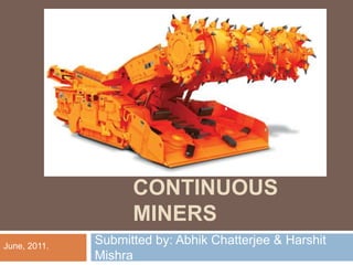
- 1. CONTINUOUS MINERS Submitted by: Abhik Chatterjee & Harshit Mishra June, 2011.
- 2. Another view of the monster : -
- 3. INTRODUCTION : The JOY continuous miner product line has been developed to meet the high productivity requirements of today's underground mining industry. Each machine employs Joy’s multi-motor concept with outboard access to motors, gearcases, controllers and other major components.
- 4. Types available in the market : - The continuous miner product range is segmented by mining height requirements into three machine classes for low, medium and high-seam applications. 14CM Series Continuous Miners 12CM Series Continuous Miners 12HM Series Continuous Miners
- 5. 14CM Series Continuous Miners Application Specific Cutting Systems Optimum Fluid Control Proven Conveyor System Wethead Cutterhead Systems
- 6. 12CM Series Continuous Miners High Voltage Capability Maintainability and Serviceability Wethead Cutterhead Systems Dual-Sprocket Chain Conveyor System
- 7. 12HM Series Continuous Miners Largest manufactured by Joy Heavy-duty crawler chain, along with a heavy- duty drive system Can incorporate an onboard closed loop cooling system. 38 inch (965 mm) conveyor for increased production capability.
- 8. The Continuous Miners used in the Sarpi and Jajhra projects of Joy are of the 12CM Series. There are two CMs one in each of the projects. Focus : -
- 9. Main parts of a Continuous Miner : - Cutter Gathering head Conveyor Traction Dust collector Manifold Hydraulics Electrical Circuits
- 10. Specification : - Joy 12CM15 is a high capacity, totally remote controlled CM designed for medium to high coal seam applications. The machine has Cutter head drum Diameter - 1.12m Cutting Width - 3.3m Max cutting height - 4.6m Conveyor width - 0.76m with 2.41m/s speed
- 11. Specification : - CM is equipped with 2 cutter heads, with standard clutch protected, AC induction Motors (170kw) mounted parallel to centreline of boom frame. Each cutter motor connects to the gearing of gear case using an internal torque shafts. 2 gathering head motors (AC) of 40kw 2 traction motors (DC) of 26kw 1 pump motor of 52kw; 1 dust collector fan motor 19kw. Total Weight of CM = 58 tonns(58376kg)
- 12. Cutter : - Left Cutter Drum Centre Cutter Drum Right Cutter
- 13. There are 2 cutter motor one in each side of the machine. AC induction, 1500 rpm 170kw each. Cutter Motor.
- 14. Tungsten carbide teeth used for cutting. Replaced when broken and treated as consumables. Teeth.
- 15. 5 Ton Hydraulic Jack. Cutter boom. Cutter Boom Shear Cylinders
- 16. Gathering head : - Centrifugal Loading Arm
- 17. Consists of Gathering head motors(2) which run CLA’s(centrifugal loading arms) which are responsible for loading coal in to conveyor. These CLA’s rotate in opposite direction to each other. Gathering head motor (AC induction) – 2 in no’s, each of 40kw. GATHERING HEAD & CONVEYOR
- 18. 2 gathering head motors drive centrifugal loading arms, which are responsible for gathering the cut coal and convey it to conveyor. The conveyor, having conveyor chain is responsible for the movement of coal from foot shaft to the end of conveyor, which dumps into Shuttle car. GATHERING HEAD & CONVEYOR
- 19. There are 2 Gathering motor one in each side of the machine. AC induction 40kw each. Gathering Motor.
- 20. Above fig is the spline groove where the torque shaft sits. Torque Shaft Torque shafts of cutter motors and Gathering head motors.
- 21. Conveyor : - Foot Shaft Flight
- 22. Foot shaft is a shaft with a (4 toothed) sprocket, over which the flight bar chain sits, whose construction is responsible for movement of coal. Rear Conveyor.
- 23. The movement of flight bar is >100mm from center ----chain should be tightened. The movement of flight bar is <50mm from center ----chain should be loosened. Conveyor Chain Adjustment:
- 24. A loose chain may jam, a tight chain may become overloaded causing high temperature in the drive or foot shaft leading to excessive wear. So, in order to address this issue a tension adjustment arrangement is made by incorporating a spring at the end of the take up cylinder to the side of swing conveyor. Conveyor Chain Adjustment:
- 26. Gathering head is raised and lowered by a single acting lift cylinder on each side of the machine. (pic above) Gathering Head Lift Cylinder.
- 27. Traction : -
- 28. Incorporates Crawler chain, brakes, Traction Motor, Traction planetary and Traction Reducer. Traction motors are of 26kw of DC. Traction motors are connected with reducer and the sun and planetary arrangement helps the crawler chain to move which sits on the sprocket connected with sun shaft. Traction :
- 29. Traction Motor.
- 30. Traction Planetary, to which sun shaft is connected. Sun and Planetary arrangement.
- 31. Traction : - It is equipped with spring applied, hydraulically- released traction brakes, which are normally applied. Springs inside brake assembly push a piston against brake disks results in stoppage. These are released when hydraulic pressure is applied to compress the springs and retract the piston. The brake has a wear indicator pin that should protrude approximately 2-2.8mm from the face of brake.
- 32. When machine is stationary, the solenoid is in its normal, closed position, blocking hydraulic flow to the brakes. When brakes are released a signal sent from the control system to traction brake solenoid when ever its trams. Spring used in traction.
- 33. This uses a slurry pump – motor to remove slurry from dust collector sump. It is located in the dust collector fan compartment. Dust Collector.
- 34. Manifold Hydraulics : - Test Unit for measuring.... Flow Pressure Temp.. Power Fill Used for oil filling
- 35. Manifold Hydraulics : - Pump Circuit. Stabilizer Circuit. Conveyor Elevate Circuit. Conveyor Swing Circuit. Gathering Head Circuit. Shear Circuit. Power Take-Off Circuit. Water System. Traction Brake Circuit.
- 36. Gathering manifold gate: The gathering head circuit includes components which permit pressure assist against the gathering head. Components include sequence cartridge, a check cartridge and a bleed off valve. In addition to it an accumulator is also connected to the manifold, permits to place the head in float position. Accumulator receives or supplies fluid to gathering head cylinders as they retract or extend during float function.
- 38. Mounted under the rear of the machine allows the operator to raise or lower the back of the machine. Consists of a single cylinder mounted (or stab shoe) to the under side of the rear frame When this is completely extended, the stab shoe will be supporting part of the weight of the machine. Extending the stabilizer cylinder lifts the rear of the machine. Stabilizer cylinder
- 39. Conveyor Elevate circuit: These cylinders position the end of the conveyor at the proper height for loading operations. The conveyor is hinged to the machine frame and two single –acting, telescopic hydraulic cylinders raise it. The second rating is a high pressure relief setting to protect the hydraulic cylinders from large pressure caused by roof falls. Conveyor elevate port relief protects the circuit from over pressure and set between 120.6-
- 40. The conveyor swing cylinder allows the machine operator to swing the rear of the conveyor from side to side as needed to assist loading. Port relief settings for extend and retract port relief valves protect the circuit from over pressure. They are 89.6-96.5 bars. Conveyor Swing circuit:
- 41. Electrical Circuits : - Pilot Control. Breaker Circuit. Control and Lighting Circuit. Pump Circuit. Cutter Circuit. Dust Collector Circuit. Conveyor Head circuit. Gathering Head Circuit. Traction Head Circuit.
- 42. Circuit Breakers: BREAKER Function Main Breaker Provides power to all other breakers Cutter & Gathering Head/Conveyor breaker Provides power to cutter & gathering head/conveyor motors circuits Traction Breaker Provides power to traction motor circuit Lights breaker Provides lights to lighting circuits.
- 43. Electrical System: The input power to the CM is a 3 phase 950v ac (though 1100v or 1.1KV is the specified value). Traction motors are controlled with a dual 6SCR drive system. A control Transformer drops the line voltage to 110v AC for the control circuit, and 12 volts for the head light circuit. As the resistance to the drums at cutter motor is increased, the current monitoring feature will regulate the DC input voltage to tram motors, and regulate the available tram speed to the machine.
- 44. Electrical System: Traction Motor voltages: Input to traction determines the SCR power output or motor voltage of the SCR firing package. With cutters off, SLOW – 90v dc MEDIUM – 180v dc FAST- 365v dc Current limit may reduce output voltage in any speed if traction current is too high.
- 45. Electrical System: Traction Current limit is set at maximum 360A dc and is non- adjustable. Traction current is monitored by current transformers. Machine is designed to provide 270v ac 3 phase (A, B, C) to the power section @ 100% machine voltage. Phase is not critical as long as both the drive (left and right) are in same phase.