SlideShare uma empresa Scribd logo
1 de 67
Metal casting processes
• Casting is one of the oldest manufacturing process. It is the first step in
making most of the products.
• Steps: - Making mould cavity - Material is first liquefied by properly
heating it in a suitable furnace. - Liquid is poured into a prepared mould
cavity - allowed to solidify - product is taken out of the mould cavity,
trimmed and made to shape
We should concentrate on the following for successful casting operation:
• Preparation of moulds of patterns
• Melting and pouring of the liquefied metal
• Solidification and further cooling to room temperature
• Defects and inspection
Advantages
• Molten material can flow into very small sections so that intricate shapes
can be made by this process. As a result, many other operations, such as
machining, forging, and welding, can be minimized.
• Possible to cast practically any material: ferrous or non-ferrous.
• The necessary tools required for casting moulds are very simple and
inexpensive. As a result, for production of a small lot, it is the ideal
process.
• There are certain parts (like turbine blades) made from metals and alloys
that can only be processed this way. Turbine blades: Fully casting + last
machining.
• Size and weight of the product is not a limitation for the casting process.
Limitations
• Dimensional accuracy and surface finish of the castings made by sand
casting processes are a limitation to this technique.
• Many new casting processes have been developed which can take into
consideration the aspects of dimensional accuracy and surface finish.
Some of these processes are die casting process, investment casting
process, vacuum-sealed moulding process, and shell moulding process.
• Metal casting is a labour intensive process
Pattern
• A Pattern is a model or the replica of the object to be cast.
• Except for the various allowances a pattern exactly resembles the casting
to bemade.
• Patterns may be in two or three pieces, where as casting are in a single
piece.
• A pattern is required even if one object has to be cast.
• The quality of casting and the final product will be effected to a great
extent by theplanning of pattern.
• A Pattern prepares a mould cavity for the purpose of making a casting.
• A Pattern may contain projections known as core prints if the casting requires a
coreand need to be made hollow.
• Risers, runnersand gates may form a part of the pattern.
• Patterns properly made and having finished and smooth surfaces reduce
castingdefects.
• Properly constructed patterns minimize overall cost of the casting.
Selection of Pattern Materials
The following factors assist in selecting proper pattern material:
• No. of castings to be produced.
• Metal to be cast.
• Dimensional accuracy & surface finish.
• Shape, complexity and size of casting.
• Casting design parameters.
• Type of molding materials.
• The chance of repeat orders.
• Nature of molding process.
• Position of core print.
Materials for making patterns:
• Wood
• Metal
• Plastic
• Plaster
• Wax.
Wood Patterns
These are used where the no. of castings to be produced is small
and pattern size is large.
Advantages:
• Inexpensive
• Easily available in largequantities
• Easy tofabricate
• Light inweight
• They can be repairedeasily
• Easy to obtain good surfacefinish
Limitations
• Susceptible to shrinkage andswelling
• Possess poor wearresistance
• Abraded easily by sandaction
• Absorb moisture, consequently getwrapped
• Cannot withstand roughhandling
• Life is veryshort
Commonly used woods for makingpatterns:
• Teak
• Pine
• Mahogony
• Deodaretc..
Metal Patterns
These are employed where large no. of castings have to be produced from
same patterns.
Advantages:
• Do not absorbmoisture
• Morestronger
• Possess much longerlife
• Do not wrap, retain theirshape
• Greater resistance to abrasion
• Accurate and smooth surfacefinish
• Good machinability
Limitations
• Expensive
• Require a lot of machining foraccuracy
• Not easilyrepaired
• Ferrous patterns getrusted
• Heavyweight , thusdifficult to handle
Commonly used metals for makingpatterns:
• Cast iron
• Aluminium and itsalloys
• Steel
• White metal
• Brass etc..
Plastic Patterns
Advantages:
• Durable
• Provides a smoothsurface
• Moisture resistant
• Does not involve anyappreciablechange in size or shape
• Lightweight
• Good strength
• Wear and corrosionresistance
• Easy tomake
• Abrasion resistance
• Good resistance to chemicalattack
Limitations:
• Plastic patterns areFragile
• These are may not work well when subject to conditions of severe
shock as in machine molding(jolting).
Plaster Patterns
Advantages:
• It can be easilyworked by using wood working tools.
• Intricate shapes can be cast without anydifficulty.
• It has high compressivestrength.
Limitations:
• Brittle in nature
• Plaster maybe made out of Plaster of parisor Gypsumcement.
• Plaster mixture is poured into a mould made by a sweep pattern or a wooden
master pattern, in order to obtain a Plasterpattern.
Wax patterns
Advantages:
• Provide very good surfacefinish.
• Impart high accuracy tocastings.
• After being molded, the wax pattern is not taken out of the mould
like otherpatterns; rather the mould is inverted and heated; the
molten wax comes out and/or isevaporated.
• Thus there is nochance of the mould cavity getting damaged while
removing thepattern.
• Wax patterns find applications in Investment casting process.
Difference Between Pattern and Cast
Pattern is a replica of the final object to be made with some modifications.
The mould cavity is made with the help of the pattern. Afterwards the mould
cavity will be filled with molten metal. After solidification the object will be
removed from the cavity and that solidified metal object is called casting.
Types of Patterns
Types of patterns depend upon the following factors:
• The shape and size ofcasting
• No. of castingsrequired
• Method of mouldingemployed
• Anticipated difficulty of mouldingoperation
Types of Patterns
• Single piecepattern.
• Split piecepattern.
• Loose piecepattern.
• Match platepattern.
• Sweeppattern.
• Gated pattern.
• Skeleton pattern
• Follow board pattern.
• Cope and Dragpattern.
Single piece (solid) pattern:
• Made from one piece and does notcontain loosepieces or joints.
• Inexpensive.
• Used for large size simplecastings.
• Pattern is accommodated either in the copeor in the drag.
Examples:
• Bodies of regularshapes.
• stuffling box of steamengine.
Fig: Single piece pattern
Split piece pattern
• Patterns of intricate shaped castings cannot be made in one piece because
of the inherent difficulties associated with the molding operations (e.g.
withdrawing pattern frommould).
• The upper and the lower parts of the split piece patterns are
accommodated in the cope and drag portions of the mold
respectively.
• Parting line of the pattern forms the parting line of the mould.
• Dowel pins are used for keeping the alignment between the two
partsof the pattern.
Examples:
• Hallow cylinder
• Taps and water stop
cocksetc.,
Loose piece pattern
• Certain patterns cannot be withdrawn once they are embedded in the
molding sand. Such patterns are usually made with one or more loose
pieces for facilitating from the molding box and are known as loose
piecepatterns.
• Loose parts or pieces remain attached with the main body of the
pattern, with the help of dowel pins.
• The main body of the pattern is drawn first from the molding box and
thereafter as soon as the loose parts are removed, the result is the mold
cavity.
Match plate pattern
• It consists of a match plate, on either side of which each half of split
patterns isfastened.
• A no. of different sized and shaped patterns may be mounted on one
matchplate.
• The match plate with the help of locator holes can be clamped with the
drag.
• After the cope and drag have been rammed with the molding sand, the
match plate pattern is removed from in between the cope anddrag.
• Match plate patterns are normally used in machine molding.
• By using this wecan eliminate mismatch of copeand drag cavities.
Fig: Match plate pattern
Sweep pattern
• A sweep pattern is just a form made on a wooden board which sweeps
the shape of the casting into the sand all around the circumference. The
sweep pattern rotates about thepost.
• Once the mold is ready, Sweep pattern andthe post can beremoved.
• Sweep pattern avoids the necessity of making a full, large circular and
costlythree-dimensional pattern.
• Making a sweep pattern saves a lot of time and labour as compared
to making a fullpattern.
• A sweep pattern is preferred for producing large casting of circular
sections and symmetrical shapes.
Gated pattern
• The sections connecting different patterns serveas runner andgates.
• This facilitates filling of the mould with molten metal in a better
manner and at the same time eliminates the time and labour
otherwise consumed in cutting runners andgates.
• A gated pattern can manufacture many casting at one time and
thus it is used in mass production systems.
• Gated patterns are employed for producing small castings.
castings
Gating system
Skeleton pattern
• A skeleton pattern is the skeleton of a desired shape which may be S-
bend pipe or a chute or something else. The skeleton frame is
mounted on a metal base
• The skeleton is made from woodenstrips, and is thus a woodenwork.
• The skeleton pattern is filled with sand and is rammed.
• A strickle (board) assists in giving the desired shape to the sand and
removes extrasand.
• Skeleton patterns are employed forproducing a few largecastings.
• A skeleton pattern is very economical, because it involves less
materialcosts.
Follow board pattern
• A follow board is a wooden board and is used for supporting a pattern
which is very thin and fragile and which may give way and collapse
underpressure when the sand above the pattern is being rammed.
• With the follow board support under the weak pattern, the drag is
rammed, and then the fallow board is with drawn, The rammed drag
isinverted, cope is mounted on it andrammed.
• During this operation pattern remains over the inverted drag and get
support from the rammed sand of the drag underit.
• Follow boards are also used for casting master patterns for
manyapplications.
Cope and Drag patterns
• A copeand drag pattern is another form of split pattern.
• Each half of the pattern is fixed toa separate metal/wood plate.
• Each half of the pattern(along the plate) is molded separately in a
separate molding box byan independent molder ormoulders.
• The two moulds of each half of the pattern are finally assembled and
the mould is ready forpouring.
• Cope and drag patterns are used for producing big castings which as a whole
cannot be conveniently handled by one moulderalone.
Fig: Cope and drag pattern
Pattern Allowances
A pattern is larger in size as compared to the final casting, because it
carries certain allowances due to metallurgical and mechanical reasons for
example, shrinkage allowance is the result of metallurgical phenomenon
where as machining, draft, distortion, shake and other allowances are
provided on the patterns because of mechanicalreasons.
Types of Pattern Allowances
The various pattern allowances are:
• Shrinkage or Contraction allowance
• Machining or finishallowance.
• Draft of tapperallowances.
• Distortion or chamberallowance.
• Shake or rappingallowance.
Shrinkage Allowance
• Almost all cast metals shrink or contract volumetrically after solidification and
therefore the pattern to obtain a particular sized casting is made oversize by
an amount equal to thatof shrinkage orcontraction.
• Different metals shrink at different rates because shrinkage is the
property of thecast metal/alloy.
Liquid Shrinkage:
• it refers to the reduction in volume when the metal changes from liquid
state to solid state at the solidus temperature. To account for this
shrinkage; riser, which feed the liquid metal to the casting, are provided in
the mold.
Solid Shrinkage:
• it refers to the reduction in volume caused when metal loses
temperature in solid state. To account for this, shrinkage allowance is
provided on the patterns.
The metal shrinkage depends upon:
• The cast metal or alloy.
• Pouring temp. of the metal/alloy.
• Casted dimensions(size).
• Casting designaspects.
• Molding conditions(i.e., mould materials and molding
methods employed)
The contraction of metals/alloys is always volumetric, but the contraction allowances
are always expressed in linear measures.
Machining Allowance
• Castings get oxidized in the mold and during heat treatment; scales
etc., thus formed need to be removed.
• It is the intended to remove surface roughness and other imperfections
from thecastings.
• It is required toachieve exact casting dimensions.
• Surface finish is required on thecasting.
How much extra metal or how much machining
allowance should be provided, depends on the
factors listed below:
• Nature of metals.
• Size and shape ofcasting.
• The type of machining operations tobe employed for
cleaning thecasting.
• Casting conditions.
• Molding processemployed
Machining Allowances of Various Metals
Draft or Taper Allowance
• It is given to all surfaces perpendicularto parting line.
• Draft allowance is given so that the pattern can be easily removed from
the molding material tightly packedaround it with out damaging the
mould cavity.
• The amount of taper dependsupon:
• Shape and size of pattern in the depth direction in contact with
the mouldcavity.
• Moulding methods.
• Mould materials.
• Draft allowance is imparted on internal as well as external surfaces;
of course it is more on internal surfaces.
The taper provided by the pattern maker on all vertical surfaces of the
pattern so that it can be removed from the sand without tearing away the
sides of the sand mold and without excessive rapping by the molder. Figure
3 (a) shows a pattern having no draft allowance being removed from the
pattern. In this case, till the pattern is completely lifted out, its sides will
remain in contact with the walls of the mold, thus tending to breakit.
Figure 3 (b) is an illustration of a pattern having proper draft allowance.
Here, the moment the pattern lifting commences, all of its surfaces are
well away from the sand surface. Thus the pattern can be removed
without damaging the moldcavity.
Fig: taper in design
Distortion or cambered allowance
• It is of irregularshape,
• All it parts do not shrink uniformly i.e., some parts shrinks while
others are restricted from during so, It is u or v-shape,
• The arms possess unequal thickness,
• It has long, rangy arms as thoseof propeller shaft for theship,
• It is a long flatcasting, One portion of thecasting coolsat a faster rate as
compared to theother.
Shake allowance
• A patter is shaken or rapped by striking the same with a wooden piece
from side to side. This is done so that the pattern a little is loosened in
the mold cavityand can be easilyremoved.
• In turn, therefore, rapping enlarges the mould cavity which results in a
bigger sizedcasting.
• Hence, a –ve allowance is provided on the pattern i.e., the pattern
dimensions are kept smaller in order to compensate the enlargement of
mould cavitydue to rapping.
• The magnitude of shake allowance can be reduced by increasing
the tapper.
Pattern Layout
Steps involved:
• Get the working drawing of the part for which the pattern is to be
made.
• Make two views of the part drawing on a sheet, using a shrink rule. A
shrink rule is modified form of an ordinary scale which has already taken
care of shrinkage allowance fora particularmetal to be cast.
• Add machining allowancesas per the requirements.
• Depending upon the method of molding, providethe draftallowance.
Pattern Construction
• Study the pattern layout carefully and establish,
• Location of partingsurface.
• No. of parts in which the pattern willbe made.
• Using the various hand tools and pattern making machines fabricate
the different parts of the pattern.
• Inspect the pattern as regards the alignment of different portions of the
pattern and itsdimensional accuracy.
• Fill wax in all the fillets in order to remove sharp corners.
• Give a shellaccoatings(3 coats) to pattern.
• impart suitable colors to the pattern for identification purposes and for
otherinformations.
Pattern Colors
Patterns are imparted certain colors and shades in order to:
• Identify quickly the main body of pattern and different parts of
thepattern.
• Indicate the typeof the metal to becast.
• Identify core prints, loose pieces,etc.,
• Visualize thesurfaces to be machined, etc.
The patterns are normally painted with contrasting colors
such that the mould maker would be able to understand
the functions clearly. The color code used is,
• Red ororangeon surface not to be finished and left as cast
• Yellow on surfaces to bemachined
• Black on coreprints forunmachined openings
• Yellow stripes on black on core prints for machinsed
openings
• Green on seats of and for loose pieces and loose coreprints
• Diagonal black strips with clear varnish on to strengthen the weak
patterns or to shorten a casting.
Properties of Foundary Sand
The moulding sand should have:
• Good flowability,
• Green strength,
• Dry strength,
• Hot strength,
• Permeability,
• Refractoriness,
• Adhesiveness,
• Cohesiveness,
• Collapsibility,
• Fineness,
• Bench life,
• Coefficient of expansion,
• Durability.
Ingredients used in sand for making
moulds/cores
• Refractory sand grains: Silica, Magnesite, Dolomite, Coke, Carbon
• Binder: Clay and others
• Facing Material: Sea coal, Pitch, Graphite
• Cusion Material: Wood Flour, Cereal Hull, Perlite
Natural and Synthetic molding sand
Natural molding sand: This is ready for use as it is dug from the ground. Good
natural molding sand are obtained from Albany, New york etc. The following
average compositions are seen in natural molding sand: 65.5% silica grains, 21.7%
clay content, 12.8% undesirable impurities. Too much clay content and other
impurities fill up the gaps between the sand grains. This will hinder the necessary
passage of steam and other gases during pouring of the mold.
• Advantages of natural molding sand: 1. moisture content range is wide, 2.
molds can be repaired easily
Synthetic molding sand Synthetic molding sand is made by mixing together
specially selected high quality clay free silica, with about 5% of clay. They are
tailor made to give most desirable results. Some of the advantages of synthetic
molding sand are:
• 1.Refractory grain sizes are more uniform, 2. Higher refractoriness (= 30000F),
3. less bonding agent is required (about 1/3rd of the clay percentage found in
natural molding sand), 4. More suitable for use with mechanical equipment
Sand testing
Criteria used for sand testing:
• Moisture content,
• Green and dry sand permeabilities,
• Compression,
• Tension,
• Transverse and shear strengths,
• Deformation during compression tests,
• Green and dry hardness,
• Clay content,
• Grain-size distribution,
• Combustible content,
• Pressure,
• Volume of gases evolved,
• Flowability,
• Sintering point,
• Resistance to Breaking etc.
Moulding sand preparation and moisture
content determination:
The moisture content controls practically all other properties of the sand. It is a
varying property since water content constantly evaporates during mold
preparation.
Purpose: adding sufficient water to bring the moisture content to within desired
limits, uniform distribution of water, adequate coating of colloidal clay to each sand
grain.
Moisture content determination:
• The simplest method is to dry a sample thoroughly at a few degrees above
212oF and to consider its loss in weight as moisture.
• Drying can be done in a thermostatically controlled oven or in a instrument
designed for this purpose
• There is one MOISTURE TELLER which blows air through a 50 gm sample of sand
that is placed in a plate.
Testing rammed sand
• Green permeability, green compression and few other properties are
tested when the sand is in rammed condition.
• The rammed densities should be within some range which is actually
encountered in the sand molds
• A predetermined weight of sand is placed into the hardened steel tube,
which is closed at the bottom by a pedestal actually the tube filled with
sand and the pedestal are weighed
• The entire set up is placed into the sand rammer and the rammer is
dropped few times depending on particular standards, like three times
etc.
• The weight used will be a standard one. Depending on the ramming times,
a standard density is obtained.
• Once the ramming is completed, the height of the rammed sand is
evaluated and this should be equal to 2 inches in length. If it is equal to
this height, required density is expected to be in the rammed sand.
• If the sand height is outside the range, the entire procedure will be
repeated.
Permeability Test
During the solidification of a casting, large amount of gases are to be expelled out
from the mould. The gases are those which are absorbed by the metal in the furnace,
air absorbed from the atmosphere, steam and other gases that are generated by the
moulding and core sands. If these gases are not allowed to escape from the mould,
they could be trapped inside the casting, causing defects. The moulding sand should
be sufficiently porous, so that the gases are allowed to escape from the mould. This
gas evolution capability of the moulding sand is termed as permeability.
• Keep the pressure Valve in D Position.
• Place the sand specimen at specified place in inverted position.
• Fill water in the large vessel upto 3/4th of the volume.
• Insert the upper jar such like the the 0 line on the upper jar should exactly
matches the lower jar top periphery (volume of the air trapped between it is
2000cc).
• Turn the valve from D position to O position. This will bring a locking position for
the upper jar.
• Fill some water in the manometer tube so that it touches the 0 position in the
scale.
• Turn the valve to P position; this makes the air to flow through the sand
specimen.
• Pass the air till the upper jar comes down to the level of lower jar.
• Start the stop watch to note down the time to pass 2000cc of air from the
specimen.
• After full air pass turn the valve to D position.
• Remove the specimen with the help of removing rod.
•
Permeability (P) =
𝑽𝑯
𝒑𝑨𝑻
• V = Volume of the air passing through the specimen in cc i.e. 2000cc
• H = Height of the specimen in cm = 50.8mm
• p = pressure of air in g/cm2
• A = cross section area of the specimen in cm2 (d = 50mm)
• T = time in minutes.
Green compression strength
• The sand specimen is compressed between two plates connected to the
ram of the universal testing machine. The load at which the sand sample
breaks will give the compression strength. The same tests can be
performed at high temperatures in furnaces to find the compression
strength at elevated temperatures.

Mais conteúdo relacionado

Mais procurados

Lecture 2 casting full
Lecture 2 casting fullLecture 2 casting full
Lecture 2 casting fullNIT JAMSHEDPUR
 
casting process ( MP 2 / SEM 4 / GTU )
casting process ( MP 2 / SEM 4 / GTU )casting process ( MP 2 / SEM 4 / GTU )
casting process ( MP 2 / SEM 4 / GTU )tejaspatel1997
 
Manufacturing technology unit 1(CASTING)
Manufacturing technology unit 1(CASTING)Manufacturing technology unit 1(CASTING)
Manufacturing technology unit 1(CASTING)Megavannan M Mani G
 
Metal casting ppt2
Metal casting ppt2Metal casting ppt2
Metal casting ppt2maa924gourav
 
Metal Casting basics
Metal Casting basicsMetal Casting basics
Metal Casting basicsUbaid Shah
 
Manufacturing Technology unit 1
Manufacturing Technology unit 1Manufacturing Technology unit 1
Manufacturing Technology unit 1devasishreddy22
 
Sand casting
Sand castingSand casting
Sand castingSp Patel
 
Casting unit 1 notes
Casting unit 1 notesCasting unit 1 notes
Casting unit 1 notesrmkcet
 
Metal Casting - Manufacturing Technology 1
Metal Casting - Manufacturing Technology 1Metal Casting - Manufacturing Technology 1
Metal Casting - Manufacturing Technology 1Ramesh Kumar A
 
TYPES of moulding processes used in casting-MP2
TYPES of moulding processes used in casting-MP2TYPES of moulding processes used in casting-MP2
TYPES of moulding processes used in casting-MP2Pavan Narkhede
 
Casting by amjad
Casting by amjadCasting by amjad
Casting by amjad77amjad
 
Metal Casting processes including pattern making and mold making,Patterns,Cas...
Metal Casting processes including pattern making and mold making,Patterns,Cas...Metal Casting processes including pattern making and mold making,Patterns,Cas...
Metal Casting processes including pattern making and mold making,Patterns,Cas...Azlan
 

Mais procurados (20)

Lecture 2 casting full
Lecture 2 casting fullLecture 2 casting full
Lecture 2 casting full
 
casting process ( MP 2 / SEM 4 / GTU )
casting process ( MP 2 / SEM 4 / GTU )casting process ( MP 2 / SEM 4 / GTU )
casting process ( MP 2 / SEM 4 / GTU )
 
Manufacturing technology unit 1(CASTING)
Manufacturing technology unit 1(CASTING)Manufacturing technology unit 1(CASTING)
Manufacturing technology unit 1(CASTING)
 
Metal casting ppt2
Metal casting ppt2Metal casting ppt2
Metal casting ppt2
 
Unit 1 casting processes
Unit 1 casting processesUnit 1 casting processes
Unit 1 casting processes
 
Metal Casting basics
Metal Casting basicsMetal Casting basics
Metal Casting basics
 
Mp (casting)
Mp (casting)Mp (casting)
Mp (casting)
 
Manufacturing Technology unit 1
Manufacturing Technology unit 1Manufacturing Technology unit 1
Manufacturing Technology unit 1
 
CASTING PPT
CASTING PPTCASTING PPT
CASTING PPT
 
Sand casting
Sand castingSand casting
Sand casting
 
U2 p0 overview of casting
U2 p0 overview of castingU2 p0 overview of casting
U2 p0 overview of casting
 
Casting unit 1 notes
Casting unit 1 notesCasting unit 1 notes
Casting unit 1 notes
 
Metal Casting - Manufacturing Technology 1
Metal Casting - Manufacturing Technology 1Metal Casting - Manufacturing Technology 1
Metal Casting - Manufacturing Technology 1
 
TYPES of moulding processes used in casting-MP2
TYPES of moulding processes used in casting-MP2TYPES of moulding processes used in casting-MP2
TYPES of moulding processes used in casting-MP2
 
Casting by amjad
Casting by amjadCasting by amjad
Casting by amjad
 
Metal Casting processes including pattern making and mold making,Patterns,Cas...
Metal Casting processes including pattern making and mold making,Patterns,Cas...Metal Casting processes including pattern making and mold making,Patterns,Cas...
Metal Casting processes including pattern making and mold making,Patterns,Cas...
 
Sand Casting
Sand CastingSand Casting
Sand Casting
 
Hari ppt
Hari pptHari ppt
Hari ppt
 
METAL CASTING PROCESSES
METAL CASTING PROCESSESMETAL CASTING PROCESSES
METAL CASTING PROCESSES
 
U2 p casting processes
U2 p casting processesU2 p casting processes
U2 p casting processes
 

Semelhante a Metal Casting Processes Explained

Casting Process in Workshop -basics.pptx
Casting Process in Workshop -basics.pptxCasting Process in Workshop -basics.pptx
Casting Process in Workshop -basics.pptx029DevendraKumarSing
 
castingprocessprocess mouling gating .ppt
castingprocessprocess mouling gating .pptcastingprocessprocess mouling gating .ppt
castingprocessprocess mouling gating .pptPraveen Kumar
 
castingprocessmechanicalenginerring .ppt
castingprocessmechanicalenginerring .pptcastingprocessmechanicalenginerring .ppt
castingprocessmechanicalenginerring .pptPraveen Kumar
 
castingprocessprocess in mecahnicaengineeing.ppt
castingprocessprocess in mecahnicaengineeing.pptcastingprocessprocess in mecahnicaengineeing.ppt
castingprocessprocess in mecahnicaengineeing.pptPraveen Kumar
 
castingprocessprocess mechanical solidification.ppt
castingprocessprocess mechanical solidification.pptcastingprocessprocess mechanical solidification.ppt
castingprocessprocess mechanical solidification.pptPraveen Kumar
 
UNIT1-Castingprocessriserdesign design gating elemnts.ppt
UNIT1-Castingprocessriserdesign design gating elemnts.pptUNIT1-Castingprocessriserdesign design gating elemnts.ppt
UNIT1-Castingprocessriserdesign design gating elemnts.pptPraveen Kumar
 
UNIT1-CastingprocessPROCESS MANUFACTURING.ppt
UNIT1-CastingprocessPROCESS MANUFACTURING.pptUNIT1-CastingprocessPROCESS MANUFACTURING.ppt
UNIT1-CastingprocessPROCESS MANUFACTURING.pptPraveen Kumar
 
UNIT1-CastingprocessPROCESSINTRODUCTION.ppt
UNIT1-CastingprocessPROCESSINTRODUCTION.pptUNIT1-CastingprocessPROCESSINTRODUCTION.ppt
UNIT1-CastingprocessPROCESSINTRODUCTION.pptPraveen Kumar
 
casting in manufacturing process in me.pptx
casting in manufacturing process in me.pptxcasting in manufacturing process in me.pptx
casting in manufacturing process in me.pptxRavikumarK51
 
castingprocessmetalccccc-161223050424.ppt
castingprocessmetalccccc-161223050424.pptcastingprocessmetalccccc-161223050424.ppt
castingprocessmetalccccc-161223050424.pptPraveen Kumar
 
castingprocessprocessing-161223050424.ppt
castingprocessprocessing-161223050424.pptcastingprocessprocessing-161223050424.ppt
castingprocessprocessing-161223050424.pptPraveen Kumar
 
4vrvy2np94gnchr.pptx
4vrvy2np94gnchr.pptx4vrvy2np94gnchr.pptx
4vrvy2np94gnchr.pptxDiveshRohilla
 
castingprocesscastiron-161223050424 (1).ppt
castingprocesscastiron-161223050424 (1).pptcastingprocesscastiron-161223050424 (1).ppt
castingprocesscastiron-161223050424 (1).pptPraveen Kumar
 
The Manufacturing Processes - Foundary.pdf
The Manufacturing Processes - Foundary.pdfThe Manufacturing Processes - Foundary.pdf
The Manufacturing Processes - Foundary.pdfpgarg210405
 
Manufacturing Technology -I ME 8351
Manufacturing Technology -I ME 8351 Manufacturing Technology -I ME 8351
Manufacturing Technology -I ME 8351 DrPETERPRAKASH
 
Types of Metal Casting Process and it's Types
Types of Metal Casting Process and it's TypesTypes of Metal Casting Process and it's Types
Types of Metal Casting Process and it's TypesManoj Sonawane
 

Semelhante a Metal Casting Processes Explained (20)

Casting
CastingCasting
Casting
 
Casting process
Casting processCasting process
Casting process
 
Casting Process in Workshop -basics.pptx
Casting Process in Workshop -basics.pptxCasting Process in Workshop -basics.pptx
Casting Process in Workshop -basics.pptx
 
castingprocessprocess mouling gating .ppt
castingprocessprocess mouling gating .pptcastingprocessprocess mouling gating .ppt
castingprocessprocess mouling gating .ppt
 
castingprocessmechanicalenginerring .ppt
castingprocessmechanicalenginerring .pptcastingprocessmechanicalenginerring .ppt
castingprocessmechanicalenginerring .ppt
 
castingprocessprocess in mecahnicaengineeing.ppt
castingprocessprocess in mecahnicaengineeing.pptcastingprocessprocess in mecahnicaengineeing.ppt
castingprocessprocess in mecahnicaengineeing.ppt
 
castingprocessprocess mechanical solidification.ppt
castingprocessprocess mechanical solidification.pptcastingprocessprocess mechanical solidification.ppt
castingprocessprocess mechanical solidification.ppt
 
UNIT1-Castingprocessriserdesign design gating elemnts.ppt
UNIT1-Castingprocessriserdesign design gating elemnts.pptUNIT1-Castingprocessriserdesign design gating elemnts.ppt
UNIT1-Castingprocessriserdesign design gating elemnts.ppt
 
UNIT1-CastingprocessPROCESS MANUFACTURING.ppt
UNIT1-CastingprocessPROCESS MANUFACTURING.pptUNIT1-CastingprocessPROCESS MANUFACTURING.ppt
UNIT1-CastingprocessPROCESS MANUFACTURING.ppt
 
UNIT1-CastingprocessPROCESSINTRODUCTION.ppt
UNIT1-CastingprocessPROCESSINTRODUCTION.pptUNIT1-CastingprocessPROCESSINTRODUCTION.ppt
UNIT1-CastingprocessPROCESSINTRODUCTION.ppt
 
casting in manufacturing process in me.pptx
casting in manufacturing process in me.pptxcasting in manufacturing process in me.pptx
casting in manufacturing process in me.pptx
 
castingprocessmetalccccc-161223050424.ppt
castingprocessmetalccccc-161223050424.pptcastingprocessmetalccccc-161223050424.ppt
castingprocessmetalccccc-161223050424.ppt
 
castingprocessprocessing-161223050424.ppt
castingprocessprocessing-161223050424.pptcastingprocessprocessing-161223050424.ppt
castingprocessprocessing-161223050424.ppt
 
4vrvy2np94gnchr.pptx
4vrvy2np94gnchr.pptx4vrvy2np94gnchr.pptx
4vrvy2np94gnchr.pptx
 
castingprocesscastiron-161223050424 (1).ppt
castingprocesscastiron-161223050424 (1).pptcastingprocesscastiron-161223050424 (1).ppt
castingprocesscastiron-161223050424 (1).ppt
 
casting notes mpya.pptx
casting notes mpya.pptxcasting notes mpya.pptx
casting notes mpya.pptx
 
The Manufacturing Processes - Foundary.pdf
The Manufacturing Processes - Foundary.pdfThe Manufacturing Processes - Foundary.pdf
The Manufacturing Processes - Foundary.pdf
 
Manufacturing Technology -I ME 8351
Manufacturing Technology -I ME 8351 Manufacturing Technology -I ME 8351
Manufacturing Technology -I ME 8351
 
Types of Metal Casting Process and it's Types
Types of Metal Casting Process and it's TypesTypes of Metal Casting Process and it's Types
Types of Metal Casting Process and it's Types
 
U3 p3 special casting methods
U3 p3 special casting methodsU3 p3 special casting methods
U3 p3 special casting methods
 

Mais de maa924gourav

Wit and wil digital fabrication-additive manufacturing
Wit and wil  digital fabrication-additive manufacturingWit and wil  digital fabrication-additive manufacturing
Wit and wil digital fabrication-additive manufacturingmaa924gourav
 
Wit and wil metal casting
Wit and wil metal castingWit and wil metal casting
Wit and wil metal castingmaa924gourav
 
Wit and wil cad cam
Wit and wil cad camWit and wil cad cam
Wit and wil cad cammaa924gourav
 
Metal casting ppt3
Metal casting ppt3Metal casting ppt3
Metal casting ppt3maa924gourav
 
Additive manufacturing ppt3
Additive manufacturing ppt3Additive manufacturing ppt3
Additive manufacturing ppt3maa924gourav
 
Additive manufacturing ppt2
Additive manufacturing ppt2Additive manufacturing ppt2
Additive manufacturing ppt2maa924gourav
 
Additive manufacturing ppt1
Additive manufacturing ppt1Additive manufacturing ppt1
Additive manufacturing ppt1maa924gourav
 

Mais de maa924gourav (8)

Wit and wil digital fabrication-additive manufacturing
Wit and wil  digital fabrication-additive manufacturingWit and wil  digital fabrication-additive manufacturing
Wit and wil digital fabrication-additive manufacturing
 
Wit and wil metal casting
Wit and wil metal castingWit and wil metal casting
Wit and wil metal casting
 
Wit and wil cad cam
Wit and wil cad camWit and wil cad cam
Wit and wil cad cam
 
Metal casting ppt3
Metal casting ppt3Metal casting ppt3
Metal casting ppt3
 
Additive manufacturing ppt3
Additive manufacturing ppt3Additive manufacturing ppt3
Additive manufacturing ppt3
 
Additive manufacturing ppt2
Additive manufacturing ppt2Additive manufacturing ppt2
Additive manufacturing ppt2
 
Additive manufacturing ppt1
Additive manufacturing ppt1Additive manufacturing ppt1
Additive manufacturing ppt1
 
Presentation
PresentationPresentation
Presentation
 

Último

VIP Call Girls Service Kondapur Hyderabad Call +91-8250192130
VIP Call Girls Service Kondapur Hyderabad Call +91-8250192130VIP Call Girls Service Kondapur Hyderabad Call +91-8250192130
VIP Call Girls Service Kondapur Hyderabad Call +91-8250192130Suhani Kapoor
 
The Most Attractive Pune Call Girls Budhwar Peth 8250192130 Will You Miss Thi...
The Most Attractive Pune Call Girls Budhwar Peth 8250192130 Will You Miss Thi...The Most Attractive Pune Call Girls Budhwar Peth 8250192130 Will You Miss Thi...
The Most Attractive Pune Call Girls Budhwar Peth 8250192130 Will You Miss Thi...ranjana rawat
 
Introduction to IEEE STANDARDS and its different types.pptx
Introduction to IEEE STANDARDS and its different types.pptxIntroduction to IEEE STANDARDS and its different types.pptx
Introduction to IEEE STANDARDS and its different types.pptxupamatechverse
 
HARDNESS, FRACTURE TOUGHNESS AND STRENGTH OF CERAMICS
HARDNESS, FRACTURE TOUGHNESS AND STRENGTH OF CERAMICSHARDNESS, FRACTURE TOUGHNESS AND STRENGTH OF CERAMICS
HARDNESS, FRACTURE TOUGHNESS AND STRENGTH OF CERAMICSRajkumarAkumalla
 
Porous Ceramics seminar and technical writing
Porous Ceramics seminar and technical writingPorous Ceramics seminar and technical writing
Porous Ceramics seminar and technical writingrakeshbaidya232001
 
VIP Call Girls Service Hitech City Hyderabad Call +91-8250192130
VIP Call Girls Service Hitech City Hyderabad Call +91-8250192130VIP Call Girls Service Hitech City Hyderabad Call +91-8250192130
VIP Call Girls Service Hitech City Hyderabad Call +91-8250192130Suhani Kapoor
 
(ANJALI) Dange Chowk Call Girls Just Call 7001035870 [ Cash on Delivery ] Pun...
(ANJALI) Dange Chowk Call Girls Just Call 7001035870 [ Cash on Delivery ] Pun...(ANJALI) Dange Chowk Call Girls Just Call 7001035870 [ Cash on Delivery ] Pun...
(ANJALI) Dange Chowk Call Girls Just Call 7001035870 [ Cash on Delivery ] Pun...ranjana rawat
 
UNIT-II FMM-Flow Through Circular Conduits
UNIT-II FMM-Flow Through Circular ConduitsUNIT-II FMM-Flow Through Circular Conduits
UNIT-II FMM-Flow Through Circular Conduitsrknatarajan
 
Call Girls Service Nashik Vaishnavi 7001305949 Independent Escort Service Nashik
Call Girls Service Nashik Vaishnavi 7001305949 Independent Escort Service NashikCall Girls Service Nashik Vaishnavi 7001305949 Independent Escort Service Nashik
Call Girls Service Nashik Vaishnavi 7001305949 Independent Escort Service NashikCall Girls in Nagpur High Profile
 
OSVC_Meta-Data based Simulation Automation to overcome Verification Challenge...
OSVC_Meta-Data based Simulation Automation to overcome Verification Challenge...OSVC_Meta-Data based Simulation Automation to overcome Verification Challenge...
OSVC_Meta-Data based Simulation Automation to overcome Verification Challenge...Soham Mondal
 
Coefficient of Thermal Expansion and their Importance.pptx
Coefficient of Thermal Expansion and their Importance.pptxCoefficient of Thermal Expansion and their Importance.pptx
Coefficient of Thermal Expansion and their Importance.pptxAsutosh Ranjan
 
Top Rated Pune Call Girls Budhwar Peth ⟟ 6297143586 ⟟ Call Me For Genuine Se...
Top Rated  Pune Call Girls Budhwar Peth ⟟ 6297143586 ⟟ Call Me For Genuine Se...Top Rated  Pune Call Girls Budhwar Peth ⟟ 6297143586 ⟟ Call Me For Genuine Se...
Top Rated Pune Call Girls Budhwar Peth ⟟ 6297143586 ⟟ Call Me For Genuine Se...Call Girls in Nagpur High Profile
 
(RIA) Call Girls Bhosari ( 7001035870 ) HI-Fi Pune Escorts Service
(RIA) Call Girls Bhosari ( 7001035870 ) HI-Fi Pune Escorts Service(RIA) Call Girls Bhosari ( 7001035870 ) HI-Fi Pune Escorts Service
(RIA) Call Girls Bhosari ( 7001035870 ) HI-Fi Pune Escorts Serviceranjana rawat
 
result management system report for college project
result management system report for college projectresult management system report for college project
result management system report for college projectTonystark477637
 
CCS335 _ Neural Networks and Deep Learning Laboratory_Lab Complete Record
CCS335 _ Neural Networks and Deep Learning Laboratory_Lab Complete RecordCCS335 _ Neural Networks and Deep Learning Laboratory_Lab Complete Record
CCS335 _ Neural Networks and Deep Learning Laboratory_Lab Complete RecordAsst.prof M.Gokilavani
 
(ANVI) Koregaon Park Call Girls Just Call 7001035870 [ Cash on Delivery ] Pun...
(ANVI) Koregaon Park Call Girls Just Call 7001035870 [ Cash on Delivery ] Pun...(ANVI) Koregaon Park Call Girls Just Call 7001035870 [ Cash on Delivery ] Pun...
(ANVI) Koregaon Park Call Girls Just Call 7001035870 [ Cash on Delivery ] Pun...ranjana rawat
 
Extrusion Processes and Their Limitations
Extrusion Processes and Their LimitationsExtrusion Processes and Their Limitations
Extrusion Processes and Their Limitations120cr0395
 
KubeKraft presentation @CloudNativeHooghly
KubeKraft presentation @CloudNativeHooghlyKubeKraft presentation @CloudNativeHooghly
KubeKraft presentation @CloudNativeHooghlysanyuktamishra911
 

Último (20)

VIP Call Girls Service Kondapur Hyderabad Call +91-8250192130
VIP Call Girls Service Kondapur Hyderabad Call +91-8250192130VIP Call Girls Service Kondapur Hyderabad Call +91-8250192130
VIP Call Girls Service Kondapur Hyderabad Call +91-8250192130
 
The Most Attractive Pune Call Girls Budhwar Peth 8250192130 Will You Miss Thi...
The Most Attractive Pune Call Girls Budhwar Peth 8250192130 Will You Miss Thi...The Most Attractive Pune Call Girls Budhwar Peth 8250192130 Will You Miss Thi...
The Most Attractive Pune Call Girls Budhwar Peth 8250192130 Will You Miss Thi...
 
Introduction to IEEE STANDARDS and its different types.pptx
Introduction to IEEE STANDARDS and its different types.pptxIntroduction to IEEE STANDARDS and its different types.pptx
Introduction to IEEE STANDARDS and its different types.pptx
 
HARDNESS, FRACTURE TOUGHNESS AND STRENGTH OF CERAMICS
HARDNESS, FRACTURE TOUGHNESS AND STRENGTH OF CERAMICSHARDNESS, FRACTURE TOUGHNESS AND STRENGTH OF CERAMICS
HARDNESS, FRACTURE TOUGHNESS AND STRENGTH OF CERAMICS
 
Porous Ceramics seminar and technical writing
Porous Ceramics seminar and technical writingPorous Ceramics seminar and technical writing
Porous Ceramics seminar and technical writing
 
VIP Call Girls Service Hitech City Hyderabad Call +91-8250192130
VIP Call Girls Service Hitech City Hyderabad Call +91-8250192130VIP Call Girls Service Hitech City Hyderabad Call +91-8250192130
VIP Call Girls Service Hitech City Hyderabad Call +91-8250192130
 
(ANJALI) Dange Chowk Call Girls Just Call 7001035870 [ Cash on Delivery ] Pun...
(ANJALI) Dange Chowk Call Girls Just Call 7001035870 [ Cash on Delivery ] Pun...(ANJALI) Dange Chowk Call Girls Just Call 7001035870 [ Cash on Delivery ] Pun...
(ANJALI) Dange Chowk Call Girls Just Call 7001035870 [ Cash on Delivery ] Pun...
 
UNIT-II FMM-Flow Through Circular Conduits
UNIT-II FMM-Flow Through Circular ConduitsUNIT-II FMM-Flow Through Circular Conduits
UNIT-II FMM-Flow Through Circular Conduits
 
Call Girls Service Nashik Vaishnavi 7001305949 Independent Escort Service Nashik
Call Girls Service Nashik Vaishnavi 7001305949 Independent Escort Service NashikCall Girls Service Nashik Vaishnavi 7001305949 Independent Escort Service Nashik
Call Girls Service Nashik Vaishnavi 7001305949 Independent Escort Service Nashik
 
OSVC_Meta-Data based Simulation Automation to overcome Verification Challenge...
OSVC_Meta-Data based Simulation Automation to overcome Verification Challenge...OSVC_Meta-Data based Simulation Automation to overcome Verification Challenge...
OSVC_Meta-Data based Simulation Automation to overcome Verification Challenge...
 
Coefficient of Thermal Expansion and their Importance.pptx
Coefficient of Thermal Expansion and their Importance.pptxCoefficient of Thermal Expansion and their Importance.pptx
Coefficient of Thermal Expansion and their Importance.pptx
 
Top Rated Pune Call Girls Budhwar Peth ⟟ 6297143586 ⟟ Call Me For Genuine Se...
Top Rated  Pune Call Girls Budhwar Peth ⟟ 6297143586 ⟟ Call Me For Genuine Se...Top Rated  Pune Call Girls Budhwar Peth ⟟ 6297143586 ⟟ Call Me For Genuine Se...
Top Rated Pune Call Girls Budhwar Peth ⟟ 6297143586 ⟟ Call Me For Genuine Se...
 
(RIA) Call Girls Bhosari ( 7001035870 ) HI-Fi Pune Escorts Service
(RIA) Call Girls Bhosari ( 7001035870 ) HI-Fi Pune Escorts Service(RIA) Call Girls Bhosari ( 7001035870 ) HI-Fi Pune Escorts Service
(RIA) Call Girls Bhosari ( 7001035870 ) HI-Fi Pune Escorts Service
 
Water Industry Process Automation & Control Monthly - April 2024
Water Industry Process Automation & Control Monthly - April 2024Water Industry Process Automation & Control Monthly - April 2024
Water Industry Process Automation & Control Monthly - April 2024
 
result management system report for college project
result management system report for college projectresult management system report for college project
result management system report for college project
 
CCS335 _ Neural Networks and Deep Learning Laboratory_Lab Complete Record
CCS335 _ Neural Networks and Deep Learning Laboratory_Lab Complete RecordCCS335 _ Neural Networks and Deep Learning Laboratory_Lab Complete Record
CCS335 _ Neural Networks and Deep Learning Laboratory_Lab Complete Record
 
(ANVI) Koregaon Park Call Girls Just Call 7001035870 [ Cash on Delivery ] Pun...
(ANVI) Koregaon Park Call Girls Just Call 7001035870 [ Cash on Delivery ] Pun...(ANVI) Koregaon Park Call Girls Just Call 7001035870 [ Cash on Delivery ] Pun...
(ANVI) Koregaon Park Call Girls Just Call 7001035870 [ Cash on Delivery ] Pun...
 
DJARUM4D - SLOT GACOR ONLINE | SLOT DEMO ONLINE
DJARUM4D - SLOT GACOR ONLINE | SLOT DEMO ONLINEDJARUM4D - SLOT GACOR ONLINE | SLOT DEMO ONLINE
DJARUM4D - SLOT GACOR ONLINE | SLOT DEMO ONLINE
 
Extrusion Processes and Their Limitations
Extrusion Processes and Their LimitationsExtrusion Processes and Their Limitations
Extrusion Processes and Their Limitations
 
KubeKraft presentation @CloudNativeHooghly
KubeKraft presentation @CloudNativeHooghlyKubeKraft presentation @CloudNativeHooghly
KubeKraft presentation @CloudNativeHooghly
 

Metal Casting Processes Explained

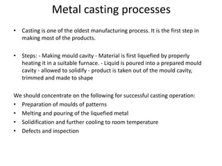
  • 1. Metal casting processes • Casting is one of the oldest manufacturing process. It is the first step in making most of the products. • Steps: - Making mould cavity - Material is first liquefied by properly heating it in a suitable furnace. - Liquid is poured into a prepared mould cavity - allowed to solidify - product is taken out of the mould cavity, trimmed and made to shape We should concentrate on the following for successful casting operation: • Preparation of moulds of patterns • Melting and pouring of the liquefied metal • Solidification and further cooling to room temperature • Defects and inspection
  • 2. Advantages • Molten material can flow into very small sections so that intricate shapes can be made by this process. As a result, many other operations, such as machining, forging, and welding, can be minimized. • Possible to cast practically any material: ferrous or non-ferrous. • The necessary tools required for casting moulds are very simple and inexpensive. As a result, for production of a small lot, it is the ideal process. • There are certain parts (like turbine blades) made from metals and alloys that can only be processed this way. Turbine blades: Fully casting + last machining. • Size and weight of the product is not a limitation for the casting process.
  • 3. Limitations • Dimensional accuracy and surface finish of the castings made by sand casting processes are a limitation to this technique. • Many new casting processes have been developed which can take into consideration the aspects of dimensional accuracy and surface finish. Some of these processes are die casting process, investment casting process, vacuum-sealed moulding process, and shell moulding process. • Metal casting is a labour intensive process
  • 4. Pattern • A Pattern is a model or the replica of the object to be cast. • Except for the various allowances a pattern exactly resembles the casting to bemade. • Patterns may be in two or three pieces, where as casting are in a single piece. • A pattern is required even if one object has to be cast. • The quality of casting and the final product will be effected to a great extent by theplanning of pattern. • A Pattern prepares a mould cavity for the purpose of making a casting. • A Pattern may contain projections known as core prints if the casting requires a coreand need to be made hollow. • Risers, runnersand gates may form a part of the pattern. • Patterns properly made and having finished and smooth surfaces reduce castingdefects. • Properly constructed patterns minimize overall cost of the casting.
  • 5. Selection of Pattern Materials The following factors assist in selecting proper pattern material: • No. of castings to be produced. • Metal to be cast. • Dimensional accuracy & surface finish. • Shape, complexity and size of casting. • Casting design parameters. • Type of molding materials. • The chance of repeat orders. • Nature of molding process. • Position of core print.
  • 6. Materials for making patterns: • Wood • Metal • Plastic • Plaster • Wax.
  • 7. Wood Patterns These are used where the no. of castings to be produced is small and pattern size is large. Advantages: • Inexpensive • Easily available in largequantities • Easy tofabricate • Light inweight • They can be repairedeasily • Easy to obtain good surfacefinish
  • 8. Limitations • Susceptible to shrinkage andswelling • Possess poor wearresistance • Abraded easily by sandaction • Absorb moisture, consequently getwrapped • Cannot withstand roughhandling • Life is veryshort Commonly used woods for makingpatterns: • Teak • Pine • Mahogony • Deodaretc..
  • 9. Metal Patterns These are employed where large no. of castings have to be produced from same patterns. Advantages: • Do not absorbmoisture • Morestronger • Possess much longerlife • Do not wrap, retain theirshape • Greater resistance to abrasion • Accurate and smooth surfacefinish • Good machinability
  • 10. Limitations • Expensive • Require a lot of machining foraccuracy • Not easilyrepaired • Ferrous patterns getrusted • Heavyweight , thusdifficult to handle Commonly used metals for makingpatterns: • Cast iron • Aluminium and itsalloys • Steel • White metal • Brass etc..
  • 11. Plastic Patterns Advantages: • Durable • Provides a smoothsurface • Moisture resistant • Does not involve anyappreciablechange in size or shape • Lightweight • Good strength • Wear and corrosionresistance • Easy tomake • Abrasion resistance • Good resistance to chemicalattack Limitations: • Plastic patterns areFragile • These are may not work well when subject to conditions of severe shock as in machine molding(jolting).
  • 12. Plaster Patterns Advantages: • It can be easilyworked by using wood working tools. • Intricate shapes can be cast without anydifficulty. • It has high compressivestrength. Limitations: • Brittle in nature • Plaster maybe made out of Plaster of parisor Gypsumcement. • Plaster mixture is poured into a mould made by a sweep pattern or a wooden master pattern, in order to obtain a Plasterpattern.
  • 13. Wax patterns Advantages: • Provide very good surfacefinish. • Impart high accuracy tocastings. • After being molded, the wax pattern is not taken out of the mould like otherpatterns; rather the mould is inverted and heated; the molten wax comes out and/or isevaporated. • Thus there is nochance of the mould cavity getting damaged while removing thepattern. • Wax patterns find applications in Investment casting process.
  • 14. Difference Between Pattern and Cast Pattern is a replica of the final object to be made with some modifications. The mould cavity is made with the help of the pattern. Afterwards the mould cavity will be filled with molten metal. After solidification the object will be removed from the cavity and that solidified metal object is called casting.
  • 15. Types of Patterns Types of patterns depend upon the following factors: • The shape and size ofcasting • No. of castingsrequired • Method of mouldingemployed • Anticipated difficulty of mouldingoperation
  • 16. Types of Patterns • Single piecepattern. • Split piecepattern. • Loose piecepattern. • Match platepattern. • Sweeppattern. • Gated pattern. • Skeleton pattern • Follow board pattern. • Cope and Dragpattern.
  • 17. Single piece (solid) pattern: • Made from one piece and does notcontain loosepieces or joints. • Inexpensive. • Used for large size simplecastings. • Pattern is accommodated either in the copeor in the drag. Examples: • Bodies of regularshapes. • stuffling box of steamengine.
  • 18. Fig: Single piece pattern
  • 19. Split piece pattern • Patterns of intricate shaped castings cannot be made in one piece because of the inherent difficulties associated with the molding operations (e.g. withdrawing pattern frommould). • The upper and the lower parts of the split piece patterns are accommodated in the cope and drag portions of the mold respectively. • Parting line of the pattern forms the parting line of the mould. • Dowel pins are used for keeping the alignment between the two partsof the pattern. Examples: • Hallow cylinder • Taps and water stop cocksetc.,
  • 20.
  • 21. Loose piece pattern • Certain patterns cannot be withdrawn once they are embedded in the molding sand. Such patterns are usually made with one or more loose pieces for facilitating from the molding box and are known as loose piecepatterns. • Loose parts or pieces remain attached with the main body of the pattern, with the help of dowel pins. • The main body of the pattern is drawn first from the molding box and thereafter as soon as the loose parts are removed, the result is the mold cavity.
  • 22.
  • 23. Match plate pattern • It consists of a match plate, on either side of which each half of split patterns isfastened. • A no. of different sized and shaped patterns may be mounted on one matchplate. • The match plate with the help of locator holes can be clamped with the drag. • After the cope and drag have been rammed with the molding sand, the match plate pattern is removed from in between the cope anddrag. • Match plate patterns are normally used in machine molding. • By using this wecan eliminate mismatch of copeand drag cavities.
  • 24. Fig: Match plate pattern
  • 25. Sweep pattern • A sweep pattern is just a form made on a wooden board which sweeps the shape of the casting into the sand all around the circumference. The sweep pattern rotates about thepost. • Once the mold is ready, Sweep pattern andthe post can beremoved. • Sweep pattern avoids the necessity of making a full, large circular and costlythree-dimensional pattern. • Making a sweep pattern saves a lot of time and labour as compared to making a fullpattern. • A sweep pattern is preferred for producing large casting of circular sections and symmetrical shapes.
  • 26.
  • 27. Gated pattern • The sections connecting different patterns serveas runner andgates. • This facilitates filling of the mould with molten metal in a better manner and at the same time eliminates the time and labour otherwise consumed in cutting runners andgates. • A gated pattern can manufacture many casting at one time and thus it is used in mass production systems. • Gated patterns are employed for producing small castings.
  • 29. Skeleton pattern • A skeleton pattern is the skeleton of a desired shape which may be S- bend pipe or a chute or something else. The skeleton frame is mounted on a metal base • The skeleton is made from woodenstrips, and is thus a woodenwork. • The skeleton pattern is filled with sand and is rammed. • A strickle (board) assists in giving the desired shape to the sand and removes extrasand. • Skeleton patterns are employed forproducing a few largecastings. • A skeleton pattern is very economical, because it involves less materialcosts.
  • 30.
  • 31. Follow board pattern • A follow board is a wooden board and is used for supporting a pattern which is very thin and fragile and which may give way and collapse underpressure when the sand above the pattern is being rammed. • With the follow board support under the weak pattern, the drag is rammed, and then the fallow board is with drawn, The rammed drag isinverted, cope is mounted on it andrammed. • During this operation pattern remains over the inverted drag and get support from the rammed sand of the drag underit. • Follow boards are also used for casting master patterns for manyapplications.
  • 32.
  • 33. Cope and Drag patterns • A copeand drag pattern is another form of split pattern. • Each half of the pattern is fixed toa separate metal/wood plate. • Each half of the pattern(along the plate) is molded separately in a separate molding box byan independent molder ormoulders. • The two moulds of each half of the pattern are finally assembled and the mould is ready forpouring. • Cope and drag patterns are used for producing big castings which as a whole cannot be conveniently handled by one moulderalone.
  • 34. Fig: Cope and drag pattern
  • 35. Pattern Allowances A pattern is larger in size as compared to the final casting, because it carries certain allowances due to metallurgical and mechanical reasons for example, shrinkage allowance is the result of metallurgical phenomenon where as machining, draft, distortion, shake and other allowances are provided on the patterns because of mechanicalreasons.
  • 36. Types of Pattern Allowances The various pattern allowances are: • Shrinkage or Contraction allowance • Machining or finishallowance. • Draft of tapperallowances. • Distortion or chamberallowance. • Shake or rappingallowance.
  • 37. Shrinkage Allowance • Almost all cast metals shrink or contract volumetrically after solidification and therefore the pattern to obtain a particular sized casting is made oversize by an amount equal to thatof shrinkage orcontraction. • Different metals shrink at different rates because shrinkage is the property of thecast metal/alloy. Liquid Shrinkage: • it refers to the reduction in volume when the metal changes from liquid state to solid state at the solidus temperature. To account for this shrinkage; riser, which feed the liquid metal to the casting, are provided in the mold. Solid Shrinkage: • it refers to the reduction in volume caused when metal loses temperature in solid state. To account for this, shrinkage allowance is provided on the patterns.
  • 38. The metal shrinkage depends upon: • The cast metal or alloy. • Pouring temp. of the metal/alloy. • Casted dimensions(size). • Casting designaspects. • Molding conditions(i.e., mould materials and molding methods employed)
  • 39. The contraction of metals/alloys is always volumetric, but the contraction allowances are always expressed in linear measures.
  • 40. Machining Allowance • Castings get oxidized in the mold and during heat treatment; scales etc., thus formed need to be removed. • It is the intended to remove surface roughness and other imperfections from thecastings. • It is required toachieve exact casting dimensions. • Surface finish is required on thecasting.
  • 41. How much extra metal or how much machining allowance should be provided, depends on the factors listed below: • Nature of metals. • Size and shape ofcasting. • The type of machining operations tobe employed for cleaning thecasting. • Casting conditions. • Molding processemployed
  • 42. Machining Allowances of Various Metals
  • 43. Draft or Taper Allowance • It is given to all surfaces perpendicularto parting line. • Draft allowance is given so that the pattern can be easily removed from the molding material tightly packedaround it with out damaging the mould cavity. • The amount of taper dependsupon: • Shape and size of pattern in the depth direction in contact with the mouldcavity. • Moulding methods. • Mould materials. • Draft allowance is imparted on internal as well as external surfaces; of course it is more on internal surfaces.
  • 44. The taper provided by the pattern maker on all vertical surfaces of the pattern so that it can be removed from the sand without tearing away the sides of the sand mold and without excessive rapping by the molder. Figure 3 (a) shows a pattern having no draft allowance being removed from the pattern. In this case, till the pattern is completely lifted out, its sides will remain in contact with the walls of the mold, thus tending to breakit.
  • 45. Figure 3 (b) is an illustration of a pattern having proper draft allowance. Here, the moment the pattern lifting commences, all of its surfaces are well away from the sand surface. Thus the pattern can be removed without damaging the moldcavity.
  • 46.
  • 47. Fig: taper in design
  • 48. Distortion or cambered allowance • It is of irregularshape, • All it parts do not shrink uniformly i.e., some parts shrinks while others are restricted from during so, It is u or v-shape, • The arms possess unequal thickness, • It has long, rangy arms as thoseof propeller shaft for theship, • It is a long flatcasting, One portion of thecasting coolsat a faster rate as compared to theother.
  • 49.
  • 50.
  • 51. Shake allowance • A patter is shaken or rapped by striking the same with a wooden piece from side to side. This is done so that the pattern a little is loosened in the mold cavityand can be easilyremoved. • In turn, therefore, rapping enlarges the mould cavity which results in a bigger sizedcasting. • Hence, a –ve allowance is provided on the pattern i.e., the pattern dimensions are kept smaller in order to compensate the enlargement of mould cavitydue to rapping. • The magnitude of shake allowance can be reduced by increasing the tapper.
  • 52. Pattern Layout Steps involved: • Get the working drawing of the part for which the pattern is to be made. • Make two views of the part drawing on a sheet, using a shrink rule. A shrink rule is modified form of an ordinary scale which has already taken care of shrinkage allowance fora particularmetal to be cast. • Add machining allowancesas per the requirements. • Depending upon the method of molding, providethe draftallowance.
  • 53. Pattern Construction • Study the pattern layout carefully and establish, • Location of partingsurface. • No. of parts in which the pattern willbe made. • Using the various hand tools and pattern making machines fabricate the different parts of the pattern. • Inspect the pattern as regards the alignment of different portions of the pattern and itsdimensional accuracy. • Fill wax in all the fillets in order to remove sharp corners. • Give a shellaccoatings(3 coats) to pattern. • impart suitable colors to the pattern for identification purposes and for otherinformations.
  • 54. Pattern Colors Patterns are imparted certain colors and shades in order to: • Identify quickly the main body of pattern and different parts of thepattern. • Indicate the typeof the metal to becast. • Identify core prints, loose pieces,etc., • Visualize thesurfaces to be machined, etc.
  • 55. The patterns are normally painted with contrasting colors such that the mould maker would be able to understand the functions clearly. The color code used is, • Red ororangeon surface not to be finished and left as cast • Yellow on surfaces to bemachined • Black on coreprints forunmachined openings • Yellow stripes on black on core prints for machinsed openings • Green on seats of and for loose pieces and loose coreprints • Diagonal black strips with clear varnish on to strengthen the weak patterns or to shorten a casting.
  • 56. Properties of Foundary Sand The moulding sand should have: • Good flowability, • Green strength, • Dry strength, • Hot strength, • Permeability, • Refractoriness, • Adhesiveness, • Cohesiveness, • Collapsibility, • Fineness, • Bench life, • Coefficient of expansion, • Durability.
  • 57. Ingredients used in sand for making moulds/cores • Refractory sand grains: Silica, Magnesite, Dolomite, Coke, Carbon • Binder: Clay and others • Facing Material: Sea coal, Pitch, Graphite • Cusion Material: Wood Flour, Cereal Hull, Perlite
  • 58.
  • 59. Natural and Synthetic molding sand Natural molding sand: This is ready for use as it is dug from the ground. Good natural molding sand are obtained from Albany, New york etc. The following average compositions are seen in natural molding sand: 65.5% silica grains, 21.7% clay content, 12.8% undesirable impurities. Too much clay content and other impurities fill up the gaps between the sand grains. This will hinder the necessary passage of steam and other gases during pouring of the mold. • Advantages of natural molding sand: 1. moisture content range is wide, 2. molds can be repaired easily Synthetic molding sand Synthetic molding sand is made by mixing together specially selected high quality clay free silica, with about 5% of clay. They are tailor made to give most desirable results. Some of the advantages of synthetic molding sand are: • 1.Refractory grain sizes are more uniform, 2. Higher refractoriness (= 30000F), 3. less bonding agent is required (about 1/3rd of the clay percentage found in natural molding sand), 4. More suitable for use with mechanical equipment
  • 60. Sand testing Criteria used for sand testing: • Moisture content, • Green and dry sand permeabilities, • Compression, • Tension, • Transverse and shear strengths, • Deformation during compression tests, • Green and dry hardness, • Clay content, • Grain-size distribution, • Combustible content, • Pressure, • Volume of gases evolved, • Flowability, • Sintering point, • Resistance to Breaking etc.
  • 61. Moulding sand preparation and moisture content determination: The moisture content controls practically all other properties of the sand. It is a varying property since water content constantly evaporates during mold preparation. Purpose: adding sufficient water to bring the moisture content to within desired limits, uniform distribution of water, adequate coating of colloidal clay to each sand grain. Moisture content determination: • The simplest method is to dry a sample thoroughly at a few degrees above 212oF and to consider its loss in weight as moisture. • Drying can be done in a thermostatically controlled oven or in a instrument designed for this purpose • There is one MOISTURE TELLER which blows air through a 50 gm sample of sand that is placed in a plate.
  • 62. Testing rammed sand • Green permeability, green compression and few other properties are tested when the sand is in rammed condition. • The rammed densities should be within some range which is actually encountered in the sand molds • A predetermined weight of sand is placed into the hardened steel tube, which is closed at the bottom by a pedestal actually the tube filled with sand and the pedestal are weighed • The entire set up is placed into the sand rammer and the rammer is dropped few times depending on particular standards, like three times etc.
  • 63. • The weight used will be a standard one. Depending on the ramming times, a standard density is obtained. • Once the ramming is completed, the height of the rammed sand is evaluated and this should be equal to 2 inches in length. If it is equal to this height, required density is expected to be in the rammed sand. • If the sand height is outside the range, the entire procedure will be repeated.
  • 64.
  • 65. Permeability Test During the solidification of a casting, large amount of gases are to be expelled out from the mould. The gases are those which are absorbed by the metal in the furnace, air absorbed from the atmosphere, steam and other gases that are generated by the moulding and core sands. If these gases are not allowed to escape from the mould, they could be trapped inside the casting, causing defects. The moulding sand should be sufficiently porous, so that the gases are allowed to escape from the mould. This gas evolution capability of the moulding sand is termed as permeability. • Keep the pressure Valve in D Position. • Place the sand specimen at specified place in inverted position. • Fill water in the large vessel upto 3/4th of the volume. • Insert the upper jar such like the the 0 line on the upper jar should exactly matches the lower jar top periphery (volume of the air trapped between it is 2000cc). • Turn the valve from D position to O position. This will bring a locking position for the upper jar. • Fill some water in the manometer tube so that it touches the 0 position in the scale.
  • 66. • Turn the valve to P position; this makes the air to flow through the sand specimen. • Pass the air till the upper jar comes down to the level of lower jar. • Start the stop watch to note down the time to pass 2000cc of air from the specimen. • After full air pass turn the valve to D position. • Remove the specimen with the help of removing rod. • Permeability (P) = 𝑽𝑯 𝒑𝑨𝑻 • V = Volume of the air passing through the specimen in cc i.e. 2000cc • H = Height of the specimen in cm = 50.8mm • p = pressure of air in g/cm2 • A = cross section area of the specimen in cm2 (d = 50mm) • T = time in minutes.
  • 67. Green compression strength • The sand specimen is compressed between two plates connected to the ram of the universal testing machine. The load at which the sand sample breaks will give the compression strength. The same tests can be performed at high temperatures in furnaces to find the compression strength at elevated temperatures.