Pneumatic control valve
•Transferir como PPT, PDF•
12 gostaram•4,658 visualizações

Pneumatic control valve Actual Pneumatic Control Valve Typical Actuator & Valve introduction to actuator Actuator power Actuator Fluids Diaphragm Actuator Positioner Indicator Valve Body Valve Plugs Reverse & Direct Actuators Air-To-Open vs. Air-To-Close control valve Controller Tuning Selection of controller modes Tuning Rules Ziegler – Nichols Controller Settings

Recomendados
Mais conteúdo relacionado
Mais procurados
Mais procurados (20)
Semelhante a Pneumatic control valve
Semelhante a Pneumatic control valve (20)
Mais de Karnav Rana
Mais de Karnav Rana (20)
Último
Último (20)
Pneumatic control valve
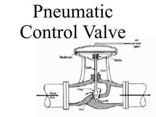
- 2. Introduction to Pneumatic Control Valve •A valve in which the force of compressed air against a diaphragm is opposed by the force of a spring to control the area of opening for a fluid stream. •It consist of an actuator and a valve. •The actuator moves the valves stem as the pressure on a spring loaded diaphragm changes.
- 5. Actual Pneumatic Control Valve
- 6. Typical Actuator & Valve
- 7. INTRODUCTION TO ACTUATOR •Actuator converts the command signal from controllers or higher-level components into physical adjustment in adjustable process variable.
- 8. Actuator •It convert controller output signal (4-20 mA or 3-15 psig) to physical adjustment in the process input variables. •For process control, the most common type of actuator is the control valve. •Others include – Variable speed pumps – Hydraulic actuators
- 9. Actuator power •Pneumatic: simple, low cost, fast, low torque •Electric: motor and gear box, high torque, slow •Hydraulic: high torque, fast, expensive
- 10. Actuator Fluids •Air •Oil (mineral and synthetic) which is Clean & Moisture Free
- 13. Valve Body
- 14. Valve Plugs
- 15. Reverse & Direct Actuators CloseOpen
- 16. Reverse & Direct Actuators
- 17. Air-To-Open vs. Air-To-Close •Air-to-Open (+ gain) More air →larger opening No air → Valve closes. •Air-to-Close (- gain) More air →smaller opening No air → Valve opens completely. •Proper type to use is determined from safety considerations •Air-to-close: Coolant valve in an exothermic reactor or in a condenser of a distillation column. •Air-to-open: Steam valve in a reactor, inlet flow valve to a tank.
- 18. Failure Mode
- 19. CONTROL VALVE • Valve+Actuator - Valve opening is adjusted by an actuator • Pneumatic Control Valve – Usually 3~15 psig signal is provided. – I/P transmitter converts 4~20mA signal to 3~15 psig pneumatic signal via 20psig supply air.
- 20. Useful definitions • Cycle time — Also known as duty cycle; the total length of time for the controller to complete one on/off cycle. Example: with a 20 second cycle time, an on time of 10 seconds and an off time of 10 seconds represents a 50 percent power output. The controller will cycle on and off while within the proportional band. • Proportional band — A temperature band expressed in degrees (if the input is temperature), or counts (if the input is process) from the set point in which the controllers’ proportioning action takes place. The wider the proportional band the greater the area around the set point in which the proportional action takes place. It is sometimes referred to as gain, which is the reciprocal of proportional band.
- 21. •Integral, also known as reset, is a function which adjusts the proportional bandwidth with respect to the set point, to compensate for offset (droop) from set point, that is, it adjusts the controlled temperature to set point after the system stabilizes. •Derivative, also known as rate, senses the rate of rise or fall of system temperature and automatically adjusts the proportional band to minimize overshoot or undershoot.
- 22. Controller Tuning •The adjustment of control parameters to achieve satisfactory control is called Tuning. •The process of tuning can vary from trial-and-error to an elaborate optimization calculation. •A typical criteria for good control is that the response of the system to a step change in set point or load should have minimum overshoot and one quarter decay ratio.
- 23. Selection of controller modes •P (Proportional Control) •PD (Proportional Derivative Control) •PID (Proportional Integral Derivative Control)
- 24. Load response of typical control system using various modes of control
- 25. Tuning Rules • Ziegler – Nicholas Rules (Z - N) • It’s a closed loop tuning system as the controller remains in the loop as an active controller in automatic mode. 1. After the process reaches a steady state at normal level of operation, remove integral and derivative modes of controller, leaving only proportional control. On some PID controllers this requires that the integral time (τ1) be set to its maximum value and derivative time (τD) to its min. value.
- 26. Tuning Rules 2. Select a value of proportional gain (Kc), disturb the system and observe the transient response. If the response decays select a higher value of Kc and again observe the response of the system. Continue increasing the gain in small steps until the response first exhibits a sustained oscillation. The value of gain and period of oscillation that correspond to the sustained oscillation are the ultimate gain (Kcu) and ultimate period (Pu). 3. From the values of (Kcu) & (Pu). Find controller settings Kc, τ1, τD
- 27. • Ku = 1/A ( Over all gain is A at the crossover frequency) • Pu = 2pi/wc0 time/cycle (wc0 Crossover frequency)
- 28. Ziegler – Nichols Controller Settings Type of control Gc(s) Kc τ1 τD Proportional (P) Kc 0.5Ku Proportional-Integral (PI) Kc( 1 + 1/ τ1 s ) 0.45Ku Pu 1.2 Proportional-Integral –Derivative (PID) Kc( 1 + 1/ τ1 s + τDs ) 0.6Ku Pu 2 Pu 8