
Recomendados
Mais conteúdo relacionado
Mais procurados
Mais procurados (20)
Semelhante a MAQUINARIA IGSA POWER GENERATION SYSTEMS MODEL: GSJD10200M
Semelhante a MAQUINARIA IGSA POWER GENERATION SYSTEMS MODEL: GSJD10200M (20)
Último
Último (20)
MAQUINARIA IGSA POWER GENERATION SYSTEMS MODEL: GSJD10200M
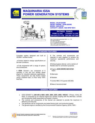
- 1. MAQUINARIA IGSA POWER GENERATION SYSTEMS MODEL: GSJD10200M DIESEL ENGINE: JOHN DEERE MODEL: 6081AF001 CAPACITY: 200kW; 1800 RPM TIER I RATINGS RANGE PRIME hp (kW) STANDBY hp (kW) 229-238 (171-178) 256-268 (191-200) Note: Gross power guaranteed within + or – 5% ISO 3046 conditions: 77°F (25°C) Air inlet temperature 29.31 in.Hg(99KPa) Barometer 104 °F (40°C) fuel inlet temperature 0.853 fuel specific gravity @ 60°F (15.5 °C) STANDARD FEATURES Complete system designed and built at 2 The controls and accessories are ISO9001 certified facility selected to work together to achieve the maximum operational performance and ● Factory tested to design specifications at security. full load conditions. 3 Exhaust gases silencer, and a section of ● Fully engineered with a range of options flexible tube for connection purposes. and accessories. 4 Engine JOHN DEERE 6081AF001 1 IGSA Genset´s are composed of 6 TIER I cylinders in line and four strokes diesel engine for industrial stationary applications. 5 Alternator Those equipments are fully factory tested using a resistive load. (1) Hour ramp 100% 6 Radiator load test. 7 Control MEC 310 (panel USC300) 8 Base of structural steel GENERAL FEATURES • IGSA GENSET of, 200 kW to 480V, 440V, 380V, 220V, 208V, 190VAC 3 Phase, 4 Wire, 60 Hertz, is composed by an internal engine four strokes coupling with the alternator, controls and accessories totally assembled and tested in factory. • The controls and accessories of the Genset are selected to provide the maximum in efficiency and Security • The generator set its components are tested factory-built, and production-tested. • The genset engine is certified by the Environmental Protection Agency (EPA) TIER I www.igsa.com.mx All rights reserved. WE ARE THE BEST IN MANUFACTURING THE POWER GENERATION Printed in MEXICO SYSTEMS AND ADDITION CONSTANTLY INNOVATION. 1-7 Materials and specifications are subject to change without notice. The International System of Units (Sl) is used in this publication.
- 2. ENGINE SPECIFICATION DATA MODEL 6081AF001 weight 796 kg (1755Lb) General Data Electrical System Model 6081AF001 Recommended Battery Capacity (CCA) Number of Cylinders 6 12 Volt System--amp 800 Bore and Stroke--in.(mm) 4.56 x 5.06 (116 x 129) 24 Volt System--amp 570 Displacement--in.3 (L) 496 (8.1) Maximum Allowable Starting Circuit Resistane Compression Ratio 16.5 : 1 12 Volt System--Ohm 0.0012 Valves per Cylinder--Intake/Exhaust 1/1 24 Volt System--Ohm 0.002 Firing Order 1-5-3-6-2-4 Starter Rolling Current -- 12 Volt System Combustion System Direct Injection At 32 F (0 C) -- amp 950 Engine Type In-line, 4-Cycle At -22 F (-30 C) -- amp 1300 Aspiration Turbocharged Starter Rolling Current -- 12 Volt System Engine Crankcase Vent System Open At 32 F (0 C) -- amp 600 Maximum Crankcase Pressure--in.H2O (kPa) 2 (0.5) At -22 F (-30 C) -- amp 700 Physical Data Lubrication System Prime Standby Length--in.(mm) 47.6 (1210) Oil Pressure at Rated Speed--psi (kPa) 40 (275) 40 (275) Width--in.(mm) 27.5 (698) Oil Pressure at Low Idle--psi (kPa) 30 (210) 30 (210) Height--in.(mm) 44.8 (1138) In Pan Oil Temperature--°F (°C) 240 (115) 240 (115) Weight, dry--lb (kg) 1755 (796) Oil Pan Capacty, High--qt (L) 32.75 (31) 32.75 (31) (Includes SAE 4 flywheel housing, RE28119 flywheel, Oil Pan Capacty, Low--qt (L) 31.75 (30) 31.75 (30) starter and electrics.) Total Engine Oil Capacity ----- ----- Center of Gravity Location Eng. Oil Capacity with Filters—qt(L) 33.75 (32) 33.75 (32) From Rear Face of Block (X-axis)--in.(mm) 19.2 (482) Engie Angularity Limits Right of Crankshaft (Y-axis)--in.(mm) -0.09 (-24) (Continuous) Any Direction--degrees 20 20 Above Crankshaft (Z-axis)--in.(mm) 5.7 (45) Exhaust System Prime Standby Max. Allow. Static Bending Moment at Rear Exhaust Flow--ft3/min (m3/min) 1560(44.2) 1695(48) Face of Flywhl Hsg w/ 5-G Load--lb-ft (N•m) 600 (814) Exhaust Temperature--°F (°C) 1017 (547) 1020 (550) Thrust Bearing Load Limit (Forward) Max. Allow. Back Press.--in.H2O (kPa) 30 (7.5) 30 (7.5) Continuous--lb (N) 1950 (8673) Recm’d Exhaust Pipe Dia--in.(mm) 4 (101.6) 4 (101.6) Intermittent--lb (N) 2925 (13010) Cooling System Prime Standby Performance Data Prime Standby Engine Heat Reject.--BTU/min (kW) 6530 (115) 7390 (130) 229-238 256-268 Rated Power--hp (kW) (171-178) (191-200) Coolant Flow--gal/min (L/min) 71 (270) 71 (270) Rated Speed--rpm 1800 1800 Thermostat Start to Open--°F (°C) 180 (82) 180 (82) Low Idle Speed--rpm 850 850 Thermostat Fully Open--°F (°C) 202 (94) 202 (94) BMEP--psi (kPa) 222 (1530) 266 (1835) Maximum Water Pump Friction Power Inlet Restriction--in.H2O (kPa) 27 (7) 27 (7) At Rated Speed--hp (kW) 28 (21) 28 (21) Engine Coolant Capacity--qt (L) 16 (15) 16 (15) Altitude Capability--ft (m) 7500 (2300) 5000 (1500) Recm’d Pressure Cap--psi (kPa) 10 (69) 10 (169) Ratio--Air : Fuel. 26.2:1 25.0:1 Maximum Top Tank Temp--°F (°C) 221 (105) 221 (1105) Noise--dB(A) @ 1 m 96.0 97.5 Min. Coolant Fill Rate--gal/min (L/min) 3 (11) 3 (11) Air System Prime Standby Min. Air-to-Boil Temperature--°F (°C) 117 (47) 117 (47) Maximum Allowable Temp Rise--Ambient Air to Fuel System Prime Standby Engine Inlet--°F (°C) 15 (8) 15 (8) Fuel Injection Pump RB P7100 RB P7100 Maximum Air Intake Restriction Governor Regulation 5% 5% Dirty Air Cleaner--in.H2O (kPa) 25 (6.25) 25 (6.25) Governor Type Mechanical Mechanical Clean Air Cleaner--in.H2O (kPa) 12 (3) 12 (3) Total Fuel Flow--lb/hr (kg/hr) 460 (209) 460 (209) Engine Air Flow--ft3/min (m3/min) 591 (16.8) 635 (18) Fuel Consumption--lb/hr (kg/hr) 92.2 (41.9) 102.3(46.5) Intake Manifold Pressure--psi (kPa) 22.5 (155) 26.1 (180) Maximum Fuel Transfer Pump Suction ft (m) fuel 10 (3.0) 10 (3.0) Rec’d. Intake Pipe Dia--in.(mm) 4 (102) 4 (102) Fuel Filter Micron Size @ 98 % Efficiency 8 8 Fuel Consumption -- lb/hr (kg/hr) Prime Standby 25 % Power 26.3 (11.9) 29.7 (13.5) 50 % Power 46.9 (21.3) 51.7 (23.5) 75 % Power 68.8 (31.2) 77.0 (35.0) 100 % Power 90.7 (1.1) 102.3(46.5) www.igsa.com.mx All rights reserved. WE ARE THE BEST IN MANUFACTURING THE POWER GENERATION Printed in MEXICO SYSTEMS AND ADDITION CONSTANTLY INNOVATION. 2-7 Materials and specifications are subject to change without notice. The International System of Units (Sl) is used in this publication.
- 3. MARATHON ELECTRIC ALTERNATOR MODEL 431PSL6206 weight 1205 kg (2657Lb) Kilowatt ratings at 1800 RPM 60 Hertz 12 Leads standard 3 phase kW (kVA) 3 Phase 0.8 Power Factor Dripproof or Open Enclousure Class B Class F Class H 105°C-221ºF † 125°C-257ºF † Voltage 80°C -176ºF (1) 90°C-194º F(1) 95°C-203ºF(1) British 105°C-221ºF (1) 130°C-282ºF(1) British 125°C-257ºF (1) 150°C-302ºF (1) Continuous Lloyds ABS Standard Continuous Standby Standard Continuous Standby 240/480 165 (206) 180 (225) 186 (233) 200 (250) 200 (250) 215 (269) 205 (256) 211 (264) 225 (281) 230/460 170 (213) 185 (231) 190 (238) 200 (250) 200 (250) 220 (275) 205 (256) 215 (269) 225 (281) 220/440 172 (215) 185 (31) 191 (239) 200 (250) 200 (250) 220 (275) 205 (256) 212 (265) 226 (283) 208/416 170 (213) 180 (225) 183 (229) 191 (239) 191 (239) 210 (263) 197 (246) 202 (253) 217 (271) 190/380 156 (195) 165 (206) 170 (213) 176 (220) 176 (220) 191 (239) 182 (228) 185 (231) 200 (250) (1)Rise by resistance method, Mil-Std-705, Method 680.1b. † Rating per BS 5000. Submittal Data: 240/480 Volts, 250 kVA, 1800 RPM, 60 Hz, 3 Phase Mil-Std-705C Mil-Std-705C Method Description Value Method Description Value 301.1b Insulation Resistance > 1.5 Meg 505.3b Overspeed 2250 RPM 302.1a High Potential Test 507.1c Phase Sequence CCW-ODE ABC Main Stator 2000 Volts 508.1c Voltage Balance L-L OR L-N 0.2% Main Rotor 1500 Volts 601.4a L-L Harmonic Maximum - Total 5.0% Exciter Stator 1500 Volts (Distortion Factor) Exciter Rotor 1500 Volts 601.4a L-L Harmonic Maximum - Single 3.0% 401.1a Stator Resistance, Line to Line 601.1c Deviation Factor 5.0% High Wye Connection 0.0371 Ohms -- TIF (1960 Weightings) <50 Rotor Resistance 0.679 Ohms 625.1c Mechanical Strength (High wye Exciter Stator 18.5 Ohms Conection, sustained 3 Phase Exciter Rotor 0.116 Ohms Short Circuit Current) <300% 410.1a No Load Exciter Field Amps -- THF (IEC, BS & NEMA Weightins) <2% at 480 Volts Line to Line 0.6 A DC 652.1a Shaft Current <0.1 ma 420.1a Short Circuit Ratio 0.53 652.2a Main Stator Capacitance to ground @0.011 mfd 421.1a Xd Synchronous Reactance 2.766 pu 422.1a X2 Negative Sequence Additional Prototype Mil-Std Methods Rectance 0.188 pu are Available on Request. 423.1a X0 Zero Sequence Reactance 0.037 pu 425.1a X'd Transient Reactance 0.141 pu -- Generator Frame 431 426.1a X''d Subtransient Reactance 0.138 pu -- Type Ext. Voltage Regulated, Brushless 427.1a T'd Transient Short Circuit -- Insulation Class H Time Constant 0.061 sec. -- Coupling - Single Bearing Flexible 428.1a T''d Subtransient Short Circuit -- Amortisseur Windings Full Time Constant 0.019 sec. -- Cooling Air Volume 1200 CFM 430.1a T'do Transient Open Circuit -- Exciter Rotating Time Constant 1.02 sec. -- Voltage Regulator SE350*** 432.1a Ta Short Circuit Time -- Voltage Regulation 1%*** Constant of Armature Winding 0.019 sec. -- Sensing 1 Phase*** * (3) Excitation support system or PMG required to sustain short circuit currents. * Voltage refers to wye (star) connection, unless otherwise specified. ** Not supplied as standard equipment. *** DVR®2000 voltage regulator supplied with PMG option. DVR®2000 voltage regulation ¼% I or 3 Phase sensing www.igsa.com.mx All rights reserved. WE ARE THE BEST IN MANUFACTURING THE POWER GENERATION Printed in MEXICO SYSTEMS AND ADDITION CONSTANTLY INNOVATION. 3-7 Materials and specifications are subject to change without notice. The International System of Units (Sl) is used in this publication.
- 4. STAMFORD ELECTRIC ALTERNATOR MODEL UCI274H weight 613 kg (1352Lb) CONTROL SYSTEM SEPARATELY EXCITED BY P.M.G. A.V.R. MX321 MX341 VOLTAGE REGULATION (+/- 0.5%) (+/- 1.0%) WITH 4% ENGINE GOVERNING SUSTAINED SHORT CIRCUIT REFERENT TO SHOT CIRCUIT DECREMENT CURRENT INSULATION SYSTEM CLASS H PROTECTION IP23 RATED POWER FACTOR 0.8 STATOR WINDING DOUBLE LAYER CONCENTRIC WINDING PITCH TWO THIRDS WINDING LEADS 12 STATOR WDG. RESISTANCE 0.0155 Ohms PER PHASE AT 22°C SERIES STAR CONNECTED ROTOR WDG. RESISTANCE 1.82 Ohms at 22°C R.F.I. SUPPRESSION BS EN 61000-6-2 & BS EN 61000-6-4,VDE 0875G, VDE 0875N. refer to factory for others WAVEFORM DISTORTION NO LOAD < 1.5% NON-DISTORTING BALANCED LINEAR LOAD < 5.0% MAXIMUM OVERSPEED 2250 Rev/Min BEARING DRIVE END BALL. 6315 - 2RS. (ISO) BEARING NON-DRIVE END BALL. 6310 - 2RS. (ISO) 1 BEARING 2 BEARING WEIGHT COMP. GENERATOR 626 kg 641 kg WEIGHT WOUND STATOR 253 kg 253 kg WEIGHT WOUND ROTOR 227.53 Kg 216.57 kg WR² INERTIA 1.9349 kgm2 1.8843 kgm2 SHIPPING WEIGHTS in a crate 659 kg 673 kg PACKING CRATE SIZE 123 x 67 x 103 (cm) 123 x 67 x 103 (cm) 50 Hz 60 Hz THF<2% TIF<50 TELEPHONE INTERFERENCE COOLING AIR 0.514 m³/sec 1090 cfm 0.617 m³/sec 1308 cfm VOLTAGE SERIES STAR 380/220 400/231 415/240 440/254 416/240 440/254 460/266 480/277 VOLTAGE PARALLEL STAR 190/110 200/115 208/120 220/127 208/120 220/127 230/133 240/138 VOLTAGE SERIES DELTA 220/110 230/115 240/120 254/127 240/120 254/127 266/133 277/138 kVA BASE RATING FOR 200 200 200 N/A 273.5 245 245 255 RECTANCE VALUES Xd DIR. AXIS SYNCHRONOUS 2.11 1.91 1.77 N/A 2.50 2.31 2.11 2.02 X'd DIR. AXIS TRANSIENT 0.18 0.16 0.15 - 0.21 0.19 0.18 0.17 X''d DIR. AXIS SUBTRANSIENT 0.12 0.11 0.10 - 0.14 0.13 0.12 0.11 Xq QUAD. AXIS REACTANCE 1.28 1.15 1.07 - 1.53 1.41 1.29 1.23 X''q QUAD. AXIS SUBTRANSIENT 0.17 0.15 0.14 - 0.20 0.18 0.17 0.16 XL LEAKAGE REACTANCE 0.08 0.08 0.07 - 0.10 0.09 0.08 0.08 X2 NEGATIVE SEQUENCE 0.13 0.12 0.11 - 0.16 0.15 0.13 0.13 X0 ZERO SEQUENCE 0.08 0.08 0.07 - 0.10 0.09 0.08 0.08 REACTANCES ARE SATURATED VALUES ARE PER UNIT AT RATING AND VOLTAGE INDICATED T'd TRANSIENT TIME CONST. 0.042 s T''d SUB-TRANSTIME CONST. 0.012 s T'do O.C. FIELD TIME CONST. 1.1 s Ta ARMATURE TIME CONST. 0.012 s SHORT CIRCUIT RATIO 1/Xd RATINGS: All three-phase units are rated at 0.8 power factor. All single-phase units are rated at 1.0 power factor. Standby Ratings: Standby ratings apply to installations served by a reliable utility source. The standby rating is applicable to varying loads for the duration of a power outage. There is no overload capability for this rating. Ratings are in accordance with ISO-3046/1, BS5514, AS2789, and DIN 6271. Prime Power Ratings: Prime power ratings apply to installations where utility power is unavailable or unreliable. At varying load, the number of generator set operating hours is unlimited. A 10% overload capacity is available for a 12 hour period. Ratings are in accordance with ISO- 8528/1, overload power in accordance with ISO-3046/1, BS 5514, AS 2789, and DIN 6271. For limited running time and base load ratings, consult the factory. The generator set manufacturer reserves the right to change the design or specifications without notice and without any obligation or liability whatsoever. GENERAL GUIDELINES FOR DERATION: Altitude: Derate 1.3% per 100 m (328 ft.) elevation above 2000 m (6560 ft.). Temperature: Derate 1.0% per 10°C (18°F) temperature above 40°C (104°F). www.igsa.com.mx All rights reserved. WE ARE THE BEST IN MANUFACTURING THE POWER GENERATION Printed in MEXICO SYSTEMS AND ADDITION CONSTANTLY INNOVATION. 4-7 Materials and specifications are subject to change without notice. The International System of Units (Sl) is used in this publication.
- 5. CONTROLLER FOR GENSET: CONTROL MEC 310 PANEL USC300 The Generator Controller MEC 310 is a microprocessor-based control unit containing all necessary functions for protection and control of a power generator. Besides the control and protection of the diesel engine it contains a full 3-phase AC voltage and current measuring circuit. The unit is equipped with an LCD display presenting all values and alarms. o AC Protective Relaying: o 27/59 Under/Over Voltage o 32 Reverse Power o 51 Time Overcurrent o 81 O/U Under/Over Frequency o Digital gauge display: o Oil Pressure (sender required by others) o Coolant Temperature (sender required by others) o Fuel Level (sender required by others) o Hourmeter o Tachometer • 5 digital inputs for alarms / shutdowns • Dedicated Output Contacts - Engine Crank; Run (30 VDC / 6 Amps) • USC 300C Unit Mount Control • Three Programmable Output Panel, Black Nema 1 enclosure c/w Contacts (30 VDC / 1 Amps) rubber mounts • Event Logging (30 events) • MEC 310 Microprocessor Based • Pushbuttons: Engine Generator Controller • Emergency Stop • Graphic Display 128 X 64 pixels • Manual Start and Stop (STN) Super Twisted Nematic • Manual/Auto/Test • Digital AC Metering: • Lamp Test o 3-Phase Volts (Phase to • Horn Silence Phase and Phase to • Indicating Lights: Neutral), • Common Alarm o 3-Phase Amps • Generator Ready (Voltage and o Frequency Frequency Normal) o kW, kVAR, KVA, pF, kWHr FEATURES Electrical Rating: - Single or three phase, 600VAC maximum, 50/60HZ, 4 wire - 12 or 24Vdc (nominal) supply, negative ground. - Dedicated Output Contacts - Engine Crank; Run (30 VDC / 6 Amps) - Three Programmable Output Contacts (30 VDC / 1 Amps) Enclosure: - Black Nema 1 enclosure c/w rubber mounts Engine Senders: - Oil pressure (1/8” NPT), Temperature (1/4”NPT) (Supplied loose for engine mounting). Requirements: - Exceeds requirements of CSA 282 and NFPA 110 Level www.igsa.com.mx All rights reserved. WE ARE THE BEST IN MANUFACTURING THE POWER GENERATION Printed in MEXICO SYSTEMS AND ADDITION CONSTANTLY INNOVATION. 5-7 Materials and specifications are subject to change without notice. The International System of Units (Sl) is used in this publication.
- 6. OPTIONAL SILENCER ACCORDING TO THE APPLICATION Silencer with different levels from attenuation • Critical Grade • Super Critical Grade • Hospital Grade Levels from attenuation DOCUMENTATION AND OTHERS • Manual of operation and maintenance • Spare parts • Maintenance • Consulting MISCELLANEOUS EQUIPMENT • Batteries of 12 VDC with cables for battery connection with the Engine. GENSET OPTIONS OPTIONAL ACCESSORIES AVAILABLE FOR THE EQUIPMENT Control Panel USC 300C Control Panel is standard on all units see Vibration isolation page 4 of spec sheet for standard features. Another Type___________________________ Rigid Spring Mounting Fuel system Resilient Mounting antifreeze Fuel Water Separator Filters Day tank Air Filter for Medium Dust Environments Auxiliary fuel pump Air Filter of Heavy Dust Environments Sub Base mounted Fuel Tank Single Wall Drain Double Wall Oil drain Extension UL listed 150 L (39.6 gal) Enclosures 250 L (66 gal) Sound Attenuated Weather Proof Diesel Fuel Tank Stainless steel cover 500 L (132 gal) Trailer Mounting 1000 L (264.1 gal) Interior lights Ac or DC 5000 L (1320.8 gal) Heaters Jacket Water Heater Exhaust System Crankcase Oil Heater Critical Grade Insulation Blankets Super Critical Grade Features: Hospital Grade ( Temperature to 1260°C (2300°F), Non- Combustible, Highly Resistant to Engine Electrical system Vibration, Oil, Fuel, Grease, and Moisture Battery Resistant Exterior, Personal Protection Notes Lead-Acid NiCad _______________________________ Battery Rack Battery Charger Automatic _______________________________ _______________________________ Generator _______________________________ Breaker in the alternator www.igsa.com.mx All rights reserved. WE ARE THE BEST IN MANUFACTURING THE POWER GENERATION Printed in MEXICO SYSTEMS AND ADDITION CONSTANTLY INOVATION. 6-7 Materials and specifications are subject to change without notice. The International System of Units (Sl) is used in this publication.
- 7. DIMENSIONS LENGTH WIDTH HEIGHT mm (in) mm (in) mm (in) 2600(102.36 1000(39.36) 1609(63.33) NOTE: General configuration not to be used for installation. See general dimension drawing for detail. SERVICES • Development of the project. • Development of engineering. • Equipment’s Installation • Engineering for special applications. • Synchronies with utility network or more Gensets. • Attention and technical support INSTALLATION OPTIONS OF THE GENSET • On-Site • Acoustic Enclosure • ISO Container • Trailer www.igsa.com.mx All rights reserved. WE ARE THE BEST IN MANUFACTURING THE POWER GENERATION Printed in MEXICO SYSTEMS AND ADDITION CONSTANTLY INOVATION. 7-7 Materials and specifications are subject to change without notice. The International System of Units (Sl) is used in this publication.