
Recomendados
Recomendados
Mais conteúdo relacionado
Último
Último (20)
Destaque
Destaque (20)
2008 Pontiac G8 Service Repair Manual
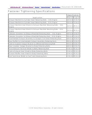
- 1. 2009 Pontiac G8 | G8 Service Manual | Engine | Engine Exhaust | Specifications | Document ID: 2043445 Fastener Tightening Specifications Application Specification Metric English Exhaust Manifold to Cylinder Head Retaining Bolts - 3.6L Engine 20 N·m 15 lb ft Exhaust Manifold to Cylinder Head Retaining Bolts - 6.0L Engine 20 N·m 15 lb ft Exhaust Manifold Heat Shield to Exhaust Manifold Retaining Bolts - 3.6L Engine 10 N·m 89 lb in Exhaust Manifold Heat Shield to Exhaust Manifold Retaining Bolts - 6.0L Engine 10 N·m 89 lb in Catalytic Converter to Exhaust Manifold Retaining Nuts - 3.6L Engine 45 N·m 33 lb ft Catalytic Converter to Exhaust Manifold Retaining Nuts - 6.0L Engine 45 N·m 33 lb ft Intermediate Exhaust Assembly to Catalytic Converter Retaining Nuts 40 N·m 30 lb ft Rear Muffler to Intermediate Exhaust Assembly Retaining Nuts 45 N·m 33 lb ft Centre Insulator Hanger Bracket to Differential Retaining Bolt 45 N·m 33 lb ft Rear Insulator Hanger Bracket to Body Retaining Bolts 26 N·m 19 lb ft Front Exhaust Foil Heat Shield to Body Retaining Bolt 4 N·m 35 lb in Centre Exhaust Heat Shield to Body Retaining Bolts 4 N·m 35 lb in Exhaust Muffler Heat Shield to Body Retaining Bolts 4 N·m 35 lb in Fuel Tank Heat Shield to Fuel Tank Retaining Nuts 4 N·m 35 lb in © 2010 General Motors Corporation. All rights reserved. Page 1 of 1Document ID: 2043445 2/19/2010http://localhost:9001/si/showDoc.do?docSyskey=2043445&pubCellSyskey=37862&pubO...
- 2. 2009 Pontiac G8 | G8 Service Manual | Engine | Engine Exhaust | Repair Instructions | Document ID: 2099997 Exhaust System Alignment Warning: Refer to Exhaust Service Warning in the Preface section. Caution: Refer to Exhaust System Inspection Caution in the Preface section. Note: This procedure is only to be performed if the exhaust is incorrectly aligned or is not clear of all other components or chassis. Note: Make sure all exhaust retaining nuts and bolts are loose before conducting this procedure. Note: The L98 exhaust is pictured but flange bolts are in the same location on LY7. Caution: Refer to Fastener Caution in the Preface section. 1. Initially tighten catalytic converter to exhaust manifold retaining nuts (1) to 20 N·m (15 lb ft). 2. Tighten catalytic converter to exhaust manifold retaining nuts (1) to 45 N·m (33 lb ft). 3. Tighten exhaust crossover pipe to catalytic converter retaining nuts (2) to 40 N·m (30 lb ft). 4. Tighten muffler to exhaust crossover pipe retaining bolts (3) to 45 N·m (33 lb ft). © 2010 General Motors Corporation. All rights reserved. Page 1 of 1Document ID: 2099997 2/19/2010http://localhost:9001/si/showDoc.do?docSyskey=2099997&pubCellSyskey=169436&pub...
- 3. 2009 Pontiac G8 | G8 Service Manual | Engine | Engine Exhaust | Repair Instructions | Document ID: 2193215 Exhaust Manifold Replacement - Left Side (V8) Removal Procedure Warning: Refer to Exhaust Service Warning in the Preface section. Warning: Refer to Protective Goggles and Glove Warning in the Preface section. 1. Ignition OFF. Warning: Refer to Battery Disconnect Warning in the Preface section. 2. Disconnect the battery negative cable. Refer to Battery Negative Cable Disconnection and Connection. 3. Remove the engine cover. Refer to Engine Cover Replacement. 4. Remove the air cleaner assembly. Refer to Air Cleaner Assembly Replacement. 5. Remove the left side spark plug leads. Refer to Spark Plug Replacement. 6. Remove the left side spark plugs from the cylinder head. Refer to Exhaust Manifold Heat Shield Replacement - Right Side. 7. Remove the left side exhaust manifold heat shield. Refer to Exhaust Manifold Heat Shield Replacement - Left Side. 8. Remove the engine coolant temperature sensor. Refer to Engine Coolant Temperature Sensor Replacement. Note: The left catalytic converter to exhaust manifold retaining nuts (2) are single use parts. They must be discarded after removal. 9. Remove the left catalytic converter to exhaust manifold retaining nuts (2). Discard the nuts. © 2010 General Motors Corporation. All rights reserved. Page 1 of 4Document ID: 2193215 2/19/2010http://localhost:9001/si/showDoc.do?docSyskey=2193215&pubCellSyskey=62243&pubO...
- 4. 10. Disconnect the left catalytic converter (3) from the exhaust manifold (4). 11. Loosen the exhaust manifold to cylinder head retaining bolts (1) working from the outside to the centre. Note: Bolts with micro-encapsulated thread sealant must be discarded after removal. 12. Remove the exhaust manifold to cylinder head retaining bolts (1). Discard the bolts. Note: Make sure that the surrounding wiring harness and electrical connectors are not damaged when removing the exhaust manifold (2). Note: The exhaust manifold gasket (1) and sealing ring (3) are single use parts. They must be discarded after removal. 13. Remove the exhaust manifold (2). Discard the exhaust manifold gasket (1) and sealing ring (3). Installation Procedure 1. Clean and inspect the exhaust manifold. Refer to Exhaust Manifold Cleaning and Inspection. Page 2 of 4Document ID: 2193215 2/19/2010http://localhost:9001/si/showDoc.do?docSyskey=2193215&pubCellSyskey=62243&pubO...
- 5. 2. Install a NEW exhaust manifold gasket (1) and NEW sealing ring (3) to the exhaust manifold (2). Caution: Refer to Exhaust System Inspection Caution in the Preface section. 3. Install the exhaust manifold assembly to the engine. 4. Install the NEW exhaust manifold to cylinder head retaining bolts (1). Caution: Refer to Fastener Caution in the Preface section. 5. Tighten the exhaust manifold to cylinder head retaining bolts (1) working from the centre to the outside to 20 N·m (15 lb ft). Page 3 of 4Document ID: 2193215 2/19/2010http://localhost:9001/si/showDoc.do?docSyskey=2193215&pubCellSyskey=62243&pubO...
- 6. Note: Make sure the sealing ring is seated correctly. 6. Lift the left catalytic converter (3) up and forward to connect to the exhaust manifold (4). 7. Clean the threads of the exhaust manifold to catalytic converter retaining studs with a suitable cleaning solvent. 8. Install the NEW left catalytic converter to exhaust manifold retaining nuts (2) and tighten to 45 N·m (33 lb ft). 9. Install the engine coolant temperature sensor. Refer to Engine Coolant Temperature Sensor Replacement. 10. Remove the install the left side exhaust manifold heat shield. Refer to Exhaust Manifold Heat Shield Replacement - Left Side. 11. Install the left side spark plugs to the cylinder head. Refer to Spark Plug Replacement. 12. Install the left side spark plug leads. Refer to Spark Plug Wire Inspection. 13. Install the air cleaner assembly. Refer to Air Cleaner Assembly Replacement. 14. Install the engine cover. Refer to Engine Cover Replacement. 15. Connect the battery negative cable. Refer to Battery Negative Cable Disconnection and Connection. Page 4 of 4Document ID: 2193215 2/19/2010http://localhost:9001/si/showDoc.do?docSyskey=2193215&pubCellSyskey=62243&pubO...
- 7. 2009 Pontiac G8 | G8 Service Manual | Engine | Engine Exhaust | Repair Instructions | Document ID: 2195070 Exhaust Manifold Replacement - Left Side (V6) Removal Procedure Warning: Refer to Exhaust Service Warning in the Preface section. Warning: Refer to Protective Goggles and Glove Warning in the Preface section. 1. Ignition OFF. Warning: Refer to Battery Disconnect Warning in the Preface section. 2. Disconnect the battery negative cable. Refer to Battery Negative Cable Disconnection and ConnectionBattery Negative Cable Disconnection and Connection. 3. Remove the engine cover. Refer to Engine Cover Replacement. 4. Remove the left pre-catalytic convertor heated oxygen sensor (HO2S). Refer to Heated Oxygen Sensor Replacement - Bank 2 Sensor 1. 5. Remove the exhaust manifold heat shield. Refer to Exhaust Manifold Heat Shield Replacement - Left Side . 6. Remove the oil level indicator tube. Refer to Oil Level Indicator and Tube Removal . 7. Remove the left catalytic converter. Refer to Catalytic Converter Replacement - Left Side . 8. Remove the battery positive cable retaining nut (1) from the starter motor solenoid. 9. Remove the battery positive cable (2) from the starter motor. © 2010 General Motors Corporation. All rights reserved. Page 1 of 6Document ID: 2195070 2/19/2010http://localhost:9001/si/showDoc.do?docSyskey=2195070&pubCellSyskey=62243&pubO...
- 8. Note: Bolts with micro-encapsulated thread sealant must be discarded after removal. 10. Remove the exhaust manifold to cylinder head retaining bolts (1). Discard the bolts. Warning: Refer to Safety Glasses Warning in the Preface section. Danger: To avoid any vehicle damage, serious personal injury or death, always use the jackstands to support the vehicle when lifting the vehicle with a jack. 11. Raise and support the vehicle. Refer to Lifting and Jacking the Vehicle. Page 2 of 6Document ID: 2195070 2/19/2010http://localhost:9001/si/showDoc.do?docSyskey=2195070&pubCellSyskey=62243&pubO...
- 9. Note: Bolts with micro-encapsulated thread sealant must be discarded after removal. 12. Remove the exhaust manifold to cylinder head retaining bolts (1). Discard the bolts. Note: Make sure that the surrounding wiring harness and electrical connectors are not damaged when removing the exhaust manifold (2). Note: The exhaust manifold gasket (1) and sealing ring (3) are single use parts. They must be discarded after removal. 13. Remove the exhaust manifold (2) from the engine assembly. 14. Separate the exhaust manifold (2) from the exhaust manifold gasket (1) and sealing ring (3). 15. Discard the exhaust manifold gasket (1) and sealing ring (3). Installation Procedure Caution: Refer to Exhaust System Inspection Caution in the Preface section. 1. Inspect the exhaust manifold before installation. Refer to Exhaust Manifold Cleaning and Inspection - Left Side. Page 3 of 6Document ID: 2195070 2/19/2010http://localhost:9001/si/showDoc.do?docSyskey=2195070&pubCellSyskey=62243&pubO...
- 10. Note: Make sure the sealing ring is seated correctly. 2. Install a NEW exhaust manifold gasket (1) and NEW sealing ring (3) to the exhaust manifold (2). Warning: Refer to Safety Glasses Warning in the Preface section. Danger: To avoid any vehicle damage, serious personal injury or death, always use the jackstands to support the vehicle when lifting the vehicle with a jack. 3. Raise and support the vehicle. Refer to Lifting and Jacking the Vehicle. Note: A suitable support must be used to support the exhaust manifold while the vehicle is being lowered. 4. Install the exhaust manifold assembly (2) to the engine. Page 4 of 6Document ID: 2195070 2/19/2010http://localhost:9001/si/showDoc.do?docSyskey=2195070&pubCellSyskey=62243&pubO...
- 11. Note: Do not fully tighten the exhaust manifold to cylinder head retaining bolts (1) at this stage. 5. Install NEW exhaust manifold to cylinder head retaining bolts (1). Caution: Refer to Fastener Caution in the Preface section. 6. Tighten the exhaust manifold to cylinder head retaining bolts (1) working from the centre to the outside to 20 N·m (15 lb ft). 7. Lower the vehicle. Note: Do not fully tighten the exhaust manifold to cylinder head retaining bolts (1) at this Page 5 of 6Document ID: 2195070 2/19/2010http://localhost:9001/si/showDoc.do?docSyskey=2195070&pubCellSyskey=62243&pubO...
- 12. stage. 8. Install NEW exhaust manifold to cylinder head retaining bolts (1). 9. Tighten the exhaust manifold to cylinder head retaining bolts (1) working from the centre to the outside to 20 N·m (15 lb ft). 10. Install the battery positive cable (2) to the starter motor. 11. Install the battery positive cable retaining nut (1) to the starter motor solenoid and tighten to 10 N·m (89 lb in). 12. Install the left catalytic converter. Refer to Catalytic Converter Replacement - Left Side . 13. Install the exhaust manifold heat shield. Refer to Exhaust Manifold Heat Shield Replacement - Left Side . 14. Install the left pre-catalytic convertor HO2S. Refer to Heated Oxygen Sensor Replacement - Bank 2 Sensor 1 . 15. Install the engine cover. Refer to Engine Cover Replacement. 16. Connect the battery negative cable. Refer to Battery Negative Cable Disconnection and Connection . Page 6 of 6Document ID: 2195070 2/19/2010http://localhost:9001/si/showDoc.do?docSyskey=2195070&pubCellSyskey=62243&pubO...
- 13. 2009 Pontiac G8 | G8 Service Manual | Engine | Engine Exhaust | Repair Instructions | Document ID: 2193216 Exhaust Manifold Replacement - Right Side (V8) Removal Procedure Warning: Refer to Exhaust Service Warning in the Preface section. Warning: Refer to Protective Goggles and Glove Warning in the Preface section. 1. Ignition OFF. Warning: Refer to Battery Disconnect Warning in the Preface section. 2. Disconnect the battery negative cable. Refer to Battery Negative Cable Disconnection and Connection. 3. Remove the engine cover. Refer to Engine Cover Replacement. 4. Remove the oil level indicator tube. Refer to Oil Level Indicator Tube Replacement. 5. Remove the right side spark plug leads. Refer to Spark Plug Wire Replacement. 6. Remove the right side spark plugs from the cylinder head. Refer to Spark Plug Replacement. 7. Remove the right side exhaust manifold heat shield. Refer to Exhaust Manifold Heat Shield Replacement - Right Side. Note: The right catalytic converter to exhaust manifold retaining nuts (1) are single use parts. They must be discarded after removal. 8. Remove the right catalytic converter to exhaust manifold retaining nuts (1). Discard the nuts. 9. Disconnect the right catalytic converter (4) from the exhaust manifold (3). 10. Loosen the exhaust manifold to cylinder head retaining bolts (2) working from the outside to© 2010 General Motors Corporation. All rights reserved. Page 1 of 4Document ID: 2193216 2/19/2010http://localhost:9001/si/showDoc.do?docSyskey=2193216&pubCellSyskey=62244&pubO...
- 14. the centre. Note: Bolts with micro-encapsulated thread sealant must be discarded after removal. 11. Remove the exhaust manifold to cylinder head retaining bolts (2). Discard the bolts. Note: Make sure that the surrounding wiring harness and electrical connectors are not damaged when removing the exhaust manifold (2). Note: The exhaust manifold gasket (1) and sealing ring (3) are single use parts. They must be discarded after removal. 12. Remove the exhaust manifold (2). Discard the exhaust manifold gasket (1) and sealing ring (3). Installation Procedure 1. Clean and inspect the exhaust manifold. Refer to Exhaust Manifold Cleaning and Inspection. Page 2 of 4Document ID: 2193216 2/19/2010http://localhost:9001/si/showDoc.do?docSyskey=2193216&pubCellSyskey=62244&pubO...
- 15. 2. Install NEW exhaust manifold gasket (1) and NEW sealing ring (3) to the exhaust manifold (2). Caution: Refer to Exhaust System Inspection Caution in the Preface section. 3. Install the exhaust manifold assembly to engine. 4. Install the NEW exhaust manifold to cylinder head retaining bolts (1). Caution: Refer to Fastener Caution in the Preface section. 5. Tighten the exhaust manifold to cylinder head retaining bolts (2) working from the centre to the outside to 20 N·m (15 lb ft). Page 3 of 4Document ID: 2193216 2/19/2010http://localhost:9001/si/showDoc.do?docSyskey=2193216&pubCellSyskey=62244&pubO...
- 16. Note: Make sure the sealing ring is seated correctly. 6. Lift the right catalytic converter (4) up and forward to connect to the exhaust manifold (3). 7. Clean the threads of the exhaust manifold to catalytic converter retaining studs with a suitable cleaning solvent. 8. Install the NEW right catalytic converter to exhaust manifold retaining nuts (1) and tighten to 45 N·m (33 lb ft) 9. Install the right side exhaust manifold heat shield. Refer to Exhaust Manifold Heat Shield Replacement - Right Side. 10. Install the right side spark plugs to the cylinder head. Refer to Spark Plug Replacement. 11. Install the right side spark plug leads. Refer to Spark Plug Wire Inspection. 12. Install the oil level indicator tube. Refer to Oil Level Indicator Tube Replacement. 13. Install the engine cover. Refer to Engine Cover Replacement. 14. Connect the battery negative cable. Refer to Battery Negative Cable Disconnection and Connection. Page 4 of 4Document ID: 2193216 2/19/2010http://localhost:9001/si/showDoc.do?docSyskey=2193216&pubCellSyskey=62244&pubO...
- 17. 2009 Pontiac G8 | G8 Service Manual | Engine | Engine Exhaust | Repair Instructions | Document ID: 2195071 Exhaust Manifold Replacement - Right Side (V6) Removal Procedure Warning: Refer to Exhaust Service Warning in the Preface section. Warning: Refer to Protective Goggles and Glove Warning in the Preface section. 1. Ignition OFF. Warning: Refer to Battery Disconnect Warning in the Preface section. 2. Disconnect the battery negative cable. Refer to Battery Negative Cable Disconnection and ConnectionBattery Negative Cable Disconnection and Connection. 3. Remove the engine cover. Refer to Engine Cover Replacement. 4. Remove the right pre-catalytic convertor heated oxygen sensor (HO2S). Refer to Heated Oxygen Sensor Replacement - Bank 1 Sensor 1. 5. Remove the exhaust manifold heat shield. Refer to Exhaust Manifold Heat Shield Replacement - Right Side . 6. Remove the right catalytic converter. Refer to Catalytic Converter Replacement - Right Side . Note: Bolts with micro-encapsulated thread sealant must be discarded after removal. 7. Remove the exhaust manifold to cylinder head retaining bolts (1). Discard the bolts. Warning: Refer to Safety Glasses Warning in the Preface section. Danger: To avoid any vehicle damage, serious personal injury or death, always use the jackstands to support the vehicle when lifting the vehicle with a jack.© 2010 General Motors Corporation. All rights reserved. Page 1 of 5Document ID: 2195071 2/19/2010http://localhost:9001/si/showDoc.do?docSyskey=2195071&pubCellSyskey=62244&pubO...
- 18. 8. Raise and support the vehicle. Refer to Lifting and Jacking the Vehicle. Note: Bolts with micro-encapsulated thread sealant must be discarded after removal. 9. Remove the exhaust manifold to cylinder head retaining bolts (1). Discard the bolts. Note: Make sure that the surrounding wiring harness and electrical connectors are not damaged when removing the exhaust manifold (2). Page 2 of 5Document ID: 2195071 2/19/2010http://localhost:9001/si/showDoc.do?docSyskey=2195071&pubCellSyskey=62244&pubO...
- 19. Note: The exhaust manifold gasket (1) and sealing ring (3) are single use parts. They must be discarded after removal. 10. Remove the exhaust manifold (2) from the engine assembly. 11. Separate the exhaust manifold (2) from the exhaust manifold gasket (1) and sealing ring (3). 12. Discard the exhaust manifold gasket (1) and sealing ring (3). Installation Procedure Caution: Refer to Exhaust System Inspection Caution in the Preface section. 1. Inspect the exhaust manifold before installation. Refer to Exhaust Manifold Cleaning and Inspection - Right Side. Note: Make sure the sealing ring is seated correctly. 2. Install a NEW exhaust manifold gasket (1) and NEW sealing ring (3) to the exhaust manifold (2). Warning: Refer to Safety Glasses Warning in the Preface section. Danger: To avoid any vehicle damage, serious personal injury or death, always use the jackstands to support the vehicle when lifting the vehicle with a jack. 3. Raise and support the vehicle. Refer to Lifting and Jacking the Vehicle. Note: A suitable support must be used to support the exhaust manifold while the vehicle is being lowered. 4. Install the exhaust manifold assembly (2) to the engine. Page 3 of 5Document ID: 2195071 2/19/2010http://localhost:9001/si/showDoc.do?docSyskey=2195071&pubCellSyskey=62244&pubO...
- 20. Note: Do not fully tighten the exhaust manifold to cylinder head retaining bolts (1) at this stage. 5. Install NEW exhaust manifold to cylinder head retaining bolts (1). Caution: Refer to Fastener Caution in the Preface section. 6. Tighten the exhaust manifold to cylinder head retaining bolts (1) working from the centre to the outside to 20 N·m (15 lb ft). 7. Lower the vehicle. Note: Do not fully tighten the exhaust manifold to cylinder head retaining bolts (1) at this Page 4 of 5Document ID: 2195071 2/19/2010http://localhost:9001/si/showDoc.do?docSyskey=2195071&pubCellSyskey=62244&pubO...
- 21. stage. 8. Install NEW exhaust manifold to cylinder head retaining bolts (1). 9. Tighten the exhaust manifold to cylinder head retaining bolts (1) working from the centre to the outside to 20 N·m (15 lb ft). 10. Install the right catalytic converter. Refer to Catalytic Converter Replacement - Right Side . 11. Install the exhaust manifold heat shield. Refer to Exhaust Manifold Heat Shield Replacement - Right Side . 12. Install the right pre-catalytic convertor HO2S. Refer to Heated Oxygen Sensor Replacement - Bank 1 Sensor 1 . 13. Install the engine cover. Refer to Engine Cover Replacement . 14. Connect the battery negative cable. Refer to Battery Negative Cable Disconnection and Connection . Page 5 of 5Document ID: 2195071 2/19/2010http://localhost:9001/si/showDoc.do?docSyskey=2195071&pubCellSyskey=62244&pubO...
- 22. 2009 Pontiac G8 | G8 Service Manual | Engine | Engine Exhaust | Repair Instructions | Document ID: 2193589 Exhaust Crossover Pipe Replacement (V8) Removal Procedure Warning: Refer to Exhaust Service Warning in the Preface section. Warning: Refer to Protective Goggles and Glove Warning in the Preface section. 1. Ignition OFF. Warning: Refer to Battery Disconnect Warning in the Preface section. 2. Disconnect the battery negative cable. Refer to Battery Negative Cable Disconnection and Connection. Danger: To avoid any vehicle damage, serious personal injury or death when major components are removed from the vehicle and the vehicle is supported by a hoist, support the vehicle with jack stands at the opposite end from which the components are being removed and strap the vehicle to the hoist. 3. Raise and support the vehicle. Refer to Lifting and Jacking the Vehicle. 4. Remove the right post-catalytic converter heated oxygen sensor (HO2S). Refer to Heated Oxygen Sensor Replacement - Bank 1 Sensor 2. 5. Remove the left post-catalytic converter HO2S. Refer to Heated Oxygen Sensor Replacement - Bank 2 Sensor 2. 6. Support the exhaust system using a suitable jack. Note: The exhaust crossover pipe assembly to left catalytic converter retaining nuts (3) are single use parts. They must be discarded after removal. © 2010 General Motors Corporation. All rights reserved. Page 1 of 9Document ID: 2193589 2/19/2010http://localhost:9001/si/showDoc.do?docSyskey=2193589&pubCellSyskey=37841&pubO...
- 23. 7. Remove the exhaust crossover pipe assembly to left catalytic converter retaining nuts (3). Discard the nuts. Note: The exhaust crossover pipe assembly to right catalytic converter retaining nuts (3) are single use parts. They must be discarded after removal. 8. Remove the exhaust crossover pipe assembly to right catalytic converter retaining nuts (3). Discard the nuts. 9. Separate the exhaust crossover pipe assembly (2) from the catalytic converter assemblies. Page 2 of 9Document ID: 2193589 2/19/2010http://localhost:9001/si/showDoc.do?docSyskey=2193589&pubCellSyskey=37841&pubO...
- 24. 10. Remove the transmission tunnel cross-brace to body retaining bolts (2). 11. Remove the transmission tunnel cross-brace (1). 12. Remove the exhaust crossover pipe assembly to left rear muffler retaining bolts (3). 13. Disconnect the left rear muffler (1) from the exhaust crossover pipe assembly (2). 14. Remove the exhaust crossover pipe assembly to right rear muffler retaining bolts (3). 15. Disconnect the right rear muffler (1) from the exhaust crossover pipe assembly (2). Page 3 of 9Document ID: 2193589 2/19/2010http://localhost:9001/si/showDoc.do?docSyskey=2193589&pubCellSyskey=37841&pubO...
- 25. 16. Detach the exhaust system (2) by removing the front insulator hangers (1). 17. Remove the centre insulator hanger bracket to differential retaining nut (1). 18. Detach the exhaust crossover pipe assembly from the centre insulator hanger to differential retaining stud (1). 19. With the aid of an assistant or using a suitable jack; carefully lower the exhaust system from the vehicle. Installation Procedure Caution: Refer to Exhaust System Inspection Caution in the Preface section. 1. Clean all threads and flange faces of the exhaust crossover pipe assembly. 2. Replace the catalytic converter to exhaust crossover pipe assembly flange gaskets. Page 4 of 9Document ID: 2193589 2/19/2010http://localhost:9001/si/showDoc.do?docSyskey=2193589&pubCellSyskey=37841&pubO...
- 26. Thank you very much for your reading. Please Click Here Then Get More Information.