
Recomendados
Recomendados
Mais conteúdo relacionado
Mais procurados
Mais procurados (20)
Semelhante a ABC in Nebraska: Belden to Laurel Bridge
Semelhante a ABC in Nebraska: Belden to Laurel Bridge (20)
Mais de Jill Reeves
Mais de Jill Reeves (20)
Último
Último (20)
ABC in Nebraska: Belden to Laurel Bridge
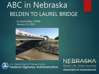
- 1. ABC in Nebraska BELDEN TO LAUREL BRIDGE by David Mraz, FHWA January 22, 2019
- 4. Old Bridge •3 Span Steel Girder – 100’ total •Original Construction 1938. Widened in 1972 •Scour issues temporarily repaired in 2013 •Deck test in 2005 shows high chlorides
- 5. Belden-Laurel Objectives •Expand on PBES technology previously done in Kearney • Add precast rails to precast deck panels • Simplify deck-to-girder connections • Provide non-post-tensioned option using UHPC •Utilize new ABC features • Precast abutment caps • Precast wing walls • Precast grade beams • Precast approach slabs •Minimize road closure period
- 6. New Bridge • Simple Span NU 1100 – 130’
- 7. Element Fabrication • 7 NU1100 Girders • 22 Full-depth deck panels with Rail • 2 Abutment Cap • 2 Backwalls • 4 Wing Walls • 2 Grade Beams • 8 Approach Slabs
- 8. Bridge Construction • Assembling prefabricated elements: •Abutment Caps •Grade Beams •Wing Walls •Prestressed Concrete Girders •Deck Panels with Rail •Approach Slabs •Connecting elements using CIP: •Self-Consolidating Concrete (SCC) •Ultra-High Performance Concrete (UHPC) •High-Early Strength Concrete (HESC)
- 9. Substructure Plan View of Abutment Cap, Wing Wall, and Grade Beam
- 10. Elevation View of Abutment Cap
- 11. Cross Section of Abutment CAP at CMP
- 22. Superstructure
- 26. Shear Pocket
- 28. NU Deck Panel Longitudinal Rebar Lap Transverse Rebar Lap Rail
- 37. Shear Connector
- 39. Haunch
- 40. Typical Girder Cross Section
- 46. 1. Fill Longitudinal Joint above Girder D with HESC 2. Fill Remaining Girder Haunches with SCC 3. Fill Transverse Joints with UHPC Sequence for Filling Joints Between NU Deck Panels
- 50. Filling Joints Between Approach and Paving Panels 1. Fill Transverse Joint at End of Floor with UHPC 2. Fill Pockets above Grade Beam with SCC 3. Fill Longitudinal Joints with SCC
- 51. Approach and Paving Section Longitudinal Joint on Paving and Approach Slabs
- 52. Approach Section to NU Deck Panel Connection at End of Floor
- 53. Bridge Joint Nosing Material (possible future use)
- 58. Answer to the Question •Yes– FHWA Nebraska Division Office hopes to see NDOT use ABC for more bridge replacements projects.
- 59. Thank You!
Notas do Editor
- What is ABC? ABC stands for Accelerated Bridge Construction. A technology that Federal Highway has been promoting heavily the last ten years or so around the country. In ABC technology, bridges can be built under three construction methods, 1) is (Prefabricated Bridge Element Systems) PBES, 2) Slide in Bridge Construction (SIBC), and 3) Geosynthetics Reinforced Soil (GRS). Nebraska has experimented with using two of these methods (PBES and GRS), and the hope is Nebraska will experiment with a bridge slide very soon. Each of these methods is supposed to reduce road closure time to less 30 days and make more durable bridges with longer service lives than conventional bridges. In this presentation, we are going to discuss an ABC project that NDOT did recently using the PBES method. This method is where all the members of the bridge are fabricated off sight somewhere (this includes the piles, abutment caps, backwall, wingwalls, grade beams, girders, deck, approach slabs, and bridge rail), then all the bridge elements are assembled quickly in the field to make the new bridge. Nebraska DOT has been perfecting the use of ABC technology with the (PBES) method. Do I believe NDOT is ready to use this technology at bridge locations where it makes sense? Well, together let’s see if we can answer that question as we look at a recent bridge replacement project NDOT did last summer.
- First some acknowledgements, the bridge project was built by Simon and the fabricator was Concrete Industries, Werner Construction was the prime contractor.
- The ABC bridge project was called the Belden – Laurel, which are two small towns on US 20 in Cedar County, Nebraska.
- Here is a photo of the old structure. As you can see, it is a three span steel girder bridge with a total length of 100 feet over a creek. The bridge was originally constructed in 1938 and widened in 1972. The bridge had scour issues but those were addressed in 2013. The bridge deck test from 2005 showed the deck had high chlorides. A bridge with high chloride concentration in the deck, as you know, indicates deterioration will take place rapidly and will need be replaced soon.
- NDOT did a partial PBES type bridge project in Kearney, Nebraska few years ago. It was NDOTs desire to improve on some the PBES technology used on the Kearney bridge project. So one of the main objectives was to make improvements on the Kearney bridge project by 1) add precast rails to precast deck panels, 2) simplify deck to girder connections, 3) provide a non-post-tensioned option using UHPC Another objective to make the Belden bridge project a true ABC bridge project using the PBES method of construction by using precast abutments, wing walls, grade beams, and approach slabs. The final objective was to make this bridge project to have traffic closed on US 20 for no more than 30 days. For the paving folks, I hope to leave you with some take aways.
- Here is the new proposed bridge. A single span 130’ foot prestressed concrete bridge using the NU 1100s prestressed concrete girders.
- There is two main steps to take in PBES bridge construction, first is the fabrication of the bridge elements.
- Then the second step is to install the elements by gluing them together with CIP concrete.
- Alright so lets talk about the substructure first then we will work upward. Here is a typical plan view of NDOT abutment for the basic standard NDOT bridges. Here is the grade beam at the top, the wing walls, and the abutment cap. And this is what we are after is to install all these elements with precast, that the goal. The circles here represent block-outs for the piling so that the precast elements can be connected into place then filled with concrete in the field. Piling kind of acting like a the dowels into the abutment cap, wingwalls, and grade beams.
- Here is an elevation view of the abutment cap. You can see here that the abutment cap has corrugated metal pipe that creates a void to full depth of the abutment cap to allow the piling to be connected together with the abutment cap.
- Here is cross section view of the abutment cap. Once the abutment cap is placed, the void is filled in with concrete with a rebar cage around it.
- Here is photo of the abutment cap on it’s side at the fabrication plant. But you can see the corrugated metal pipe that void out space for the piling.
- Another view of the abutment cap, notice the block outs.
- Notice the abutment cap has steps in the bearing to account for the crown in the roadway. Note – bars for the dowels for the backwall were screwed in.
- Here is typical precast wingwall member and a grade beam, which you should be familiar with building bridges in Nebraska. Notice that the block outs will be filled with concrete with a small rebar cage in the block out.
- Again you can see the wingwall in the back. The abutment cap and the backwall are two separate precast members. Here you can see the reinforcement bars coming up from the abutment cap that is doweled into the backwall.
- Here is a shot of the precast wingwall being set into place right over the pipe piles.
- View of the abutment caps and the rebar cages in the voids.
- Yes the tolerances are tight on your pile driving. How they fit the rebar cage in there, I don’t, I don’t even want to know. In this method of construction, you don’t have much room for error. Any questions on the substructure before we move onto the superstructure???
- View of the void for the wing wall tie.
- Tie goes through thicker part of the wall to develop.
- Alright now let talk about the superstructure. Here is view of the superstructure. The superstructure included precast beams, deck, and bridge rail.
- Here is a few of the completed superstructure but first let’s take a closer look at the details.
- Here is few of the girders except do you notice the shear connectors?
- Here is view of the precast deck. The deck has strands placed transversely then the precast decks are glued together with UHPC along the transverse and longitudinal joints. If you notice there are these circles here, these circles are the pockets for the shear reinforcement to fit nicely over the shear connectors.
- Here is a detail of the shear pockets.
- Here is stack of the shear connector pockets.
- This is a sketch showing the longitudinal and transverse reinforcement lap.
- The deck panels at the fabrication plant showing the longitudinal and transverse reinforcement.
- View of the completed precast deck and rail. Notice the lap reinforcement.
- Here is the transverse lap in the center of the bridge. Notice the strands
- View of the bridge deck being set in place and then being prepared for the UHPC to placed in the joints.
- Back to the fabrication plant showing the deck panels have the lifting hooks cast in. Each panel had four of the them.
- Another view of the deck panels from below.
- Here are details of the transverse joint. Notice the backer rod.
- Here is a photo of the deck slab and bridge rail attached
- Detail of the shear connector. 1 ½ “ threaded bolt with nut and washer.
- A photo of the of deck panels being set. The deck panels are set on the these Styrofoam strips.
- View of the girder and Styrofoam forms for the haunch concrete.
- A view of the deck and girder connection.
- This is the center girder line. Notice the hairpin bar for shear resistance.
- View of that center girder line, notice the difference between the outside girder lines and the center ones.
- Here is a view of bridge rail attached to the deck panels.
- Here a view at the fabrication plant.
- A view of the deck panel with the rail already attached to the panel being moved into place.
- Now that everything is set, we are ready to glue it together.
- Filling in the shear pockets with SCC.
- View showing the UHPC being filled in the transverse joints.
- Testing the SCC.
- This is sketch of the approach joints. Four separate approach slabs.
- Here is close up of the longitudinal joint between the approach slabs using SCC.
- Here is the detail between the bridge deck panel and the approach slabs. Again the joint here is filled with UHPC.
- At the grade beam, NDOT used the standard joint which consists of polystyrene in between the approach slab and pavement section with a joint header silicone??????
- Here is the joint at the bridge rail, which if you remember was filled with UHPC.
- Here is the approach slab where can see the four separate slabs all precast. Notice the hooked bars coming out of the section for the SCC to glue it together.
- Adding UHPC to bridge joint. UHPC is 20,000 psi compressive strength, 5000 psi tensile, fibers in it. Fast, simple, and duraable
- Photo of the finished product
- Do I believe NDOT is ready to use this technology at bridge locations where it makes sense? Yes – I think we have proved here in this example that NDOT has the obtained knowledge and expertise to construct more bridge replacements with ABC – PBES. By the way this project was showcased to neighboring States on the success of using ABC PBES. For the Paving folks, the big take away is UHPC is a great way to glue your precast slabs together, because it’s fast, durable, simple, but yes more expensive and to be used in special situations.
- Thank you and good day!