1. Chapter 10
10-1
10-2 A = Sdm
dim(Auscu) = dim(S) dim(dm
) = kpsi · inm
dim(ASI) = dim(S1) dim dm
1 = MPa · mmm
ASI =
MPa
kpsi
·
mmm
inm Auscu = 6.894 757(25.40)m
Auscu
.
= 6.895(25.4)m
Auscu Ans.
For music wire, from Table 10-4:
Auscu = 201, m = 0.145; what is ASI?
ASI = 6.89(25.4)0.145
(201) = 2214 MPa · mmm
Ans.
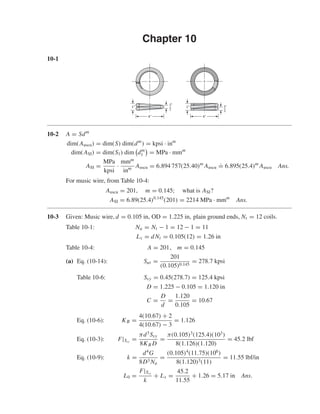
10-3 Given: Music wire, d = 0.105 in, OD = 1.225 in, plain ground ends, Nt = 12 coils.
Table 10-1: Na = Nt − 1 = 12 − 1 = 11
Ls = dNt = 0.105(12) = 1.26 in
Table 10-4: A = 201, m = 0.145
(a) Eq. (10-14): Sut =
201
(0.105)0.145
= 278.7 kpsi
Table 10-6: Ssy = 0.45(278.7) = 125.4 kpsi
D = 1.225 − 0.105 = 1.120 in
C =
D
d
=
1.120
0.105
= 10.67
Eq. (10-6): KB =
4(10.67) + 2
4(10.67) − 3
= 1.126
Eq. (10-3): F|Ssy
=
πd3
Ssy
8KB D
=
π(0.105)3
(125.4)(103
)
8(1.126)(1.120)
= 45.2 lbf
Eq. (10-9): k =
d4
G
8D3 Na
=
(0.105)4
(11.75)(106
)
8(1.120)3(11)
= 11.55 lbf/in
L0 =
F|Ssy
k
+ Ls =
45.2
11.55
+ 1.26 = 5.17 in Ans.
1
2
"
4"
1"
1
2
"
4"
1"
shi20396_ch10.qxd 8/11/03 4:39 PM Page 269
2. 270 Solutions Manual • Instructor’s Solution Manual to Accompany Mechanical Engineering Design
(b) F|Ssy
= 45.2 lbf Ans.
(c) k = 11.55 lbf/in Ans.
(d) (L0)cr =
2.63D
α
=
2.63(1.120)
0.5
= 5.89 in
Many designers provide (L0)cr/L0 ≥ 5 or more; therefore, plain ground ends are not
often used in machinery due to buckling uncertainty.
10-4 Referring to Prob. 10-3 solution, C = 10.67, Na = 11, Ssy = 125.4 kpsi, (L0)cr =
5.89 in and F = 45.2 lbf (at yield).
Eq. (10-18): 4 ≤ C ≤ 12 C = 10.67 O.K.
Eq. (10-19): 3 ≤ Na ≤ 15 Na = 11 O.K.
L0 = 5.17 in, Ls = 1.26 in
y1 =
F1
k
=
30
11.55
= 2.60 in
L1 = L0 − y1 = 5.17 − 2.60 = 2.57 in
ξ =
ys
y1
− 1 =
5.17 − 1.26
2.60
− 1 = 0.50
Eq. (10-20): ξ ≥ 0.15, ξ = 0.50 O.K.
From Eq. (10-3) for static service
τ1 = KB
8F1 D
πd3
= 1.126
8(30)(1.120)
π(0.105)3
= 83 224 psi
ns =
Ssy
τ1
=
125.4(103
)
83 224
= 1.51
Eq. (10-21): ns ≥ 1.2, ns = 1.51 O.K.
τs = τ1
45.2
30
= 83 224
45.2
30
= 125 391 psi
Ssy/τs = 125.4(103
)/125 391
.
= 1
Ssy/τs ≥ (ns)d: Not solid-safe. Not O.K.
L0 ≤ (L0)cr: 5.17 ≤ 5.89 Margin could be higher, Not O.K.
Design is unsatisfactory. Operate over a rod? Ans.
L0
L1
y1 F1
ys
Ls
Fs
shi20396_ch10.qxd 8/11/03 4:39 PM Page 270
3. Chapter 10 271
10-5 Static service spring with: HD steel wire, d = 2 mm, OD = 22 mm, Nt = 8.5 turns plain
and ground ends.
Preliminaries
Table 10-5: A = 1783 MPa · mmm
, m = 0.190
Eq. (10-14): Sut =
1783
(2)0.190
= 1563 MPa
Table 10-6: Ssy = 0.45(1563) = 703.4 MPa
Then,
D = OD − d = 22 − 2 = 20 mm
C = 20/2 = 10
KB =
4C + 2
4C − 3
=
4(10) + 2
4(10) − 3
= 1.135
Na = 8.5 − 1 = 7.5 turns
Ls = 2(8.5) = 17 mm
Eq. (10-21): Use (ns)d = 1.2 for solid-safe property.
Fs =
πd3
Ssy/nd
8KB D
=
π(2)3
(703.4/1.2)
8(1.135)(20)
(10−3
)3
(106
)
10−3
= 81.12 N
k =
d4
G
8D3 Na
=
(2)4
(79.3)
8(20)3(7.5)
(10−3
)4
(109
)
(10−3)3
= 0.002 643(106
) = 2643 N/m
ys =
Fs
k
=
81.12
2643(10−3)
= 30.69 mm
(a) L0 = y + Ls = 30.69 + 17 = 47.7 mm Ans.
(b) Table 10-1: p =
L0
Nt
=
47.7
8.5
= 5.61 mm Ans.
(c) Fs = 81.12 N (from above) Ans.
(d) k = 2643 N/m (from above) Ans.
(e) Table 10-2 and Eq. (10-13):
(L0)cr =
2.63D
α
=
2.63(20)
0.5
= 105.2 mm
(L0)cr/L0 = 105.2/47.7 = 2.21
This is less than 5. Operate over a rod?
Plain and ground ends have a poor eccentric footprint. Ans.
10-6 Referring to Prob. 10-5 solution: C = 10, Na = 7.5, k = 2643 N/m, d = 2 mm,
D = 20 mm, Fs = 81.12 N and Nt = 8.5 turns.
Eq. (10-18): 4 ≤ C ≤ 12, C = 10 O.K.
shi20396_ch10.qxd 8/11/03 4:39 PM Page 271
4. 272 Solutions Manual • Instructor’s Solution Manual to Accompany Mechanical Engineering Design
Eq. (10-19): 3 ≤ Na ≤ 15, Na = 7.5 O.K.
y1 =
F1
k
=
75
2643(10−3)
= 28.4 mm
(y)for yield =
81.12(1.2)
2643(10−3)
= 36.8 mm
ys =
81.12
2643(10−3)
= 30.69 mm
ξ =
(y)for yield
y1
− 1 =
36.8
28.4
− 1 = 0.296
Eq. (10-20): ξ ≥ 0.15, ξ = 0.296 O.K.
Table 10-6: Ssy = 0.45Sut O.K.
As-wound
τs = KB
8Fs D
πd3
= 1.135
8(81.12)(20)
π(2)3
10−3
(10−3)3(106)
= 586 MPa
Eq. (10-21):
Ssy
τs
=
703.4
586
= 1.2 O.K. (Basis for Prob. 10-5 solution)
Table 10-1: Ls = Ntd = 8.5(2) = 17 mm
L0 =
Fs
k
+ Ls =
81.12
2.643
+ 17 = 47.7 mm
2.63D
α
=
2.63(20)
0.5
= 105.2 mm
(L0)cr
L0
=
105.2
47.7
= 2.21
which is less than 5. Operate over a rod? Not O.K.
Plain and ground ends have a poor eccentric footprint. Ans.
10-7 Given: A228 (music wire), SQ&GRD ends, d = 0.006 in, OD = 0.036 in, L0 = 0.63 in,
Nt = 40 turns.
Table 10-4: A = 201 kpsi · inm
, m = 0.145
D = OD − d = 0.036 − 0.006 = 0.030 in
C = D/d = 0.030/0.006 = 5
KB =
4(5) + 2
4(5) − 3
= 1.294
Table 10-1: Na = Nt − 2 = 40 − 2 = 38 turns
Sut =
201
(0.006)0.145
= 422.1 kpsi
Ssy = 0.45(422.1) = 189.9 kpsi
k =
Gd4
8D3 Na
=
12(106
)(0.006)4
8(0.030)3(38)
= 1.895 lbf/in
shi20396_ch10.qxd 8/11/03 4:39 PM Page 272
5. Chapter 10 273
Table 10-1: Ls = Ntd = 40(0.006) = 0.240 in
Now Fs = kys where ys = L0 − Ls = 0.390 in. Thus,
τs = KB
8(kys)D
πd3
= 1.294
8(1.895)(0.39)(0.030)
π(0.006)3
(10−3
) = 338.2 kpsi (1)
τs > Ssy , that is, 338.2 > 189.9 kpsi; the spring is not solid-safe. Solving Eq. (1) for ys
gives
ys =
(τs/n)(πd3
)
8KBkD
=
(189 900/1.2)(π)(0.006)3
8(1.294)(1.895)(0.030)
= 0.182 in
Using a design factor of 1.2,
L0 = Ls + ys = 0.240 + 0.182 = 0.422 in
The spring should be wound to a free length of 0.422 in. Ans.
10-8 Given: B159 (phosphor bronze), SQ&GRD ends, d = 0.012 in, OD = 0.120 in, L0 =
0.81 in, Nt = 15.1 turns.
Table 10-4: A = 145 kpsi · inm
, m = 0
Table 10-5: G = 6 Mpsi
D = OD − d = 0.120 − 0.012 = 0.108 in
C = D/d = 0.108/0.012 = 9
KB =
4(9) + 2
4(9) − 3
= 1.152
Table 10-1: Na = Nt − 2 = 15.1 − 2 = 13.1 turns
Sut =
145
0.0120
= 145 kpsi
Table 10-6: Ssy = 0.35(145) = 50.8 kpsi
k =
Gd4
8D3 Na
=
6(106
)(0.012)4
8(0.108)3(13.1)
= 0.942 lbf/in
Table 10-1: Ls = dNt = 0.012(15.1) = 0.181 in
Now Fs = kys , ys = L0 − Ls = 0.81 − 0.181 = 0.629 in
τs = KB
8(kys)D
πd3
= 1.152
8(0.942)(0.6)(0.108)
π(0.012)3
(10−3
) = 108.6 kpsi (1)
τs > Ssy , that is,108.6 > 50.8 kpsi; the spring is not solid safe. Solving Eq. (1) for ys gives
ys =
(Ssy/n)πd3
8KBkD
=
(50.8/1.2)(π)(0.012)3
(103
)
8(1.152)(0.942)(0.108)
= 0.245 in
L0 = Ls + ys = 0.181 + 0.245 = 0.426 in
Wind the spring to a free length of 0.426 in. Ans.
shi20396_ch10.qxd 8/11/03 4:39 PM Page 273
6. 274 Solutions Manual • Instructor’s Solution Manual to Accompany Mechanical Engineering Design
10-9 Given: A313 (stainless steel), SQ&GRD ends, d = 0.040 in, OD = 0.240 in, L0 =
0.75 in, Nt = 10.4 turns.
Table 10-4: A = 169 kpsi · inm
, m = 0.146
Table 10-5: G = 10(106
) psi
D = OD − d = 0.240 − 0.040 = 0.200 in
C = D/d = 0.200/0.040 = 5
KB =
4(5) + 2
4(5) − 3
= 1.294
Table 10-6: Na = Nt − 2 = 10.4 − 2 = 8.4 turns
Sut =
169
(0.040)0.146
= 270.4 kpsi
Table 10-13: Ssy = 0.35(270.4) = 94.6 kpsi
k =
Gd4
8D3 Na
=
10(106
)(0.040)4
8(0.2)3(8.4)
= 47.62 lbf/in
Table 10-6: Ls = dNt = 0.040(10.4) = 0.416 in
Now Fs = kys , ys = L0 − Ls = 0.75 − 0.416 = 0.334 in
τs = KB
8(kys)D
πd3
= 1.294
8(47.62)(0.334)(0.2)
π(0.040)3
(10−3
) = 163.8 kpsi (1)
τs > Ssy , that is,163.8 > 94.6 kpsi; the spring is not solid-safe. Solving Eq. (1) for ys gives
ys =
(Ssy/n)(πd3
)
8KBkD
=
(94 600/1.2)(π)(0.040)3
8(1.294)(47.62)(0.2)
= 0.161 in
L0 = Ls + ys = 0.416 + 0.161 = 0.577 in
Wind the spring to a free length 0.577 in. Ans.
10-10 Given: A227 (hard drawn steel), d = 0.135 in, OD = 2.0 in, L0 = 2.94 in, Nt = 5.25
turns.
Table 10-4: A = 140 kpsi · inm
, m = 0.190
Table 10-5: G = 11.4(106
) psi
D = OD − d = 2 − 0.135 = 1.865 in
C = D/d = 1.865/0.135 = 13.81
KB =
4(13.81) + 2
4(13.81) − 3
= 1.096
Na = Nt − 2 = 5.25 − 2 = 3.25 turns
Sut =
140
(0.135)0.190
= 204.8 kpsi
shi20396_ch10.qxd 8/11/03 4:39 PM Page 274
7. Chapter 10 275
Table 10-6: Ssy = 0.45(204.8) = 92.2 kpsi
k =
Gd4
8D3 Na
=
11.4(106
)(0.135)4
8(1.865)3(3.25)
= 22.45 lbf/in
Table 10-1: Ls = dNt = 0.135(5.25) = 0.709 in
Now Fs = kys , ys = L0 − Ls = 2.94 − 0.709 = 2.231 in
τs = KB
8(kys)D
πd3
= 1.096
8(22.45)(2.231)(1.865)
π(0.135)3
(10−3
) = 106.0 kpsi (1)
τs > Ssy , that is,106 > 92.2 kpsi; the spring is not solid-safe. Solving Eq. (1) for ys gives
ys =
(Ssy/n)(πd3
)
8KBkD
=
(92 200/1.2)(π)(0.135)3
8(1.096)(22.45)(1.865)
= 1.612 in
L0 = Ls + ys = 0.709 + 1.612 = 2.321 in
Wind the spring to a free length of 2.32 in. Ans.
10-11 Given: A229 (OQ&T steel), SQ&GRD ends, d = 0.144 in, OD = 1.0 in, L0 = 3.75 in,
Nt = 13 turns.
Table 10-4: A = 147 kpsi · inm
, m = 0.187
Table 10-5: G = 11.4(106
) psi
D = OD − d = 1.0 − 0.144 = 0.856 in
C = D/d = 0.856/0.144 = 5.944
KB =
4(5.944) + 2
4(5.944) − 3
= 1.241
Table 10-1: Na = Nt − 2 = 13 − 2 = 11 turns
Sut =
147
(0.144)0.187
= 211.2 kpsi
Table 10-6: Ssy = 0.50(211.2) = 105.6 kpsi
k =
Gd4
8D3 Na
=
11.4(106
)(0.144)4
8(0.856)3(11)
= 88.8 lbf/in
Table 10-1: Ls = dNt = 0.144(13) = 1.872 in
Now Fs = kys, ys = L0 − Ls = 3.75 − 1.872 = 1.878 in
τs = KB
8(kys)D
πd3
= 1.241
8(88.8)(1.878)(0.856)
π(0.144)3
(10−3
) = 151.1 kpsi (1)
τs > Ssy , that is,151.1 > 105.6 kpsi; the spring is not solid-safe. Solving Eq. (1) for ys gives
ys =
(Ssy/n)(πd3
)
8KBkD
=
(105 600/1.2)(π)(0.144)3
8(1.241)(88.8)(0.856)
= 1.094 in
L0 = Ls + ys = 1.878 + 1.094 = 2.972 in
Wind the spring to a free length 2.972 in. Ans.
shi20396_ch10.qxd 8/11/03 4:39 PM Page 275
8. 276 Solutions Manual • Instructor’s Solution Manual to Accompany Mechanical Engineering Design
10-12 Given: A232 (Cr-V steel), SQ&GRD ends, d = 0.192 in, OD = 3 in, L0 = 9 in, Nt =
8 turns.
Table 10-4: A = 169 kpsi · inm
, m = 0.168
Table 10-5: G = 11.2(106
) psi
D = OD − d = 3 − 0.192 = 2.808 in
C = D/d = 2.808/0.192 = 14.625
KB =
4(14.625) + 2
4(14.625) − 3
= 1.090
Table 10-1: Na = Nt − 2 = 8 − 2 = 6 turns
Sut =
169
(0.192)0.168
= 223.0 kpsi
Table 10-6: Ssy = 0.50(223.0) = 111.5 kpsi
k =
Gd4
8D3 Na
=
11.2(106
)(0.192)4
8(2.808)3(6)
= 14.32 lbf/in
Table 10-1: Ls = dNt = 0.192(8) = 1.536 in
Now Fs = kys, ys = L0 − Ls = 9 − 1.536 = 7.464 in
τs = KB
8(kys)D
πd3
= 1.090
8(14.32)(7.464)(2.808)
π(0.192)3
(10−3
) = 117.7 kpsi (1)
τs > Ssy, that is,117.7 > 111.5 kpsi; the spring is not solid safe. Solving Eq. (1) for ys gives
ys =
(Ssy/n)(πd3
)
8KBkD
=
(111 500/1.2)(π)(0.192)3
8(1.090)(14.32)(2.808)
= 5.892 in
L0 = Ls + ys = 1.536 + 5.892 = 7.428 in
Wind the spring to a free length of 7.428 in. Ans.
10-13 Given: A313 (stainless steel) SQ&GRD ends, d = 0.2 mm, OD = 0.91 mm, L0 =
15.9 mm, Nt = 40 turns.
Table 10-4: A = 1867 MPa · mmm
, m = 0.146
Table 10-5: G = 69.0 GPa
D = OD − d = 0.91 − 0.2 = 0.71 mm
C = D/d = 0.71/0.2 = 3.55
KB =
4(3.55) + 2
4(3.55) − 3
= 1.446
Na = Nt − 2 = 40 − 2 = 38 turns
Sut =
1867
(0.2)0.146
= 2361.5 MPa
shi20396_ch10.qxd 8/11/03 4:39 PM Page 276
9. Chapter 10 277
Table 10-6:
Ssy = 0.35(2361.5) = 826.5 MPa
k =
d4
G
8D3 Na
=
(0.2)4
(69.0)
8(0.71)3(38)
(10−3
)4
(109
)
(10−3)3
= 1.0147(10−3
)(106
) = 1014.7 N/m or 1.0147 N/mm
Ls = dNt = 0.2(40) = 8 mm
Fs = kys
ys = L0 − Ls = 15.9 − 8 = 7.9
τs = KB
8(kys)D
πd3
= 1.446
8(1.0147)(7.9)(0.71)
π(0.2)3
10−3
(10−3
)(10−3
)
(10−3)3
= 2620(1) = 2620 MPa (1)
τs > Ssy , that is,2620 > 826.5 MPa; the spring is not solid safe. Solve Eq. (1) for ys giving
ys =
(Ssy/n)(πd3
)
8KBkD
=
(826.5/1.2)(π)(0.2)3
8(1.446)(1.0147)(0.71)
= 2.08 mm
L0 = Ls + ys = 8.0 + 2.08 = 10.08 mm
Wind the spring to a free length of 10.08 mm. This only addresses the solid-safe criteria.
There are additional problems. Ans.
10-14 Given: A228 (music wire), SQ&GRD ends, d = 1 mm, OD = 6.10 mm, L0 = 19.1 mm,
Nt = 10.4 turns.
Table 10-4: A = 2211 MPa · mmm
, m = 0.145
Table 10-5: G = 81.7 GPa
D = OD − d = 6.10 − 1 = 5.1 mm
C = D/d = 5.1/1 = 5.1
Na = Nt − 2 = 10.4 − 2 = 8.4 turns
KB =
4(5.1) + 2
4(5.1) − 3
= 1.287
Sut =
2211
(1)0.145
= 2211 MPa
Table 10-6: Ssy = 0.45(2211) = 995 MPa
k =
d4
G
8D3 Na
=
(1)4
(81.7)
8(5.1)3(8.4)
(10−3
)4
(109
)
(10−3)3
= 0.009 165(106
)
= 9165 N/m or 9.165 N/mm
Ls = dNt = 1(10.4) = 10.4 mm
Fs = kys
shi20396_ch10.qxd 8/11/03 4:39 PM Page 277
10. 278 Solutions Manual • Instructor’s Solution Manual to Accompany Mechanical Engineering Design
ys = L0 − Ls = 19.1 − 10.4 = 8.7 mm
τs = KB
8(kys)D
πd3
= 1.287
8(9.165)(8.7)(5.1)
π(1)3
= 1333 MPa (1)
τs > Ssy , that is, 1333 > 995 MPa; the spring is not solid safe. Solve Eq. (1) for ys giving
ys =
(Ssy/n)(πd3
)
8KBkD
=
(995/1.2)(π)(1)3
8(1.287)(9.165)(5.1)
= 5.43 mm
L0 = Ls + ys = 10.4 + 5.43 = 15.83 mm
Wind the spring to a free length of 15.83 mm. Ans.
10-15 Given: A229 (OQ&T spring steel), SQ&GRD ends, d = 3.4 mm, OD = 50.8 mm, L0 =
74.6 mm, Nt = 5.25.
Table 10-4: A = 1855 MPa · mmm
, m = 0.187
Table 10-5: G = 77.2 GPa
D = OD − d = 50.8 − 3.4 = 47.4 mm
C = D/d = 47.4/3.4 = 13.94
Na = Nt − 2 = 5.25 − 2 = 3.25 turns
KB =
4(13.94) + 2
4(13.94) − 3
= 1.095
Sut =
1855
(3.4)0.187
= 1476 MPa
Table 10-6: Ssy = 0.50(1476) = 737.8 MPa
k =
d4
G
8D3 Na
=
(3.4)4
(77.2)
8(47.4)3(3.25)
(10−3
)4
(109
)
(10−3)3
= 0.003 75(106
)
= 3750 N/m or 3.750 N/mm
Ls = dNt = 3.4(5.25) = 17.85
Fs = kys
ys = L0 − Ls = 74.6 − 17.85 = 56.75 mm
τs = KB
8(kys)D
πd3
= 1.095
8(3.750)(56.75)(47.4)
π(3.4)3
= 720.2 MPa (1)
τs < Ssy , that is, 720.2 < 737.8 MPa
shi20396_ch10.qxd 8/11/03 4:39 PM Page 278
11. Chapter 10 279
∴ The spring is solid safe. With ns = 1.2,
ys =
(Ssy/n)(πd3
)
8KBkD
=
(737.8/1.2)(π)(3.4)3
8(1.095)(3.75)(47.4)
= 48.76 mm
L0 = Ls + ys = 17.85 + 48.76 = 66.61 mm
Wind the spring to a free length of 66.61 mm. Ans.
10-16 Given: B159 (phosphor bronze), SQ&GRD ends, d = 3.7 mm, OD = 25.4 mm, L0 =
95.3 mm, Nt = 13 turns.
Table 10-4: A = 932 MPa · mmm
, m = 0.064
Table 10-5: G = 41.4 GPa
D = OD − d = 25.4 − 3.7 = 21.7 mm
C = D/d = 21.7/3.7 = 5.865
KB =
4(5.865) + 2
4(5.865) − 3
= 1.244
Na = Nt − 2 = 13 − 2 = 11 turns
Sut =
932
(3.7)0.064
= 857.1 MPa
Table 10-6: Ssy = 0.35(857.1) = 300 MPa
k =
d4
G
8D3 Na
=
(3.7)4
(41.4)
8(21.7)3(11)
(10−3
)4
(109
)
(10−3)3
= 0.008 629(106
)
= 8629 N/m or 8.629 N/mm
Ls = dNt = 3.7(13) = 48.1 mm
Fs = kys
ys = L0 − Ls = 95.3 − 48.1 = 47.2 mm
τs = KB
8(kys)D
πd3
= 1.244
8(8.629)(47.2)(21.7)
π(3.7)3
= 553 MPa (1)
τs > Ssy , that is,553 > 300 MPa; the spring is not solid-safe. Solving Eq. (1) for ys gives
ys =
(Ssy/n)(πd3
)
8KBkD
=
(300/1.2)(π)(3.7)3
8(1.244)(8.629)(21.7)
= 21.35 mm
L0 = Ls + ys = 48.1 + 21.35 = 69.45 mm
Wind the spring to a free length of 69.45 mm. Ans.
shi20396_ch10.qxd 8/11/03 4:40 PM Page 279
12. 280 Solutions Manual • Instructor’s Solution Manual to Accompany Mechanical Engineering Design
10-17 Given: A232 (Cr-V steel), SQ&GRD ends, d = 4.3 mm, OD = 76.2 mm, L0 =
228.6 mm, Nt = 8 turns.
Table 10-4: A = 2005 MPa · mmm
, m = 0.168
Table 10-5: G = 77.2 GPa
D = OD − d = 76.2 − 4.3 = 71.9 mm
C = D/d = 71.9/4.3 = 16.72
KB =
4(16.72) + 2
4(16.72) − 3
= 1.078
Na = Nt − 2 = 8 − 2 = 6 turns
Sut =
2005
(4.3)0.168
= 1569 MPa
Table 10-6:
Ssy = 0.50(1569) = 784.5 MPa
k =
d4
G
8D3 Na
=
(4.3)4
(77.2)
8(71.9)3(6)
(10−3
)4
(109
)
(10−3)3
= 0.001 479(106
)
= 1479 N/m or 1.479 N/mm
Ls = dNt = 4.3(8) = 34.4 mm
Fs = kys
ys = L0 − Ls = 228.6 − 34.4 = 194.2 mm
τs = KB
8(kys)D
πd3
= 1.078
8(1.479)(194.2)(71.9)
π(4.3)3
= 713.0 MPa (1)
τs < Ssy, that is, 713.0 < 784.5; the spring is solid safe. With ns = 1.2
Eq. (1) becomes
ys =
(Ssy/n)(πd3
)
8KBkD
=
(784.5/1.2)(π)(4.3)3
8(1.078)(1.479)(71.9)
= 178.1 mm
L0 = Ls + ys = 34.4 + 178.1 = 212.5 mm
Wind the spring to a free length of L0 = 212.5 mm. Ans.
10-18 For the wire diameter analyzed, G = 11.75 Mpsi per Table 10-5. Use squared and ground
ends. The following is a spread-sheet study using Fig. 10-3 for parts (a) and (b). For Na,
k = 20/2 = 10 lbf/in.
shi20396_ch10.qxd 8/11/03 4:40 PM Page 280
13. Chapter 10 281
(a) Spring over a Rod (b) Spring in a Hole
Source Parameter Values Source Parameter Values
d 0.075 0.08 0.085 d 0.075 0.08 0.085
D 0.875 0.88 0.885 D 0.875 0.870 0.865
ID 0.800 0.800 0.800 ID 0.800 0.790 0.780
OD 0.950 0.960 0.970 OD 0.950 0.950 0.950
Eq. (10-2) C 11.667 11.000 10.412 Eq. (10-2) C 11.667 10.875 10.176
Eq. (10-9) Na 6.937 8.828 11.061 Eq. (10-9) Na 6.937 9.136 11.846
Table 10-1 Nt 8.937 10.828 13.061 Table 10-1 Nt 8.937 11.136 13.846
Table 10-1 Ls 0.670 0.866 1.110 Table 10-1 Ls 0.670 0.891 1.177
1.15y + Ls L0 2.970 3.166 3.410 1.15y + Ls L0 2.970 3.191 3.477
Eq. (10-13) (L0)cr 4.603 4.629 4.655 Eq. (10-13) (L0)cr 4.603 4.576 4.550
Table 10-4 A 201.000 201.000 201.000 Table 10-4 A 201.000 201.000 201.000
Table 10-4 m 0.145 0.145 0.145 Table 10-4 m 0.145 0.145 0.145
Eq. (10-14) Sut 292.626 289.900 287.363 Eq. (10-14) Sut 292.626 289.900 287.363
Table 10-6 Ssy 131.681 130.455 129.313 Table 10-6 Ssy 131.681 130.455 129.313
Eq. (10-6) KB 1.115 1.122 1.129 Eq. (10-6) KB 1.115 1.123 1.133
Eq. (10-3) n 0.973 1.155 1.357 Eq. (10-3) n 0.973 1.167 1.384
Eq. (10-22) fom −0.282 −0.391 −0.536 Eq. (10-22) fom −0.282 −0.398 −0.555
For ns ≥ 1.2, the optimal size is d = 0.085 in for both cases.
10-19 From the figure: L0 = 120 mm, OD = 50 mm, and d = 3.4 mm. Thus
D = OD − d = 50 − 3.4 = 46.6 mm
(a) By counting, Nt = 12.5 turns. Since the ends are squared along1/4 turn on each end,
Na = 12.5 − 0.5 = 12 turns Ans.
p = 120/12 = 10 mm Ans.
The solid stack is 13 diameters across the top and 12 across the bottom.
Ls = 13(3.4) = 44.2 mm Ans.
(b) d = 3.4/25.4 = 0.1339 in and from Table 10-5, G = 78.6 GPa
k =
d4
G
8D3 Na
=
(3.4)4
(78.6)(109
)
8(46.6)3(12)
(10−3
) = 1080 N/m Ans.
(c) Fs = k(L0 − Ls) = 1080(120 − 44.2)(10−3
) = 81.9 N Ans.
(d) C = D/d = 46.6/3.4 = 13.71
KB =
4(13.71) + 2
4(13.71) − 3
= 1.096
τs =
8KB Fs D
πd3
=
8(1.096)(81.9)(46.6)
π(3.4)3
= 271 MPa Ans.
10-20 One approach is to select A227-47 HD steel for its low cost. Then, for y1 ≤ 3/8 at
F1 = 10 lbf, k ≥10/0.375 = 26.67 lbf/in. Try d = 0.080 in #14 gauge
shi20396_ch10.qxd 8/11/03 4:40 PM Page 281
14. 282 Solutions Manual • Instructor’s Solution Manual to Accompany Mechanical Engineering Design
For a clearance of 0.05 in: ID = (7/16) + 0.05 = 0.4875 in; OD = 0.4875 + 0.16 =
0.6475 in
D = 0.4875 + 0.080 = 0.5675 in
C = 0.5675/0.08 = 7.094
G = 11.5 Mpsi
Na =
d4
G
8kD3
=
(0.08)4
(11.5)(106
)
8(26.67)(0.5675)3
= 12.0 turns
Nt = 12 + 2 = 14 turns, Ls = dNt = 0.08(14) = 1.12 in O.K.
L0 = 1.875 in, ys = 1.875 − 1.12 = 0.755 in
Fs = kys = 26.67(0.755) = 20.14 lbf
KB =
4(7.094) + 2
4(7.094) − 3
= 1.197
τs = KB
8Fs D
πd3
= 1.197
8(20.14)(0.5675)
π(0.08)3
= 68 046 psi
Table 10-4: A = 140 kpsi · inm
, m = 0.190
Ssy = 0.45
140
(0.080)0.190
= 101.8 kpsi
n =
101.8
68.05
= 1.50 > 1.2 O.K.
τ1 =
F1
Fs
τs =
10
20.14
(68.05) = 33.79 kpsi,
n1 =
101.8
33.79
= 3.01 > 1.5 O.K.
There is much latitude for reducing the amount of material. Iterate on y1 using a spread
sheet. The final results are: y1 = 0.32 in, k = 31.25 lbf/in, Na = 10.3 turns, Nt =
12.3 turns, Ls = 0.985 in, L0 = 1.820 in, ys = 0.835 in, Fs = 26.1 lbf, KB = 1.197,
τs = 88 190 kpsi, ns = 1.15, and n1 = 3.01.
ID = 0.4875 in, OD = 0.6475 in, d = 0.080 in
Try other sizes and/or materials.
10-21 A stock spring catalog may have over two hundred pages of compression springs with up
to 80 springs per page listed.
• Students should be aware that such catalogs exist.
• Many springs are selected from catalogs rather than designed.
• The wire size you want may not be listed.
• Catalogs may also be available on disk or the web through search routines. For exam-
ple, disks are available from Century Spring at
1 − (800) − 237 − 5225
www.centuryspring.com
• It is better to familiarize yourself with vendor resources rather than invent them yourself.
• Sample catalog pages can be given to students for study.
shi20396_ch10.qxd 8/11/03 4:40 PM Page 282
15. Chapter 10 283
10-22 For a coil radius given by:
R = R1 +
R2 − R1
2π N
θ
The torsion of a section is T = P R where dL = R dθ
δp =
∂U
∂ P
=
1
G J
T
∂T
∂ P
dL =
1
G J
2π N
0
P R3
dθ
=
P
G J
2π N
0
R1 +
R2 − R1
2π N
θ
3
dθ
=
P
G J
1
4
2π N
R2 − R1
R1 +
R2 − R1
2π N
θ
4 2π N
0
=
π PN
2G J(R2 − R1)
R4
2 − R4
1 =
π PN
2G J
(R1 + R2) R2
1 + R2
2
J =
π
32
d4
∴ δp =
16PN
Gd4
(R1 + R2) R2
1 + R2
2
k =
P
δp
=
d4
G
16N(R1 + R2) R2
1 + R2
2
Ans.
10-23 For a food service machinery application select A313 Stainless wire.
G = 10(106
) psi
Note that for 0.013 ≤ d ≤ 0.10 in A = 169, m = 0.146
0.10 < d ≤ 0.20 in A = 128, m = 0.263
Fa =
18 − 4
2
= 7 lbf, Fm =
18 + 4
2
= 11 lbf, r = 7/11
k = F/ y =
18 − 4
2.5 − 1
= 9.333 lbf/in
Try d = 0.080 in, Sut =
169
(0.08)0.146
= 244.4 kpsi
Ssu = 0.67Sut = 163.7 kpsi, Ssy = 0.35Sut = 85.5 kpsi
Try unpeened using Zimmerli’s endurance data: Ssa = 35 kpsi, Ssm = 55 kpsi
Gerber: Sse =
Ssa
1 − (Ssm/Ssu)2
=
35
1 − (55/163.7)2
= 39.5 kpsi
Ssa =
(7/11)2
(163.7)2
2(39.5)
−1 + 1 +
2(39.5)
(7/11)(163.7)
2
= 35.0 kpsi
α = Ssa/nf = 35.0/1.5 = 23.3 kpsi
β =
8Fa
πd2
(10−3
) =
8(7)
π(0.082)
(10−3
) = 2.785 kpsi
C =
2(23.3) − 2.785
4(2.785)
+
2(23.3) − 2.785
4(2.785)
2
−
3(23.3)
4(2.785)
= 6.97
D = Cd = 6.97(0.08) = 0.558 in
shi20396_ch10.qxd 8/11/03 4:40 PM Page 283
16. 284 Solutions Manual • Instructor’s Solution Manual to Accompany Mechanical Engineering Design
KB =
4(6.97) + 2
4(6.97) − 3
= 1.201
τa = KB
8Fa D
πd3
= 1.201
8(7)(0.558)
π(0.083)
(10−3
) = 23.3 kpsi
nf = 35/23.3 = 1.50 checks
Na =
Gd4
8kD3
=
10(106
)(0.08)4
8(9.333)(0.558)3
= 31.58 turns
Nt = 31.58 + 2 = 33.58 turns, Ls = dNt = 0.08(33.58) = 2.686 in
ys = (1 + ξ)ymax = (1 + 0.15)(2.5) = 2.875 in
L0 = 2.686 + 2.875 = 5.561 in
(L0)cr = 2.63
D
α
=
2.63(0.558)
0.5
= 2.935 in
τs = 1.15(18/7)τa = 1.15(18/7)(23.3) = 68.9 kpsi
ns = Ssy/τs = 85.5/68.9 = 1.24
f =
kg
π2d2 DNaγ
=
9.333(386)
π2(0.082)(0.558)(31.58)(0.283)
= 107 Hz
These steps are easily implemented on a spreadsheet, as shown below, for different
diameters.
d1 d2 d3 d4
d 0.080 0.0915 0.1055 0.1205
m 0.146 0.146 0.263 0.263
A 169.000 169.000 128.000 128.000
Sut 244.363 239.618 231.257 223.311
Ssu 163.723 160.544 154.942 149.618
Ssy 85.527 83.866 80.940 78.159
Sse 39.452 39.654 40.046 40.469
Ssa 35.000 35.000 35.000 35.000
α 23.333 23.333 23.333 23.333
β 2.785 2.129 1.602 1.228
C 6.977 9.603 13.244 17.702
D 0.558 0.879 1.397 2.133
KB 1.201 1.141 1.100 1.074
τa 23.333 23.333 23.333 23.333
nf 1.500 1.500 1.500 1.500
Na 31.547 13.836 6.082 2.910
Nt 33.547 15.836 8.082 4.910
Ls 2.684 1.449 0.853 0.592
ymax 2.875 2.875 2.875 2.875
L0 5.559 4.324 3.728 3.467
(L0)cr 2.936 4.622 7.350 11.220
τs 69.000 69.000 69.000 69.000
ns 1.240 1.215 1.173 1.133
f (Hz) 106.985 112.568 116.778 119.639
shi20396_ch10.qxd 8/11/03 4:40 PM Page 284
17. Chapter 10 285
The shaded areas depict conditions outside the recommended design conditions. Thus,
one spring is satisfactory–A313, as wound, unpeened, squared and ground,
d = 0.0915 in, OD = 0.879 + 0.092 = 0.971 in, Nt = 15.84 turns
10-24 The steps are the same as in Prob. 10-23 except that the Gerber-Zimmerli criterion is
replaced with Goodman-Zimmerli:
Sse =
Ssa
1 − (Ssm/Ssu)
The problem then proceeds as in Prob. 10-23. The results for the wire sizes are shown
below (see solution to Prob. 10-23 for additional details).
Iteration of d for the first trial
d1 d2 d3 d4 d1 d2 d3 d4
d 0.080 0.0915 0.1055 0.1205 d 0.080 0.0915 0.1055 0.1205
m 0.146 0.146 0.263 0.263 KB 1.151 1.108 1.078 1.058
A 169.000 169.000 128.000 128.000 τa 29.008 29.040 29.090 29.127
Sut 244.363 239.618 231.257 223.311 nf 1.500 1.500 1.500 1.500
Ssu 163.723 160.544 154.942 149.618 Na 14.444 6.572 2.951 1.429
Ssy 85.527 83.866 80.940 78.159 Nt 16.444 8.572 4.951 3.429
Sse 52.706 53.239 54.261 55.345 Ls 1.316 0.784 0.522 0.413
Ssa 43.513 43.560 43.634 43.691 ymax 2.875 2.875 2.875 2.875
α 29.008 29.040 29.090 29.127 L0 4.191 3.659 3.397 3.288
β 2.785 2.129 1.602 1.228 (L0)cr 3.809 5.924 9.354 14.219
C 9.052 12.309 16.856 22.433 τs 85.782 85.876 86.022 86.133
D 0.724 1.126 1.778 2.703 ns 0.997 0.977 0.941 0.907
f (Hz) 138.806 144.277 148.617 151.618
Without checking all of the design conditions, it is obvious that none of the wire sizes
satisfyns ≥ 1.2.Also, the Gerber line is closer to the yield line than the Goodman. Setting
nf = 1.5 for Goodman makes it impossible to reach the yield line (ns < 1). The table
below uses nf = 2.
Iteration of d for the second trial
d1 d2 d3 d4 d1 d2 d3 d4
d 0.080 0.0915 0.1055 0.1205 d 0.080 0.0915 0.1055 0.1205
m 0.146 0.146 0.263 0.263 KB 1.221 1.154 1.108 1.079
A 169.000 169.000 128.000 128.000 τa 21.756 21.780 21.817 21.845
Sut 244.363 239.618 231.257 223.311 nf 2.000 2.000 2.000 2.000
Ssu 163.723 160.544 154.942 149.618 Na 40.962 17.594 7.609 3.602
Ssy 85.527 83.866 80.940 78.159 Nt 42.962 19.594 9.609 5.602
Sse 52.706 53.239 54.261 55.345 Ls 3.437 1.793 1.014 0.675
Ssa 43.513 43.560 43.634 43.691 ymax 2.875 2.875 2.875 2.875
α 21.756 21.780 21.817 21.845 L0 6.312 4.668 3.889 3.550
β 2.785 2.129 1.602 1.228 (L0)cr 2.691 4.266 6.821 10.449
C 6.395 8.864 12.292 16.485 τs 64.336 64.407 64.517 64.600
D 0.512 0.811 1.297 1.986 ns 1.329 1.302 1.255 1.210
f (Hz) 98.065 103.903 108.376 111.418
The satisfactory spring has design specifications of: A313, as wound, unpeened, squared
and ground, d = 0.0915 in, OD = 0.811 + 0.092 = 0.903 in, Nt = 19.6 turns.
shi20396_ch10.qxd 8/11/03 4:40 PM Page 285
18. 286 Solutions Manual • Instructor’s Solution Manual to Accompany Mechanical Engineering Design
10-25 This is the same as Prob. 10-23 since Sse = Ssa = 35 kpsi. Therefore, design the spring
using: A313, as wound, un-peened, squared and ground, d = 0.915 in, OD = 0.971 in,
Nt = 15.84 turns.
10-26 For the Gerber fatigue-failure criterion, Ssu = 0.67Sut,
Sse =
Ssa
1 − (Ssm/Ssu)2
, Ssa =
r2
S2
su
2Sse
−1 + 1 +
2Sse
rSsu
2
The equation for Ssa is the basic difference. The last 2 columns of diameters of Ex. 10-5
are presented below with additional calculations.
d = 0.105 d = 0.112 d = 0.105 d = 0.112
Sut 278.691 276.096 Na 8.915 6.190
Ssu 186.723 184.984 Ls 1.146 0.917
Sse 38.325 38.394 L0 3.446 3.217
Ssy 125.411 124.243 (L0)cr 6.630 8.160
Ssa 34.658 34.652 KB 1.111 1.095
α 23.105 23.101 τa 23.105 23.101
β 1.732 1.523 nf 1.500 1.500
C 12.004 13.851 τs 70.855 70.844
D 1.260 1.551 ns 1.770 1.754
ID 1.155 1.439 fn 105.433 106.922
OD 1.365 1.663 fom −0.973 −1.022
There are only slight changes in the results.
10-27 As in Prob. 10-26, the basic change is Ssa.
For Goodman, Sse =
Ssa
1 − (Ssm/Ssu)
Recalculate Ssa with
Ssa =
rSseSsu
rSsu + Sse
Calculations for the last 2 diameters of Ex. 10-5 are given below.
d = 0.105 d = 0.112 d = 0.105 d = 0.112
Sut 278.691 276.096 Na 9.153 6.353
Ssu 186.723 184.984 Ls 1.171 0.936
Sse 49.614 49.810 L0 3.471 3.236
Ssy 125.411 124.243 (L0)cr 6.572 8.090
Ssa 34.386 34.380 KB 1.112 1.096
α 22.924 22.920 τa 22.924 22.920
β 1.732 1.523 nf 1.500 1.500
C 11.899 13.732 τs 70.301 70.289
D 1.249 1.538 ns 1.784 1.768
ID 1.144 1.426 fn 104.509 106.000
OD 1.354 1.650 fom −0.986 −1.034
There are only slight differences in the results.
shi20396_ch10.qxd 8/11/03 4:40 PM Page 286
19. Chapter 10 287
10-28 Use: E = 28.6 Mpsi, G = 11.5 Mpsi, A = 140 kpsi · inm
, m = 0.190, rel cost = 1.
Try d = 0.067 in, Sut =
140
(0.067)0.190
= 234.0 kpsi
Table 10-6: Ssy = 0.45Sut = 105.3 kpsi
Table 10-7: Sy = 0.75Sut = 175.5 kpsi
Eq. (10-34) with D/d = C and C1 = C
σA =
Fmax
πd2
[(K)A(16C) + 4] =
Sy
ny
4C2
− C − 1
4C(C − 1)
(16C) + 4 =
πd2
Sy
ny Fmax
4C2
− C − 1 = (C − 1)
πd2
Sy
4ny Fmax
− 1
C2
−
1
4
1 +
πd2
Sy
4ny Fmax
− 1 C +
1
4
πd2
Sy
4ny Fmax
− 2 = 0
C =
1
2
πd2
Sy
16ny Fmax
±
πd2Sy
16ny Fmax
2
−
πd2Sy
4ny Fmax
+ 2
=
1
2
π(0.0672
)(175.5)(103
)
16(1.5)(18)
+
π(0.067)2(175.5)(103)
16(1.5)(18)
2
−
π(0.067)2(175.5)(103)
4(1.5)(18)
+ 2
= 4.590
D = Cd = 0.3075 in
Fi =
πd3
τi
8D
=
πd3
8D
33 500
exp(0.105C)
± 1000 4 −
C − 3
6.5
Use the lowest Fi in the preferred range. This results in the best fom.
Fi =
π(0.067)3
8(0.3075)
33 500
exp[0.105(4.590)]
− 1000 4 −
4.590 − 3
6.5
= 6.505 lbf
For simplicity, we will round up to the next integer or half integer;
therefore, use Fi = 7 lbf
k =
18 − 7
0.5
= 22 lbf/in
Na =
d4
G
8kD3
=
(0.067)4
(11.5)(106
)
8(22)(0.3075)3
= 45.28 turns
Nb = Na −
G
E
= 45.28 −
11.5
28.6
= 44.88 turns
L0 = (2C − 1 + Nb)d = [2(4.590) − 1 + 44.88](0.067) = 3.555 in
L18 lbf = 3.555 + 0.5 = 4.055 in
take positive root
shi20396_ch10.qxd 8/11/03 4:40 PM Page 287
26. 294 Solutions Manual • Instructor’s Solution Manual to Accompany Mechanical Engineering Design
10-31 For the hook,
M = F R sin θ, ∂M/∂F = R sin θ
δF =
1
E I
π/2
0
F R2
sin2
R dθ =
π
2
P R3
E I
The total deflection of the body and the two hooks
δ =
8FD3
Nb
d4G
+ 2
π
2
F R3
E I
=
8FD3
Nb
d4G
+
π F(D/2)3
E(π/64)(d4)
=
8FD3
d4G
Nb +
G
E
=
8FD3
Na
d4G
І Na = Nb +
G
E
QED
10-32 Table 10-4 for A227:
A = 140 kpsi · inm
, m = 0.190
Table 10-5: E = 28.5(106
) psi
Sut =
140
(0.162)0.190
= 197.8 kpsi
Eq. (10-57):
Sy = σall = 0.78(197.8) = 154.3 kpsi
D = 1.25 − 0.162 = 1.088 in
C = D/d = 1.088/0.162 = 6.72
Ki =
4C2
− C − 1
4C(C − 1)
=
4(6.72)2
− 6.72 − 1
4(6.72)(6.72 − 1)
= 1.125
From σ = Ki
32M
πd3
Solving for M for the yield condition,
My =
πd3
Sy
32Ki
=
π(0.162)3
(154 300)
32(1.125)
= 57.2 lbf · in
Count the turns when M = 0
N = 2.5 −
My
d4 E/(10.8DN)
from which
N =
2.5
1 + [10.8DMy/(d4 E)]
=
2.5
1 + {[10.8(1.088)(57.2)]/[(0.162)4(28.5)(106)]}
= 2.417 turns
F
R ϭ D͞2
shi20396_ch10.qxd 8/11/03 4:40 PM Page 294
27. Chapter 10 295
This means (2.5 − 2.417)(360◦
) or 29.9◦
from closed. Treating the hand force as in the
middle of the grip
r = 1 +
3.5
2
= 2.75 in
F =
My
r
=
57.2
2.75
= 20.8 lbf Ans.
10-33 The spring material and condition are unknown. Given d = 0.081 in and OD = 0.500,
(a) D = 0.500 − 0.081 = 0.419 in
Using E = 28.6 Mpsi for an estimate
k =
d4
E
10.8DN
=
(0.081)4
(28.6)(106
)
10.8(0.419)(11)
= 24.7 lbf · in/turn
for each spring. The moment corresponding to a force of 8 lbf
Fr = (8/2)(3.3125) = 13.25 lbf · in/spring
The fraction windup turn is
n =
Fr
k
=
13.25
24.7
= 0.536 turns
The arm swings through an arc of slightly less than 180◦
, say 165◦
. This uses up
165/360 or 0.458 turns. So n = 0.536 − 0.458 = 0.078 turns are left (or
0.078(360◦
) = 28.1◦
). The original configuration of the spring was
Ans.
(b)
C =
0.419
0.081
= 5.17
Ki =
4(5.17)2
− 5.17 − 1
4(5.17)(5.17 − 1)
= 1.168
σ = Ki
32M
πd3
= 1.168
32(13.25)
π(0.081)3
= 296 623 psi Ans.
To achieve this stress level, the spring had to have set removed.
10-34 Consider half and double results
Straight section: M = 3F R,
∂M
∂ P
= 3RF
3FR
L͞2
28.1Њ
shi20396_ch10.qxd 8/11/03 4:40 PM Page 295
28. 296 Solutions Manual • Instructor’s Solution Manual to Accompany Mechanical Engineering Design
Upper 180◦
section:
M = F[R + R(1 − cos φ)]
= F R(2 − cos φ),
∂M
∂ P
= R(2 − cos φ)
Lower section: M = F R sin θ
∂M
∂ P
= R sin θ
Considering bending only:
δ =
2
E I
L/2
0
9F R2
dx +
π
0
F R2
(2 − cos φ)2
R dφ +
π/2
0
F(R sin θ)2
R dθ
=
2F
E I
9
2
R2
L + R3
4π − 4 sin φ
π
0
+
π
2
+ R3 π
4
=
2F R2
E I
19π
4
R +
9
2
L =
F R2
2E I
(19π R + 18L) Ans.
10-35 Computer programs will vary.
10-36 Computer programs will vary.
F
R
shi20396_ch10.qxd 8/11/03 4:40 PM Page 296