2. Fluoroscopic Imaging
The primary function of a fluoroscope is to perform dynamic studies - used to
visualize the motion of internal structures and fluids.
Fluoroscopy differs from most other X-ray imaging and the purpose of this
technique is to get real-time and moving images of the organs inside a
person, allowing evaluation of dynamic, biological processes and guiding
interventions.
Early fluoroscopes had an X-ray source and a fluorescent screen, between which
the patient was placed. After passing through the patient, the remnant beam
impinged upon the fluorescent screen and produced a visible glow, which was
directly observed by the practitioner.
3. Fluoroscopist need not stand in close proximity to the fluorescent screen in
order to observe the live image and results in a substantial reduction in
radiation dose to the fluoroscopist
In modern systems, the fluorescent screen is coupled to an electronic device
that amplifies and transforms the glowing light into a video signal suitable for
presentation on an electronic display.
Patients receive less radiation dose as well, because of the amplification and
overall efficiency of the imaging system.
5. ➢
The X-ray image intensifier is an electronic device that converts the X-ray beam
intensity pattern into a visible image suitable for capture by a video camera and
displayed on a video display monitor.
X RAY IMAGE INTENSIFIER - XRII
7. Glass envelope
Maintains tube vacuum to allow control of e-flow, has no functional part in image
formation.
Input phosphor
X-Rays that exit the patient and are incident on the image intensifier tube are
transmitted through the glass envelope and interact with the input phosphor, which is
cesium iodide.
When X-Rays interact with the input phosphor,
its energy is converted into a burst of visible light
photons as occurs on the intensifying screen.
9. Photocathode
It is bonded directly to the input phosphor
with a thin, transparent, adhesive layer.
The photocathode is a thin metal layer,
composed of cesium and antimony compounds, that
respond to stimulation by light with the emission of
electrons.
This process is known as photoemission or photoelectric
effect
10. Located along the length of the tube, responsible
for focusing the electrons across the tube from
the input to the output phosphor.
The image is reversed from input to the output phosphor
(right becomes left, superior to inferior).
The concave input screen reduces distortion by keeping
the same distance between all points on the input &
output screens.
Electrostatic Focusing Lenses
11. ANODE
An anode is normally charged with 25 kV and is used to accelerate electrons across the
tube to increase kinetic energy and to increase light energy too.
.
OUTPUT PHOSPHOR
The output Phosphor is
normally made of Zinc
Cadmium Sulfide crystals.
Each photoelectron reaches the
output phosphor results in
approximately 50 -70 more
than the input.
The electrons that are steered, accelerated, and multiplied in number by the electron
optic components, and finally impinge upon a surface coated with a phosphor material
that glows visibly when struck by high-energy electrons. This is the output phosphor of
the XRII.
12. The XRII achieves orders of magnitude more light per X-ray photon than a
simple fluorescent screen.
This occurs through electronic gain (amplification by the electron optics) and
minification gain (concentrating the information from a large input surface area
to a small output phosphor area.
This allows relatively high image quality (signal-to-noise ratio) at modest dose
levels compared with non-intensified fluoroscopy.
The use of video technology added an important convenience factor — it allows
several people to observe the image simultaneously and offers the ability to
record and post-process fluoroscopic image sequences.
13. The two methods commonly used to couple the television camera tube to the
image-intensifier tube are
1. Fiber optics
2. Lens system
The simplest method is to use a bundle of fiber optics
14. The output screen image can be transferred to different optical displaying
systems:
Conventional TV
Cine film
Photography
Viewing and Recording of Images
Two methods are used to electronically convert the visible image on the
output phosphor of the image intensifier into an electronic signal.
1. Thermionic television camera tube
2. The solid-state charge-coupled device (CCD)
15. Types of TV Camera
VIDICON TV camera
improvement of contrast
improvement of signal-to-noise ratio
high image lag
PLUMBICON TV camera (suitable for cardiology)
lower image lag (follow-up of organ motion)
higher quantum noise level
CCD TV camera (Digital fluoroscopy)
digital fluoroscopy spot films are limited in resolution since they
depend on the TV camera (no better than about 2 c/mm) for a
1000-line TV system.
16. Older fluoroscopy equipment will have a television system using a camera tube.
The camera tube has a glass envelope containing a thin conductive layer coated
onto the inside surface of the glass envelope.
The television camera consists of cylindrical housing, approximately 15 mm in
diameter by 25 cm in length, that contains the heart of the camera, the TV
camera tube.
It also contains electromagnetic coils that are used to properly steer the
electron beam inside the tube
Vidicon and Plumbicon are used most often
18. 18
Direct Fluoroscopy: obsolete
In older fluoroscopic examinations radiologist stands behind the screen and
views the picture.
Radiologist receives high exposure; despite protective glass, lead shielding in the
stand, apron, and perhaps goggles.
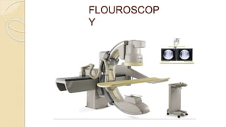
20. Different Fluoroscopy Systems
Remote control systems
◦ Not requiring the presence of medical
specialists inside the X-Ray room
Mobile C-arms
◦ Mostly used in surgical theatres.
Stationary
Mobile
21. Multi-field Image Intensifier
Multifield image intensifier tubes are usually either dual-field or tri-field
Designed in order to permit magnification of imaging.
Image intensifiers come in a range of input field of view (FOV) diameters from 6
inches (15 cm FOV) to 16 inches (40 cm FOV), and many dimensions in between,
depending on the type of imaging procedure.
The output phosphor dimension is typically about 1 inch (2.54 cm) in diameter.
Higher the voltage on the electrostatic focusing lens more the electrons focused.
22. Image intensifiers can electronically vary the size of the input radiation field of
view whilst keeping the output field fixed, equal to 2.54 cm (1 inch).
If the input field of view is halved, then the size of the patient being viewed is
also halved, resulting in a two-fold magnification of the image.
This type of magnification, known as electronic zoom, doubles the spatial
resolution performance.
23. If the input field of view is halved, then only one-quarter of the input phosphor is
being irradiated since the area is proportional to the square of the field of view.
Halving the input field of view, while keeping all the other parameters constant,
would reduce the image brightness to a quarter of the original brightness at the full
field of view.
To compensate for this effect, the amount of radiation that is incident at the input of
the image intensifier needs to be quadrupled to compensate for the r reduction in the
exposed area.
Automatic brightness control feedback circuits in the image intensifier/x-ray
generator system accomplish this with feedback signals to adjust the kVp , mA or
both (kV and mA are both modulated) to maintain the brightness at the output
phosphor.
The consequence to the patient is an increase in the dose when the "magnification
mode" is utilized.
24. Image Quality
The quality of an image can be described by three parameters: spatial resolution,
contrast, and noise. Each parameter has implications for patient dose.
Spatial Resolution
It is the ability to portray small features and is considered as the “sharpness” of the
image.
Image spatial resolution is governed by:
X-ray tube focal spot size (small focal spot results in sharper image)
Design of the image receptor
Flat panel detectors (major factor is the size of the detector elements)
Image Intensifiers (resolution is limited by the design of the video camera and other
factors)
Magnification mode selected (magnified image has higher resolution)
Motion blur
Number of pixels in the acquired or stored image
Design of the display monitor, particularly the number of pixels
25. Contrast
Contrast is the relative difference between light and dark areas of an image and the
ability to differentiate gray-scale gradations ranging from white to black.
Factors that influence contrast include:
Kilovoltage (higher voltage reduces contrast)
X-ray scatter in the patient (scatter increases image haze, reducing contrast)
Body part thickness and x-ray field size selected (a thicker body part and larger x-ray
field size cause more scatter to reach the image receptor)
Anti-scatter grid
Design of the image receptor
Calibration of the video display system
Design of the display monitor
Ambient light in the viewing room, which detracts from the perception of contrast
26. Noise
Noise is a random variation in the intensity of individual image pixels that do not
provide information about the patient’s anatomy or material in the patient known as
“graininess” or “snow.”
A major source of noise is the variation in the number of x-ray photons detected by
individual areas on the image receptor. This phenomenon is called “quantum mottle.”
These variations become apparent if there are insufficient x-ray photons reaching the
detector elements of the image receptor.
Another source may be electronic noise. Electronic noise can be caused by vibrations
of any of the hardware components or power fluctuations.
27. Factors that can influence image noise include:
mA and kV (Thicker patients and oblique and lateral views require greater radiation
doses or more energetic beams to maintain the image quality.)
Resolution (Small detector areas require more photons per area to maintain the
same level of noise. When a magnification mode is selected, the mA and possibly
the kV must be increased to achieve the same level of apparent image noise.)
Duration of the acquisition (Pulsed fluoroscopy with longer pulses results in more
signal at the expense of motion blurring.)
Scattered radiation reaches the image receptor (the amount increases with the
thickness of the body part and the x-ray field size) If noise is high, it may indirectly
degrade the apparent resolution and contrast as well.
If you need to reduce noise, then you must increase the intensity of the x-ray beam,
thereby exposing the patient to a higher dose of radiation.
28.
29. Uses of Fluoroscopy
Used in a variety of procedures
Orthopedic Surgery
Observe fractures and healing bones
Catheter Insertion
Direct catheter placement
(Angiography/Angioplasty)
Barium X-Rays
Observe movement through GI tract
Blood Flow Studies
View blood flow to organs
30. Uses cont….
Injections into the knees
◦ Visco-supplementation injections
◦ (a gel-like fluid called hyaluronic acid is injected into the
knee joint)
Locating foreign bodies
Percutaneous Vertebroplasty
◦ Treating compressed fractures of the spine
Injections into joints or spine
◦ Image-guided anesthetic injections
31. Risks/benefits of fluoroscopy
Since Fluoroscopy is an x-ray machine,
it has the same risks as other x-ray machines.
Two major risks
◦ There is a small possibility of developing
cancer due to exposure to the radiation
◦ Injuries such as burns caused by the
radiation
Benefit
◦ If a patient is in need of a Fluoroscopy, the benefit outweighs the
minute risks