1. * GB780008 (A)
Description: GB780008 (A) ? 1957-07-31
Injection device for subcutaneous injections
Description of GB780008 (A)
!OOMPuLETE SPECIFICATION
Injection Device for Subcutaneous Injections
I, CHARLES JAMES STRACHAN PALMER, of
British Nationality, of Inverlochy Castle
estates Fort William, vernesshire, do
hereby declare the invention, for which I pray that a patent may be
granted to, me, and the
method by which it is to be performed, to be
particularly described in and by the felilow- ing statement: -
This invention relates to injection devices
for subcutaneous injections and has for its
primary object to provide for ready operation
of the device either by the patient himself or by an unskilled
attendant.
A device according to the invention comprises a handle carrying or
provided with a straight guideway, a hypodermic syringe
holder movable longitudinally in the guideway
an abutment projecting from one end of the
guideway in the path of the syringe holder and
indined in the direction away from said holder, a portion of said
abutment being cut away to present a central notch for passage
of a hypodermic needle, spring means located in the spring folder and
adapted to urge
the syringe towards the abutment, and means
for retaining the syringe holder in retracted
position.
An injection device according to the invention is illustrated in the
accompanying draw
ings in which:
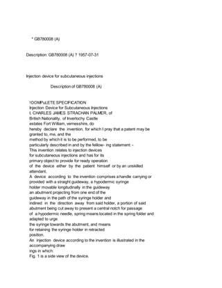
Fig. 1 is a side view of the device.
2. Fig. 2 is a section on the line A A of Fig. 11,
'with the syringe omitted.
Fig. 3 is a section on the line B-B of
Fig 1.
Figs. 4, 5 and 6 are perspective views of
parts of the device.
Referring to the drawings, 1 denotes a
straight guideway attached to a pistol grip
handle 2. 3 denotes a hypodermic syringe
mounted in a holder 4 movable longitudi- wally in the guideway 1. 5
denotes an abutment projecting from one end of the guideway 1 in the
path of the syringe holder 4.
The abutment 5 which consists of a plate
formed with a central notch 6 (Fig. 4) is inclined in the direction
away from the syringe holder 4, to ensure that, when the abutment 5 is
pressed against a patient's skin, a bulge is formed within the notch
6.
The syringe holder 4 includes a pair of spaced clips 7 shaped to
lembrace the barrel of the syringe 3 1and connected by a web 8 to a
base ernber 9 open at the bottorn and engageable with the guideway 1.
The guideway 1 is of channel section having vertical limbs the upper
end portions of which are bent inwardly to define a longitudinal slot
10 (Fig. 5) through which passes the web 8 of the syringe holder 4.
The abutment Si is fixed to a plug 11 insertable into one end portion
of the guide- way 1. One lateral wall of the guideway
1 is formed with a longitudinal slot 12 through which passes a screw
13 threaded into the plug 11 to permit longitudinal adjustment of the
position of the abutment 5 relatively to the guideway 1.l
The lateral walls of the base 9 lof the syringe holder 4 are formed
with registering lengi- tudlnal slots 14 (Fig. 6) through which passes
a transverse pin 15 fixed lin the guideway 1.
A tension spring 1'6 is attached at one end' to the pin 15 and at the
other end to the adjacent end of the base 9 of the holder 4, said
spring 16 being adapted to urge the syringe holder 4 towards the
abutment 5.
A cocking pin 17 passing transversely iof the guideway 1 through
registering longitudinal slots 18 in the lateral walls of said
guideway 1 and through registering orifices 19 (Fig. 6) in the lateral
walls of the base 9 of the syringe holder 4 is adapted to be
manipulated to retract said holder 4 in the guideway 1.
A trigger 20 pivotally mounted on a pin 21 between the lateral walls
of the guideway 1 and depending therefrom through a slot in the base
of the guideway ,1 is formed with a sear 22 engageable with the end of
the base 9 of the syringe holder 4 remote from the spring 16 and
3. adapted to retain said holder 4 in retracted position. A second plug
23 located in the end portion of the guideway 1 remote from rhe
abutment 5 is urged by a compression spring 24 against the trigger 20,
whereby, after retraction of the syringe holder 4, to maintain the
sear 22 in engagement with said holder 4.
In practice, when an injection is to be effected, the cocking pin 1c7
is pulled to retract the syringe holder 4 in opposition to the spring
16 and the trigger 20 is moved to engage the sear 22 with the holder
4.
The patient or an attendant holds the handle 2 in one hand and presses
the abutment 5 against the skin of the patient with sufficient force
to cause a portion of the skin to form a bulge within the cutaway
portion 6 of the abutment 5. The trigger 20 is then pressed to
disengage the sear 22 from the holder 4 which is urged by its
associated spring 16 towards the abutment 5. The needle 25 thereupon
penetrates the bulge in the patient's skin. The travel of the syringe
holder 4 is arrested when the cocking pin 17 comes against the ends of
the registering slots 18 adjacent to the abutment 5. After insertion
of the needle 25, injection into the patient of the contents of the
syringe 3 is effected by depressing the plunger 26 of the syringe 3 in
the normal manner.
The depth of penetration of the needle 25 into the skin may be altered
at will by loosening the screw 13 holding the.plug 11 in position, by
moving the plug 11 longitudinally of the guideway 1, and by tightening
the screw 13 when the abutment 5 is in the desired position.
What I claim is: -
1 An injection device for subcutaneous injections, comprising a handle
carrying or pro 'vided with a straight guideway, a hypodermic syringe
holder movable longitudinally in the guideway, an abutment projecting
from one end of the guideway in the path of the syringe holder and
inclined in the direction away from said holder, a portion of said
abutment being cut away to present a central notch for passage of a
hypodermic needle, spring means located in the syringe holder and
adapted to urge said holder towards the abutment, and means for
holding the syringe holder in retracted position.
2. A device as claimed in claim 1 in which the abutment is fixed to a
plug slidably mounted in one end portion of the guideway one lateral
wall of which latter is formed with a slot through which passes a
screw threaded into the plug.
3. A device as claimed in claim 1 in which the guideway is of channel
section and a cock- ing pin passing through registering 'longitu-
dinal slots in the lateral walls of the guideway and through
registering orifices in a base portion of the syringe holder is
adapted to be manipulated to retract said holder in the guide way.
4. 4 A device as claimed in claims 1 and 3 in which a trigger pivotally
mounted between the lateral walls of the guideway and depending
therefrom through a slot in the base of the guideway is formed with a
sear engageable with the end of the base portion of the syringe holder
remote from the abutment and adapted to hold said holder in retracted
position.
5. A device as claimed in claim 4 in which a plug located in the end
portion of the guideway remote from the abutment is spring urged
against the trigger whereby, when the syringe holder is retracted, to
maintain the trigger in engagement with said holder.
6. An injection device for subcutaneous injections, substantially as
described with reference to the accompanying dr wing. ~~
PROVISIONAL SPECIFICATION
Injection Device for Subcutaneous Injections
I ARLES JAMES STRACHAN PALMER, of
British. Nationality, of Inverlochy Castle
Estate, Fort, William, Inverness-shire, Scotland, do hereby declare
this invention to be described in 'the following statement:
This invention relates to injection apparatus for subcutaneous
injections and has for its primary object to provide for ready
operation of the apparatus either by the patient himself or by an
unskilled attendant.
Apparatus according to the invention comprises a guideway attached to
a handle, a hypodermic syringe holder movable longitudinally in the
guideway, an abutment projecting from one end of the guideway in the
path of the syringe holder, a portion of said abutment being cut away
to permit passage of the needle of the syringe, spring means located
in the syringe holder and adapted to urge the syringe towards the
abutment, and means for retaining the syringe holder in retracted
position.
The syringe holder preferably includes a pair of spaced brackets
shaped to embrace the bar- rel of the syringe and connected by a web
to a base member open at the bottom and engageable with the guideway.
The guideway may be of channel section or may be a hollow cylinder.
The top of the guideway may be formed with a longitudinal slot through
which passes the web of the syringe holder.
The abutment may be fixed to a plug insertable into one end portion.
of the guideway.