SlideShare uma empresa Scribd logo
1 de 555
Baixar para ler offline
TECHNOLOGY IN AC TION™
Arduino
Applied
Comprehensive Projects for
Everyday Electronics
—
Neil Cameron
www.allitebooks.com
Arduino Applied
Comprehensive Projects for
Everyday Electronics
Neil Cameron
www.allitebooks.com
Arduino Applied: Comprehensive Projects for Everyday Electronics
ISBN-13 (pbk): 978-1-4842-3959-9		 ISBN-13 (electronic): 978-1-4842-3960-5
https://doi.org/10.1007/978-1-4842-3960-5
Library of Congress Control Number: 2018965611
Copyright © 2019 by Neil Cameron
This work is subject to copyright. All rights are reserved by the Publisher, whether the whole or
part of the material is concerned, specifically the rights of translation, reprinting, reuse of
illustrations, recitation, broadcasting, reproduction on microfilms or in any other physical way,
and transmission or information storage and retrieval, electronic adaptation, computer software,
or by similar or dissimilar methodology now known or hereafter developed.
Trademarked names, logos, and images may appear in this book. Rather than use a trademark
symbol with every occurrence of a trademarked name, logo, or image we use the names, logos,
and images only in an editorial fashion and to the benefit of the trademark owner, with no
intention of infringement of the trademark.
The use in this publication of trade names, trademarks, service marks, and similar terms, even if
they are not identified as such, is not to be taken as an expression of opinion as to whether or not
they are subject to proprietary rights.
While the advice and information in this book are believed to be true and accurate at the date of
publication, neither the authors nor the editors nor the publisher can accept any legal
responsibility for any errors or omissions that may be made. The publisher makes no warranty,
express or implied, with respect to the material contained herein.
Managing Director, Apress Media LLC: Welmoed Spahr
Acquisitions Editor: Natalie Pao
Development Editor: James Markham
Coordinating Editor: Jessica Vakili
Cover image designed by Freepik (www.freepik.com)
Distributed to the book trade worldwide by Springer Science+Business Media New York,
233 Spring Street, 6th Floor, New York, NY 10013. Phone 1-800-SPRINGER, fax (201) 348-4505,
e-mail orders-ny@springer-sbm.com, or visit www.springeronline.com. Apress Media, LLC is a
California LLC and the sole member (owner) is Springer Science + Business Media Finance Inc
(SSBM Finance Inc). SSBM Finance Inc is a Delaware corporation.
For information on translations, please e-mail rights@apress.com, or visit http://www.apress.
com/rights-permissions.
Apress titles may be purchased in bulk for academic, corporate, or promotional use. eBook
versions and licenses are also available for most titles. For more information, reference our Print
and eBook Bulk Sales web page at http://www.apress.com/bulk-sales.
Any source code or other supplementary material referenced by the author in this book is available
to readers on GitHub via the book’s product page, located at www.apress.com/978-1-4842-3959-9.
For more detailed information, please visit http://www.apress.com/source-code.
Printed on acid-free paper
Neil Cameron
Edinburgh, UK
www.allitebooks.com
iii
About the Author�������������������������������������������������������������������������������xiii
About the Technical Reviewer������������������������������������������������������������xv
Preface���������������������������������������������������������������������������������������������xvii
Table of Contents
Chapter 1: Introduction������������������������������������������������������������������������1
Arduino Uno����������������������������������������������������������������������������������������������������������1
Breadboards����������������������������������������������������������������������������������������������������������3
Arduino IDE Software��������������������������������������������������������������������������������������������4
Arduino IDE Sketch�����������������������������������������������������������������������������������������������5
Run the Blink Sketch���������������������������������������������������������������������������������������������6
Electricity Explained����������������������������������������������������������������������������������������������7
Revise the Blink Sketch����������������������������������������������������������������������������������������8
Pulse Width Modulation��������������������������������������������������������������������������������������12
Opening and Saving Sketches����������������������������������������������������������������������������14
Summary������������������������������������������������������������������������������������������������������������15
Components List�������������������������������������������������������������������������������������������������15
Chapter 2: Switches���������������������������������������������������������������������������17
Tactile Switch������������������������������������������������������������������������������������������������������17
Comparison Operators����������������������������������������������������������������������������������������21
Debouncing a Switch������������������������������������������������������������������������������������������22
Hardware Switch Debounce��������������������������������������������������������������������������������25
www.allitebooks.com
iv
Ball Switch����������������������������������������������������������������������������������������������������������27
Summary������������������������������������������������������������������������������������������������������������29
Components List�������������������������������������������������������������������������������������������������29
Chapter 3: Sensors�����������������������������������������������������������������������������31
Temperature Sensor��������������������������������������������������������������������������������������������31
Variables�������������������������������������������������������������������������������������������������������������35
Humidity Sensor��������������������������������������������������������������������������������������������������37
Library Installation����������������������������������������������������������������������������������������������39
Library Installation Method 1�������������������������������������������������������������������������39
Library Installation Method 2�������������������������������������������������������������������������39
Library Installation Method 3�������������������������������������������������������������������������40
Light Dependent Resistor������������������������������������������������������������������������������������42
Light Dependent Resistor and Several LEDs�������������������������������������������������������46
Voltage Divider����������������������������������������������������������������������������������������������������48
Ultrasonic Distance Sensor���������������������������������������������������������������������������������50
Speed of Sound���������������������������������������������������������������������������������������������������56
Hall Effect Sensor�����������������������������������������������������������������������������������������������57
Sound Sensor������������������������������������������������������������������������������������������������������61
Infrared Sensor���������������������������������������������������������������������������������������������������64
Infrared Distance Module������������������������������������������������������������������������������������67
Passive Infrared Sensor��������������������������������������������������������������������������������������69
Accelerometer and Gyroscope����������������������������������������������������������������������������72
Summary������������������������������������������������������������������������������������������������������������77
Components List�������������������������������������������������������������������������������������������������78
Table of Contents
Table of Contents
www.allitebooks.com
v
Chapter 4: Liquid Crystal Display�������������������������������������������������������79
Contrast Adjustment with PWM��������������������������������������������������������������������������83
Scrolling Text�������������������������������������������������������������������������������������������������������85
LCD with I2C Bus�������������������������������������������������������������������������������������������������87
I2C with Temperature and Pressure Sensor��������������������������������������������������������88
16×4 LCD Cursor Positioning������������������������������������������������������������������������������93
Display Entered Values on LCD���������������������������������������������������������������������������95
LCD Character Set�����������������������������������������������������������������������������������������������96
Additional Characters������������������������������������������������������������������������������������������98
Summary����������������������������������������������������������������������������������������������������������100
Components List�����������������������������������������������������������������������������������������������100
Chapter 5: 7-Segment LED Display���������������������������������������������������101
Basic Schematic�����������������������������������������������������������������������������������������������102
PWM and LED Brightness���������������������������������������������������������������������������������105
Shift Register����������������������������������������������������������������������������������������������������107
Shift Register, PWM, and LED Brightness���������������������������������������������������������113
Alphanumeric Characters���������������������������������������������������������������������������������116
Summary����������������������������������������������������������������������������������������������������������118
Components List�����������������������������������������������������������������������������������������������118
Chapter 6: 4-Digit 7-Segment Display����������������������������������������������119
Functions����������������������������������������������������������������������������������������������������������123
One Shift Register���������������������������������������������������������������������������������������������126
Two Shift Registers�������������������������������������������������������������������������������������������131
Summary����������������������������������������������������������������������������������������������������������135
Components List�����������������������������������������������������������������������������������������������136
Table of Contents
Table of Contents
vi
Chapter 7: 8×8 Dot Matrix Display���������������������������������������������������137
One Shift Register���������������������������������������������������������������������������������������������143
Two Shift Registers�������������������������������������������������������������������������������������������146
Scrolling Text�����������������������������������������������������������������������������������������������������150
Summary����������������������������������������������������������������������������������������������������������156
Components List�����������������������������������������������������������������������������������������������156
Chapter 8: Servo and Stepper Motors����������������������������������������������157
Servo Motors�����������������������������������������������������������������������������������������������������157
Servo Motor and a Potentiometer���������������������������������������������������������������������161
Stepper Motor���������������������������������������������������������������������������������������������������165
Stepper Motor and a Potentiometer������������������������������������������������������������������172
Stepper Motor Gear Ratio���������������������������������������������������������������������������������175
Summary����������������������������������������������������������������������������������������������������������176
Components List�����������������������������������������������������������������������������������������������176
Chapter 9: Rotary Encoder����������������������������������������������������������������177
Rotary Encoder and Stepper Motor�������������������������������������������������������������������182
Summary����������������������������������������������������������������������������������������������������������186
Components List�����������������������������������������������������������������������������������������������187
Chapter 10: Infrared Sensor�������������������������������������������������������������189
Infrared Emitter and Sensor������������������������������������������������������������������������������195
Infrared Emitter and Receiver���������������������������������������������������������������������������197
Summary����������������������������������������������������������������������������������������������������������200
Components List�����������������������������������������������������������������������������������������������201
Chapter 11: Radio Frequency Identification�������������������������������������203
Display Content of MIFARE Classic 1K and 4K��������������������������������������������������205
Mimic RFID and Secure Site�����������������������������������������������������������������������������208
Table of Contents
Table of Contents
vii
Master Card Validation��������������������������������������������������������������������������������������211
Read and Write to Classic 1KB Card�����������������������������������������������������������������213
Summary����������������������������������������������������������������������������������������������������������217
Components List�����������������������������������������������������������������������������������������������217
Chapter 12: SD Card Module�������������������������������������������������������������219
Temperature and Light Intensity Logging���������������������������������������������������������220
Date and Time Logging�������������������������������������������������������������������������������������226
Logging Weather Station Data��������������������������������������������������������������������������228
Increment File Name for Data Logging�������������������������������������������������������������232
Listing Files on an SD Card�������������������������������������������������������������������������������234
Summary����������������������������������������������������������������������������������������������������������236
Components List�����������������������������������������������������������������������������������������������236
Chapter 13: Screen Displays�������������������������������������������������������������237
TFT LCD Screen�������������������������������������������������������������������������������������������������237
Displaying Images from an SD Card�����������������������������������������������������������������242
Screen, Servo Motor, and Ultrasonic Distance Sensor��������������������������������������243
OLED Display�����������������������������������������������������������������������������������������������������249
Touch Screen����������������������������������������������������������������������������������������������������252
Summary����������������������������������������������������������������������������������������������������������258
Components List�����������������������������������������������������������������������������������������������259
Chapter 14: Sensing Colors��������������������������������������������������������������261
Red Green Blue (RGB) LED��������������������������������������������������������������������������������262
565 Color Format����������������������������������������������������������������������������������������������264
Color-Recognition Sensor���������������������������������������������������������������������������������267
Summary����������������������������������������������������������������������������������������������������������275
Components List�����������������������������������������������������������������������������������������������275
Table of Contents
Table of Contents
viii
Chapter 15: Camera��������������������������������������������������������������������������277
Camera Image Capture Setup���������������������������������������������������������������������������281
Capturing Camera Images��������������������������������������������������������������������������������285
Summary����������������������������������������������������������������������������������������������������������288
Components List�����������������������������������������������������������������������������������������������288
Chapter 16: Bluetooth Communication���������������������������������������������289
Bluetooth Terminal HC-05 App��������������������������������������������������������������������������292
ArduDroid App���������������������������������������������������������������������������������������������������295
Message Scrolling with MAX7219 Dot Matrix Module��������������������������������������300
MAX7219 and Bluetooth Terminal HC-05 App���������������������������������������������������302
Message Speed and Potentiometer������������������������������������������������������������������306
MAX7219 and ArduDroid App����������������������������������������������������������������������������307
Summary����������������������������������������������������������������������������������������������������������310
Components List�����������������������������������������������������������������������������������������������310
Chapter 17: Wireless Communication����������������������������������������������311
Transmit or Receive������������������������������������������������������������������������������������������315
Transmit and Receive����������������������������������������������������������������������������������������317
Summary����������������������������������������������������������������������������������������������������������322
Components List�����������������������������������������������������������������������������������������������323
Chapter 18: Build Arduino����������������������������������������������������������������325
ATmega328P Pin Layout�����������������������������������������������������������������������������������326
Building an Arduino�������������������������������������������������������������������������������������������328
Installing the Bootloader�����������������������������������������������������������������������������������332
Summary����������������������������������������������������������������������������������������������������������336
Components List�����������������������������������������������������������������������������������������������337
Table of Contents
Table of Contents
ix
Chapter 19: Global Navigation Satellite System�������������������������������339
GNSS Messages on Serial Monitor�������������������������������������������������������������������339
u-blox u-center�������������������������������������������������������������������������������������������������341
Arduino and GNSS���������������������������������������������������������������������������������������������343
GNSS Data Logging to SD Card�������������������������������������������������������������������������357
GNSS and ST7735 Screen���������������������������������������������������������������������������������360
Displaying GNSS Data���������������������������������������������������������������������������������������368
Summary����������������������������������������������������������������������������������������������������������369
Components List�����������������������������������������������������������������������������������������������369
Chapter 20: Interrupts and Timed Events�����������������������������������������371
Interrupts����������������������������������������������������������������������������������������������������������371
Types of Interrupt����������������������������������������������������������������������������������������������376
Additional Interrupt Pins�����������������������������������������������������������������������������������379
Interrupts and Rotary Encoder��������������������������������������������������������������������������380
Timed Events: delay()���������������������������������������������������������������������������������������384
Timed Events: millis()���������������������������������������������������������������������������������������384
Timed Events: Timer1����������������������������������������������������������������������������������������387
Timer Register Manipulation�����������������������������������������������������������������������������390
Summary����������������������������������������������������������������������������������������������������������395
Components List�����������������������������������������������������������������������������������������������395
Chapter 21: Power Saving����������������������������������������������������������������397
avr/sleep Module����������������������������������������������������������������������������������������������402
LowPower Library���������������������������������������������������������������������������������������������405
Power Down and an Infrared Sensor����������������������������������������������������������������406
Summary����������������������������������������������������������������������������������������������������������410
Components List�����������������������������������������������������������������������������������������������410
Table of Contents
Table of Contents
x
Chapter 22: Sound and Square Waves����������������������������������������������411
Piezo Transducer and Buzzer����������������������������������������������������������������������������416
Musical Notes���������������������������������������������������������������������������������������������������416
Sensor and Sound���������������������������������������������������������������������������������������������420
Generating Square Waves���������������������������������������������������������������������������������425
Square Wave and Servo Motor��������������������������������������������������������������������������431
Summary����������������������������������������������������������������������������������������������������������432
Components List�����������������������������������������������������������������������������������������������432
Chapter 23: DC Motors����������������������������������������������������������������������433
Motor Control Set in the Sketch������������������������������������������������������������������������438
Motor Speed������������������������������������������������������������������������������������������������������441
Motor Control with Infrared Remote Control�����������������������������������������������������444
Motor Control with Wireless Communication����������������������������������������������������445
Motor Control with Accelerometer��������������������������������������������������������������������452
Motor Control with Photoelectric Encoder��������������������������������������������������������457
Summary����������������������������������������������������������������������������������������������������������465
Components List�����������������������������������������������������������������������������������������������465
Chapter 24: Robot Car����������������������������������������������������������������������467
PID Controller����������������������������������������������������������������������������������������������������475
Balancing Robot������������������������������������������������������������������������������������������������481
Determining PID Coefficients����������������������������������������������������������������������������483
Circular Buffer���������������������������������������������������������������������������������������������������485
Quaternion Measurements��������������������������������������������������������������������������������489
Summary����������������������������������������������������������������������������������������������������������496
Components List�����������������������������������������������������������������������������������������������497
Table of Contents
Table of Contents
xi
Chapter 25: Wi-Fi Communication����������������������������������������������������499
NodeMCU ESP8266�������������������������������������������������������������������������������������������499
WeMos D1 Mini�������������������������������������������������������������������������������������������������502
Wi-Fi and Web Server���������������������������������������������������������������������������������������504
Wi-Fi and HTML�������������������������������������������������������������������������������������������������510
Wi-Fi and Internet Access���������������������������������������������������������������������������������519
Summary����������������������������������������������������������������������������������������������������������530
Components List�����������������������������������������������������������������������������������������������531
Appendix: Resistor Banding�������������������������������������������������������������533
Libraries������������������������������������������������������������������������������������������������������������534
Quaternion Measurements��������������������������������������������������������������������������������537
Who’s Who in Electronics����������������������������������������������������������������������������������541
Sources of Electronic Components�������������������������������������������������������������������542
Index�������������������������������������������������������������������������������������������������545
Table of Contents
Table of Contents
xiii
About the Author
Neil Cameron was a research scientist in quantitative genetics at Roslin
Institute (of “Dolly the sheep” fame) with expertise in data analysis and
computer programming. Neil has taught at the University of Edinburgh
and Cornell University. He has a deep interest in electronics and “how
things work,” with a focus on programming the Arduino and its application
on a range of comprehensive projects for everyday electronics, which
inspired him to write this book.
xv
About the Technical Reviewer
Fabio Claudio Ferracchiati is a senior consultant and a senior analyst/
developer using Microsoft technologies. He works at BluArancio S.p.A
(www.bluarancio.com) as senior analyst/developer and Microsoft
Dynamics CRM Specialist. He is a Microsoft Certified Solution Developer
for .NET, a Microsoft Certified Application Developer for .NET, a Microsoft
Certified Professional, and a prolific author and technical reviewer.
Over the past ten years, he’s written articles for Italian and international
magazines, and co-authored more than ten books on a variety of
computer topics.
xvii
Preface
Microcontrollers are incorporated in car control systems, domestic
appliances, office machines, mobile phones, medical implants, remote
controls, and the list goes on. The Arduino Uno is a microcontroller board
that can be easily programmed and used to build projects. The objective
of this book is to provide information to use the Arduino Uno in a range
of applications, from blinking an LED to a motion sensor alarm, to route
mapping with a mobile GPS system, to uploading information to the
Internet. Prior knowledge of electronics is not required, as each topic is
described and illustrated with examples using the Arduino Uno.
The book covers a comprehensive range of topics. In Chapters 1–3,
the Arduino Uno and the Arduino programming environment are set
up, and several sensors are described with practical examples to provide
the basis for subsequent projects. Information display with the Arduino
Uno using liquid crystal, LED, and dot matrix displays are described in
Chapters 4–7. Several projects are developed with servo and stepper
motors, infrared control, RFID, and SD card data logging in Chapters 8–12.
Sensing and displaying color is outlined in Chapters 13–14, and recording
images in Chapter 15. Bluetooth, wireless, and Wi-Fi communication
systems are described in Chapters 16, 17 and 25, with practical examples
of message scrolling, servo motor control, and web-based information
display projects, respectively. The Arduino Uno is deconstructed to the
microcontroller for use in a mobile GPS system, with timed events and
power-saving methods in Chapters 18–21. Electronic sound projects are
outlined in Chapter 22. An obstacle-avoiding robot car and a balancing
robot are described in Chapters 23 and 24, with the robot car controlled by
systems described in earlier chapters.
xviii
Projects covered in the book include and extend those in Arduino
Uno starter kits to increase knowledge of microcontrollers in electronic
applications. Many of the projects are practically orientated, such as
information displays, GPS tracking, RFID entry systems, motion detector
alarms, and robots. Building projects helps you understand how many
electronic applications function in everyday life. Examples include flashing
numbers on a screen, a scrolling message in the train station, electronic
tags on items in a shop or books in the library, a desktop weather station,
Bluetooth communication with a mobile phone, digital sound systems,
and an obstacle-avoiding robot vacuum cleaner.
Each example in the book is accompanied by code and a description
of that code, which helps you learn how to program a microcontroller and
a computer, which is a highly valuable skill. The Arduino programming
language is C, which is widely used. Learning to program an Arduino
provides the framework for other computer programming languages.
Throughout the book, schematic diagrams were produced with Fritzing
software (www.fritzing.org), with an emphasis on maximizing the clarity
of component layout and minimizing overlapping connections. The
authors of the libraries used in the book are identified in each chapter,
with library details covered in the appendix. There are several approaches
to structuring sketches, and the approach taken in the book is to declare
variables at the start of the sketch, rather than throughout the sketch.
All the code used in the book is available to download from github.
com/Apress/arduino-applied. The Arduino programming environment
and libraries are constantly being updated, so information on the
consequences of those updates on the content of the book is also available
at github.com/Apress/arduino-applied.
Many chapters of the book are stand-alone, so that you can delve
into a section of the book rather than having to start from the beginning,
while several chapters utilize information from earlier chapters to build
a project. You learn how to break down a complex project into smaller
Preface
Preface
xix
projects, just as each chapter addresses a different topic, to then be able to
build and enhance the initial project.
If you bought, or are thinking about buying, an Arduino Uno starter
kit that contains a few LEDs, a variety of sensors, with some switches and
resistors, then this book is for you. If you want to build electronics projects
with a microcontroller, then the comprehensive range of topics covered in
the book provides the detailed instructions to get started.
Preface
Preface
1
© Neil Cameron 2019
N. Cameron, Arduino Applied, https://doi.org/10.1007/978-1-4842-3960-5_1
CHAPTER 1
Introduction
The Arduino Uno provides the framework to learn about electronics, and to
understand and build electronic devices. The Arduino Uno can monitor an
environment with sensors, drive LED message boards, generate sound and
light patterns, take and display digital photos, communicate by Bluetooth
or wirelessly with other electronic devices, communicate by Wi-­
Fi to the
Internet, and record data on the route, speed, and altitude of a trip with GPS.
Arduino Uno
The Arduino Uno R3 (see Figure 1-1) contains the ATmega328P
microcontroller to carry out programmed instructions and memory
to store data. The Arduino is powered through a DC input or a USB
connection, which is also used to upload instructions and communicate
with a computer or laptop. An ATmega16U2 chip manages USB (Universal
Serial Bus) to serial communication.
The power pins allow 5V (5 volts) or 3.3V and ground (GND) to
connect other devices. Pins 0 and 1 are for transmitting and receiving
serial data from other devices. Pins 2 to 13 are digital input and output,
which input or output 5V for a digital one or 0V for a digital zero. Several
output pins vary the time that a pin state is 5V to emulate voltages between
0V and 5V. The analog pins, A0 to A5, measure voltages between 0V and
5V and convert analog signals to digital values (ADC). Pins A4 and A5
2
can also communicate with other devices, as can pins 10 to 13, but using
different communication systems, I2C and SPI respectively, than the
USB connection. Three LEDs (light-emitting diode) indicate power (ON),
transmitting (TX), and receiving (RX), with a fourth LED connected to pin 13.
The Reset button is used to restart the microcontroller.
The functionality of the Arduino Uno enables a comprehensive range
of projects to be developed, which are described throughout the book.
Several of the terms—such as ADC, I2C, and SPI—may mean little to you
just now, but they are explained in the relevant chapters.
Figure 1-1. Arduino Uno
Chapter 1 Introduction
3
Breadboards
The solderless breadboard contains columns of connected sockets for
positioning electronic components to create a circuit and for connecting to
the Arduino (see Figure 1-2). The two rows along the length (left to right)
of the breadboard are used to connect to power (red) or ground (blue)
lines in a circuit. Holes in each short column (green) of the breadboard
are connected together, but the columns are not connected, so that two
components each with one “leg” in the same green column are connected
together. The middle area in the breadboard separates the breadboard into
two unconnected halves. Breadboards come in a variety of sizes.
Figure 1-2. Breadboard
The term breadboard originates from radio amateurs attaching
fixing points to a wooden breadboard and then connecting electronic
components to the fixing points.
For example, Figure 1-3 shows a circuit with an LED, a 100Ω resistor,
and a 3V battery. The positive or red terminal of the 3V battery is
connected to the long leg of the LED, as the relevant component legs are
in the same short column. Likewise, the short leg of the LED is connected
to the “top” end of the 100Ω resistor, but not to the “bottom” end of the
Chapter 1 Introduction
4

Arduino IDE Software
The Arduino IDE (interactive development environment) software
is downloaded from www.arduino.cc/en/Main/Software, with the
downloaded arduino-version number-windows.exe file saved to the
desktop. The .exe file is double-clicked to start the installation.
The Arduino IDE program files are stored in C: ➤ Program Files (x86)
➤ Arduino, which includes example sketches located in C: ➤ Program
Files (x86) ➤ Arduino ➤ examples. Each example sketch is accompanied
by a text file outlining the objective of the sketch, the breadboard layout of
the components, and a circuit diagram.
The Arduino IDE is used to write, compile, and upload files to the
microcontroller. A file containing Arduino code is called a sketch. Within the
Arduino IDE, clicking one of the five IDE symbols
provides quick access to compile a sketch, to compile and upload a sketch,
to open a blank sketch, to open an existing sketch from a list of all sketches,
Figure 1-3. LED and resistor circuit
resistor due to the separating middle area of the breadboard. To complete
the circuit, a black wire connects the negative or black terminal of the 3V
battery to the “bottom” end of the resistor.
Chapter 1 Introduction
5
and to save the current sketch. The Open an existing sketch option
does not scroll the complete list of sketches, so use File ➤ Sketchbook
instead. Some useful options from the drop-down menu are given in
Table 1-1.
Table 1-1. Drop-down Menu Options of the Arduino IDE
Options Description
File ➤ Open Recent A list of recently accessed sketches
File ➤ Examples Arduino IDE built-in sketches
Edit ➤ Find Find and replace text in a sketch
Sketch ➤ Include Library Arduino and contributed libraries
Tools ➤ Serial Monitor Displays serial data to serial monitor
Tools ➤ Serial Plotter Graphic display of serial data
Tools ➤ Board Description of the microcontroller
for example Arduino/Genuino Uno
Tools ➤ Port Detail of serial port,
for example COM3 Arduino/Genuino Uno
File ➤ Open Recent List of recently accessed sketches

Arduino IDE Sketch
An Arduino IDE sketch consists of three parts: variable definition, the
void setup(), and the void loop() functions. The first part includes
defining which Arduino pins are connected to sensors, LEDs, or devices,
and declaring the values of variables. For example, the int LEDpin = 9
instruction defines a variable, named LEDpin, with the integer value of 9.
The void setup() function implements definitions in the first part of the
Chapter 1 Introduction
6
sketch and only runs once. For example, the pinMode(LEDpin, OUTPUT)
instruction defines the Arduino pin 9 as an output pin, rather than an
input pin by default, since LEDpin has the value 9.
The void loop() function runs continuously and implements the
sketch instructions. For example, a sketch may turn on and off an LED at
given times.
Declaring variables in the first part of the sketch makes it easier to
update the variable once at the start of the sketch, rather than having to
check through the sketch and update variables throughout the sketch.
Comments are prefaced by //, such as // Set LED to pin 9, and are
not implemented by the microcontroller. With a couple of exceptions, all
instruction lines end with a semicolon.

Run the Blink Sketch
Follow these steps to run the blink sketch.
1. Connect the Arduino to a computer or laptop with
the USB-to-serial cable.
2. In Arduino IDE, select File ➤ Examples ➤ 01. Basics ➤ Blink.
3. Click the Compile and Upload, , button.
The built-in LED on the Arduino will now flash every second. Welcome
to Arduino !
The error message indicates that the serial
port should be updated. Select Tools ➤ Port and choose the appropriate
port (for example, COM3 or COM4) for the Arduino. Go to step 3.
The error message indicates
that the description of the microcontroller should be updated. Select
Tools ➤ Board and choose the relevant board (for example, Arduino/
Genuino Uno). Go to step 3.
Chapter 1 Introduction
7
Electricity Explained
An understanding of electricity is helpful before progressing further.
All materials are made of atoms, which consist of protons, neutrons,
and electrons. Electrons have a negative charge and can move from one
atom to another. Electricity is the movement of electrons between atoms,
or rather the flow of an electrical charge.
A simple example of an electrical charge is rubbing a cloth over an
inflated balloon. Electrons are rubbed off the cloth and onto the balloon,
making the balloon negatively charged. If the balloon is now placed near
an object, then the balloon “sticks” to the object. The negative charge of
the balloon repels the negatively charged electrons of the object, leaving
an excess of positive charge next to the balloon. Since positive and
negative charges attract, then the balloon is attracted to the object.
The effect of moving an electric charge from one object to another has
been known for centuries. More than two-and-a-half-thousand years ago,
the Greeks knew that rubbed amber, which is fossilized tree resin, could
attract light objects, such as hair. The word electric derives from the Greek
word for amber, elektron.
A discharging battery is a source of electrons, and the electrons
move from the negative terminal, the anode, to the positive terminal, the
cathode. The words anode and cathode are derived from the Greek words
anodos and kathodos, so cathode is abbreviated as K. Although electrons
flow from anode to cathode, the conventional current flows from cathode
to anode, or from positive to negative.
Describing electricity uses the terms charge, voltage, current, and
resistance. The analogy of water flowing from a reservoir through a pipe
can be used to envisage some of the electrical terms (see Table 1-2).
Chapter 1 Introduction
8
The relationship between voltage (V), current (I), and resistance (R) is
V = I × R, which is Ohm’s law.
Charge is measured in amp-hours (Ah), which is the charge
transferred by a current of one amp for one hour. The length of time that a
battery, such as a nickel metal hydride (NiMH) AA battery with a charge of
2400mAh, can supply a given current depends on the size of the current.
For example, with discharge rates of 2400, 4800, or 7200mAh, the battery
would last 60, 30, or 20 minutes.
Electrical power, measured in watts (W), is the rate that energy is
transferred in unit time, equal to the product of voltage and current.

Revise the Blink Sketch
The blink sketch can be changed to make a separate
LED blink rather than the LED on the Arduino. The
Arduino supplies a regulated 5V output from the pin
marked 5V, but a resistor is required to ensure that the
current does not exceed the LED’s maximum permitted
current of 20mA. Without the resistor, the high current
would damage the LED.
Using Ohm’s law, which states voltage equals the product of current
and resistance, or V = I × R, the value of the resistor (R) can be determined,
Table 1-2. Electrical Parameter and Water Analogy
Electrical Parameter Water Analogy
Electrical charge (coulombs, C) Amount of water in the reservoir
Voltage (volts, V) Water pressure at the reservoir end of the pipe
Current (amperes or amps, A) Rate of water flow
Resistance (ohms, Ω) Inverse of pipe width
(narrow pipe ⇒ high resistance)
Chapter 1 Introduction
9
given the known voltage (V) and current (I). The forward voltage drop
across the LED is 2V, which is the minimum voltage required to turn on the
LED. With a 5V output from the Arduino, there is 3V = 5V – 2V across the
resistor (see Figure 1-4). If the current through the resistor and the LED is
to be at most 20mA, then from Ohm’s law, the resistor value (R = V/I) =
3/0.02 = 150Ω, which is equal to the voltage across the resistor divided
by the current through the resistor. A resistor of at least 150Ω would
protect the LED from an excessively high current and the widely available
220Ω resistor can be used. Resistors are color-coded (see Appendix) to
identify the resistance, but checking the resistance with a multimeter is
straightforward. Resistors are connected either way around in a circuit.
The power through the resistor should be checked to ensure that it
is not greater than the maximum value for the resistor. In the example,
the maximum power rating of the resistor is 250mW. With 3V across the
resistor and 20mA maximum current, then power = V × I = 60mW, which is
well below the maximum value.
An LED is a diode, which allows current to pass in one direction only.
The long leg of the LED is the anode and the flat side of the LED is on the
cathode side. LEDs contain semiconductor material, which determines
the wavelength of light emitted: red, green, blue, or yellow. The forward
voltage drop of red, yellow, and green LEDs is lower than for blue and
white LEDs: 2.0V and 2.9V, respectively.
If an LED and resistor were connected as in the left-hand side of
Figure 1-4, then the LED would stay on continuously. If the LED was
connected to an Arduino pin, then changing the pin status from 5V (HIGH)
to 0V (LOW) to HIGH repeatedly would turn on and off the LED. The
revised circuit in the right-hand side of Figure 1-4 has the LED anode
connected to pin 11 of the Arduino. Switching the LED on and off is a
digital or binary operation, 0 or 1, requiring a digitalWrite instruction to
pin 11 to enable or disable a power supply to the LED. Connections for the
two examples in Figure 1-4 are given in Table 1-3.
Chapter 1 Introduction
10
Figure 1-4. Blink an LED
Table 1-3. Connections for LED
Component Figure 1-4 left-hand side Figure 1-4 right-hand side
Connect to and to Connect to and to
LED long leg Arduino 5V Arduino pin 11
LED short leg 220Ω resistor Arduino GND 220Ω resistor Arduino GND
The revised blink sketch is shown in Listing 1-1. The LED is connected
to Arduino pin 11. In the void setup() function, the Arduino pin defined
by the LEDpin variable is defined as an OUTPUT pin, rather than an INPUT
pin that would be used for input, such as measuring a voltage. In the
void loop() function, the state of Arduino pin 11 is repeatedly changed
from HIGH to LOW and LOW to HIGH at one-second intervals, which
corresponds to changing the output voltage on the pin from 5V to 0V, and
so the LED turns on and off.
Chapter 1 Introduction
11
Listing 1-1. Sketch to Blink an LED
int LEDpin = 11;              //defineLEDpinwithintegervalue11
void setup()                  // setup function runs once
{
  pinMode(LEDpin, OUTPUT);    // define LEDpin as output
}
void loop()                   // loop function runs continuously
{
  digitalWrite(LEDpin, HIGH);   //setpinstateHIGHtoturnLEDon
  delay(1000);                
// wait for a second = 1000ms
  digitalWrite(LEDpin, LOW);  // set pin state LOW to turn LED off
  delay(1000);
}
Instructions within the void setup() and void loop() functions are
included in curly brackets, indicating the start and end of the function,
with the instructions indented to make the sketch easier to interpret.
Sketches must include both the void setup() and void loop() functions,
even if a function contains no instructions.
Comments are useful to interpret a sketch. A comment is text after the
// characters. Several lines of comments can be included when bracketed
by /* and */, such as
/* this is the first line of comment
this is the second line of comment
this is the last line of comment */
The schematic format has red and black wires for VCC (positive
voltage) and GND (ground), with yellow, blue, or green wires connecting
electronic components to Arduino pins. In general, green is used for an
input signal and yellow for an Arduino output signal.
Chapter 1 Introduction
12

Pulse Width Modulation
Several Arduino pins, those marked with ~ support Pulse Width
Modulation (PWM), which replaces a constant HIGH signal with a square
wave, pulsing HIGH and LOW, and the pulse width can be modified (see
Figure 1-5). The impact of PWM on an LED is to change the perceived
continuous brightness of an LED, even though the LED is being turned on
and off repeatedly.
PWM is also used to control the speed of motors and to generate
sound. The PWM frequency on Arduino pins 5 and 6 is 976 cycles per
second (Hertz or Hz), so the interval between pulses, indicated by the
green dotted lines in Figure 1-5, is 1.024ms. Most people cannot detect
flicker between images displayed above 400Hz, so an LED turned on and
off at 976Hz appears to be constantly on.
The square wave is generated by the analogWrite(pin, value)
instruction with a duty cycle of (value/255), so a 0% or 100% duty cycle
corresponds to a value of 0 or 255. For example, in Figure 1-5, with a 5V
supply, the PWM duty cycles of 0%, 25%, 50%, 75%, and 100% can be
broadly thought of as supplying average voltages of 0V, 1.25V, 2.5V, 3.75V,
and 5V, respectively. PWM is one mechanism for supplying “analog”
signals from a “digital” 0V or 5V signal, and it is used in many projects
throughout the book.
Chapter 1 Introduction
13
The sketch (see Listing 1-2) uses PWM to change the brightness of an
LED with the rate of change controlled by the increm and time variables.
Listing 1-2. LED Brightness and PWM
int LEDpin = 11;            // define LED pin
int bright = 0;              // initial value for LED brightness
int increm = 5;              //incrementalchangeinPWMfrequency
int time = 25;                //definetimeperiodbetweenchanges
void setup()                // setup function runs once
{
  pinMode(LEDpin, OUTPUT);  // LED pin as output
}
Figure 1-5. Pulse width modulation
Chapter 1 Introduction
14
void loop()                     // loop function runs continuously
{
  analogWrite(LEDpin, bright);  // set LED brightness with PWM
  delay(time);                  // wait for the time period
  bright = bright + increm;     // increment LED brightness
  if(bright =0 || bright = 255) increm = - increm;
}                      // reverse increment when brightness = 0 or 255
The symbols || denote OR, so the if(bright = 0 || bright = 255)
increm = -increm instruction is equivalent to “if the bright variable is
less than or equal to zero, or greater than or equal to 255, then change the
sign of the increm variable.” The OR instruction reverses the increasing
brightness to decreasing brightness, and vice versa.

Opening and Saving Sketches
To open a saved sketch, within the Arduino IDE, select File ➤ Open.
Choose the folder name containing the sketch, click Open, select the
sketch, and click Open. Alternatively, select File ➤ Open Recent. A list of
recently opened sketches is displayed, then click the required sketch.
The default location for saving sketches is determined by selecting
File ➤ Preferences in the Arduino IDE. To save a sketch, select File ➤ Save As,
which opens the default sketches folder, then choose a file name for the
sketch and click Save. The file name must not contain spaces, so use an
underscore instead, such as in file_name. When a sketch is saved, a folder
is automatically generated to contain the sketch.
When a sketch has been edited in the Arduino IDE, a § symbol follows
the sketch name to indicate that changes have been made since the sketch
was last saved. To save an existing sketch, select File ➤ Save. If changes
have been made to a sketch, then after saving the sketch, the § symbol
disappears.
Chapter 1 Introduction
15
Summary
The Arduino Uno and the Arduino IDE programming environment were
described. An introduction to programming the Arduino enabled a sketch
to control an LED turning on and off. The blink sketch was changed to
vary the brightness of the LED using Pulse Width Modulation. A summary
of electricity, including Ohm’s Law, helped you understand how an LED
functions and that an LED requires a resistor to reduce the current.
Components List
• Arduino Uno and breadboard
• LED
• Resistor: 220Ω
Chapter 1 Introduction
17
© Neil Cameron 2019
N. Cameron, Arduino Applied, https://doi.org/10.1007/978-1-4842-3960-5_2
CHAPTER 2
Switches
Switches are used to turn devices on or off, such as a room light or an
electrical appliance, and when sending a signal, such as pressing a
particular key on a keyboard. Switches can also be used to control devices;
a device is on when the switch is initially pressed or while the switch is
pressed. The metal contacts of switches can bounce when the switch is
pressed, which could repeatedly turn a device on and off again. Switch
bouncing can be controlled using software or by hardware, which is called
debouncing a switch.
Tactile Switch
A switch can be connected to an Arduino pin to turn an LED
on or off. When the switch is closed, the digital pin is
connected to 5V and the pin state is HIGH. When the switch
is open, the 10kΩ pull-down resistor permits a small current
to flow between the digital pin and GND, so the pin state is
pulled down to LOW (see Figure 2-1).
18
If the switch and resistor are reversed, relative to the digital pin, then
when the switch is open, the digital pin is connected to 5V, through the 10kΩ
pull-up resistor, and the pin state is HIGH. Use of a pull-down or a pull-up
resistor depends on whether the pin state is to be LOW or HIGH when the
switch is open. If a pull-down or pull-up resistor was not included, then
when the switch is open the digital pin would not be connected to GND or to
5V, so the pin state would be undefined. Incorporation of a switch with the
pull-down resistor is shown in Figure 2-­2.
Figure 2-1. Pull-down resistor
Chapter 2 Switches
19
Figure 2-2. LED switch with pull-down resistor
Table 2-1. Connections for LED Switch with Pull-Down Resistor
Component Connect to and to
Switch left Arduino 5V
Switch right Arduino pin 8
Switch right 10kΩ resistor Arduino GND
LED long leg Arduino pin 4
LED short leg 220Ω resistor Arduino GND
The switch module consists of two pairs of connected pins, with the
switch pins close together on the underside of the switch. Connections for
Figure 2-2 are given in Table 2-1.
Chapter 2 Switches
20
Listing 2-1 turns an LED on while the switch is pressed and off while
the switch is not pressed. The digitalRead(pin number) instruction reads
the state of the pin, HIGH or LOW.
Listing 2-1. LED Switch
int switchPin = 8;                  // define switch pin
int LEDpin = 4;                     // define LED pin
int reading;                        // 
define reading as integer
void setup()
{
  pinMode(LEDpin, OUTPUT);          // LED pin as output
}
void loop()
{
  reading = digitalRead(switchPin); // read switch pin
  digitalWrite(LEDpin, reading);    // turn LED on if switch is HIGH
}                                   
// 
turn LED off if switch is LOW
It would be more useful to turn the LED on or off only when the switch
is pressed (see Listing 2-2). The states of the switch and LED are stored
as variables, switchState and LEDState, respectively. When the switch is
initially pressed, the switch state changes from LOW to HIGH and the
state of the LED is updated from either LOW (off) to HIGH (on) or from
HIGH to LOW. The switchState variable is also updated when the switch is
initially pressed, but if the switch is continuously pressed, then the switch
state does not change. Releasing the switch changes the switch state from
HIGH to LOW and the switchState variable is updated, but there is no
change in the LED state. The void loop() function continues to read the
switch pin.
Chapter 2 Switches
21
Listing 2-2. LED Switch Only When Pressed
int switchPin = 8;                  // define switch pin
int LEDpin = 4;                     // define LED pin
int reading;                        // 
define reading as an integer
int switchState = LOW;              // set switch state to LOW
int LEDState = LOW;                 // set LED state to LOW
void setup()
{
  pinMode(LEDpin, OUTPUT);          // LED pin as output
}
void loop()
{
  reading = digitalRead(switchPin); // read switch pin
  if(reading != switchState)        // if switch state has changed
  {                                 // if switch pressed, change LED state
    if(reading == HIGH  switchState == LOW) LEDState = !LEDState;
    digitalWrite(LEDpin, LEDState); // turn LED on or off
    switchState = reading;          // update switch state
  }
}
Comparison Operators
A logical AND is indicated with the  symbol, such as if(XY  A==HIGH),
which indicates that if X is greater than Y and A is equal to HIGH, then the
outcome is true.
A logical OR is indicated with the || symbol, such as if(XY || A==HIGH),
which indicates that if X is greater than Y or A is equal to HIGH, then the
outcome is true.
Chapter 2 Switches
22
The double equals sign (==) denotes “is equal to” in a comparison, as
in if(reading == HIGH), which means “if reading is equal to HIGH”
.
!= denotes “is not equal to” in a comparison as in if(reading !=
switchState), which means “if reading is not equal to switchState”
.
The exclamation mark ! denotes “the opposite value”
, as in LEDState =
!LEDState, which means “change LEDstate to its opposite value”
, which is
from HIGH to LOW or LOW to HIGH.
The equivalent of X = X + 1 is X++ and similarly, X-- is equivalent to
X = X - 1.
The calculation y%x is y modulus x, or the remainder when integer y is
divided by integer x.
Debouncing a Switch
When a switch is pressed, the springy nature of the metal used in the
contact points can cause the contact points to touch several times; in
other words, to bounce, before making a permanent contact. The Arduino
clock speed of 16MHz equates to 16 million operations per second, so a
bouncing switch contact appears to the microcontroller as having closed
and opened several times when the switch is pressed. For example, when
an LED is controlled by a switch, sometimes the LED does not turn on
or off when the switch is pressed. The switch can be debounced by two
software methods or by a hardware solution.
One software method initiates a delay, following a change in the switch
state, and then rereads the switch state after the delay, defined by the
delay(milliseconds) instruction. If the delay is too short, then the switch
may still be bouncing at the end of the delay. The void loop() function in
Listing 2-3 includes the debounce delay, rereads the switch pin and compares
the new switch state with the switch state read before the delay. In Listing 2-3,
the new instructions compared to Listing 2-2 are highlighted in bold.
Chapter 2 Switches
23
Listing 2-3. LED Switch with Debounce Time
void loop()
{
  reading = digitalRead(switchPin);  // read switch pin
  if(reading != switchState)         // if state of switch has changed
  {
    delay(50);                         // debounce time of 50ms
    reading = digitalRead(switchPin);  // read switch pin again
    if(reading != switchState)         // compare switch state again
    {
      if (reading == HIGH  switchState == LOW) LEDState =!LEDState;
       digitalWrite(LEDpin, LEDState);
       switchState = reading;
    }
  }
}
A second software method is to continue delaying until there is no
longer a change in the switch state at the end of the delay or debounce time.
The debounce time is essentially the time that the switch must be held in
a constant state before the LED is turned on or off. The state of the switch
has to be stored at three times: before the switch was pressed (oldSwitch),
when the switch was pressed during the debounce time (switchState) and
when the switch was last pressed (reading). The millis() function counts
the number of milliseconds that the sketch has been running and is used
to store the time when the switch was pressed. The state of the switch is
continuously read, until the switch state is the same for longer than the
debounce time, at which time the LED can be turned on or off. The number
of milliseconds may be greater than the upper limit of an integer number
(215
–1)ms or 33 seconds, so the time variable is defined as an unsigned long
with maximum value of (232
–1)ms or 50 days.
Chapter 2 Switches
24
In Listing 2-4, lastSwitch refers to the time the switch was last pressed
during the debounce time and the changes relative to the non-debounced
sketch, Listing 2-2, are highlighted in bold.
Listing 2-4. Debounced LED Switch with Continued Delay
int switchPin = 8;             // define switch pin
int LEDpin = 4;                // define LED pin
int reading;                   // define reading as an integer
int switchState = LOW;         // set switch state to LOW
int LEDState = LOW;            // set LED state to LOW
unsigned long switchTime;      // define time as unsigned long
int lastSwitch = LOW;          // set last switch press in debounce time
int debounceTime = 50;         // define debounce time in ms
void setup()
{
  pinMode(LEDpin, OUTPUT);     // LED pin as output
}
void loop()
{
  reading = digitalRead(switchPin);  // read switch pin
  if(reading != lastSwitch)    // 
if reading different from last reading
  {
    switchTime = millis();     // 
time switch state change in debounce time
    lastSwitch  = reading;     // update last switch state
  }                            // is switch state the same for required time
  if((millis() – switchTime)  debounceTime)
  {
Chapter 2 Switches
25
    if(reading !=switchState)
    {
      
if (reading == HIGH  switchState == LOW) LEDState =!LEDState;
      digitalWrite(LEDpin, LEDState);
      switchState = reading;
    }
  }
}
When the outcome of an if() instruction cannot be included on the
same line as the if() instruction, then the outcome of the if() instruction is
contained in curly brackets, just as with the void loop() function. Indenting
of instructions within an if() instruction makes the sketch easier to interpret.

Hardware Switch Debounce
The hardware solution is to include a capacitor across the
switch (see Figure 2-3). The capacitor charges while the
switch is not pressed. When the switch is pressed, the
capacitor discharges and the switch signal to the Arduino is
HIGH. While the switch bounces, the capacitor maintains the switch signal
at HIGH. With the hardware solution, there is no need for the software
debouncing sketch. One resistor-­
capacitor combination is a 10kΩ pull-
down resistor and 10μF capacitor.
Chapter 2 Switches
26
The rate, RC, at which a capacitor charges or discharges depends on
the resistance (R) of the resistor and the capacitance (C) of the capacitor.
The voltage across the capacitor after t seconds of charging is V(1 − e−t/RC
),
where V is the supply voltage, and after t seconds of discharging the
voltage across the capacitor is V(e−t/RC
). The higher the RC value, the
longer the debounce delay. After the initial switch press and the capacitor
discharge, the capacitor has recharged to 50% of capacity and the switch
signal is again HIGH after a debounce delay of RC × ln(2) seconds. The
debounce delay time can be expressed as 0.693 × RC or RC/1.44 seconds.
With the resistor-capacitor combination of a 10kΩ resistor and a 10μF
capacitor, the debounce delay is 69ms. There are many resistor-­
capacitor
combinations that achieve a given debounce delay lasting RC × ln(2)
seconds, but a large resistor should be used to minimize the current through
the resistor.
Figure 2-3. LED switch and capacitor
Chapter 2 Switches
27
Electrolytic capacitors are polarized and the anode must be at a higher
voltage than the cathode. The cathode has a “–” marking and a colored
strip on the side of the capacitor. The long leg of an electrolytic capacitor is
the anode or positive leg (see Table 2-2).
Ball Switch
A ball switch contains a metallic ball that joins two contact
points whenever the switch reaches a certain angle, which
can be about 70°, and the ball rolls onto the contact points. A
tilt switch is similar to a ball switch, except that a drop of mercury rolls to join
the contact points rather than a ball.
The layout of the ball switch circuit (see Figure 2-4) is identical to the
tactile switch circuit (see Figure 2-2), but the sketch (see Listing 2-5) contains
an if else instruction to turn the LED on or off. The if else instruction is
more efficient than two if() instructions and is used when there is more than
one condition, each with a different outcome. In the ball switch sketch, if the
reading is LOW, then the LED is turned on; otherwise, the LED is turned off.
Table 2-2. Connections for Figure 2-3
Component Connect to and to
Switch left Arduino 5V
Switch right Arduino pin 8
Switch right 10kΩ resistor Arduino GND
Capacitor negative Switch right
Capacitor positive Switch left
LED long leg Arduino pin 4
LED short leg 220Ω resistor Arduino GND
Chapter 2 Switches
Arduino Applied.pdf
Arduino Applied.pdf
Arduino Applied.pdf
Arduino Applied.pdf
Arduino Applied.pdf
Arduino Applied.pdf
Arduino Applied.pdf
Arduino Applied.pdf
Arduino Applied.pdf
Arduino Applied.pdf
Arduino Applied.pdf
Arduino Applied.pdf
Arduino Applied.pdf
Arduino Applied.pdf
Arduino Applied.pdf
Arduino Applied.pdf
Arduino Applied.pdf
Arduino Applied.pdf
Arduino Applied.pdf
Arduino Applied.pdf
Arduino Applied.pdf
Arduino Applied.pdf
Arduino Applied.pdf
Arduino Applied.pdf
Arduino Applied.pdf
Arduino Applied.pdf
Arduino Applied.pdf
Arduino Applied.pdf
Arduino Applied.pdf
Arduino Applied.pdf
Arduino Applied.pdf
Arduino Applied.pdf
Arduino Applied.pdf
Arduino Applied.pdf
Arduino Applied.pdf
Arduino Applied.pdf
Arduino Applied.pdf
Arduino Applied.pdf
Arduino Applied.pdf
Arduino Applied.pdf
Arduino Applied.pdf
Arduino Applied.pdf
Arduino Applied.pdf
Arduino Applied.pdf
Arduino Applied.pdf
Arduino Applied.pdf
Arduino Applied.pdf
Arduino Applied.pdf
Arduino Applied.pdf
Arduino Applied.pdf
Arduino Applied.pdf
Arduino Applied.pdf
Arduino Applied.pdf
Arduino Applied.pdf
Arduino Applied.pdf
Arduino Applied.pdf
Arduino Applied.pdf
Arduino Applied.pdf
Arduino Applied.pdf
Arduino Applied.pdf
Arduino Applied.pdf
Arduino Applied.pdf
Arduino Applied.pdf
Arduino Applied.pdf
Arduino Applied.pdf
Arduino Applied.pdf
Arduino Applied.pdf
Arduino Applied.pdf
Arduino Applied.pdf
Arduino Applied.pdf
Arduino Applied.pdf
Arduino Applied.pdf
Arduino Applied.pdf
Arduino Applied.pdf
Arduino Applied.pdf
Arduino Applied.pdf
Arduino Applied.pdf
Arduino Applied.pdf
Arduino Applied.pdf
Arduino Applied.pdf
Arduino Applied.pdf
Arduino Applied.pdf
Arduino Applied.pdf
Arduino Applied.pdf
Arduino Applied.pdf
Arduino Applied.pdf
Arduino Applied.pdf
Arduino Applied.pdf
Arduino Applied.pdf
Arduino Applied.pdf
Arduino Applied.pdf
Arduino Applied.pdf
Arduino Applied.pdf
Arduino Applied.pdf
Arduino Applied.pdf
Arduino Applied.pdf
Arduino Applied.pdf
Arduino Applied.pdf
Arduino Applied.pdf
Arduino Applied.pdf
Arduino Applied.pdf
Arduino Applied.pdf
Arduino Applied.pdf
Arduino Applied.pdf
Arduino Applied.pdf
Arduino Applied.pdf
Arduino Applied.pdf
Arduino Applied.pdf
Arduino Applied.pdf
Arduino Applied.pdf
Arduino Applied.pdf
Arduino Applied.pdf
Arduino Applied.pdf
Arduino Applied.pdf
Arduino Applied.pdf
Arduino Applied.pdf
Arduino Applied.pdf
Arduino Applied.pdf
Arduino Applied.pdf
Arduino Applied.pdf
Arduino Applied.pdf
Arduino Applied.pdf
Arduino Applied.pdf
Arduino Applied.pdf
Arduino Applied.pdf
Arduino Applied.pdf
Arduino Applied.pdf
Arduino Applied.pdf
Arduino Applied.pdf
Arduino Applied.pdf
Arduino Applied.pdf
Arduino Applied.pdf
Arduino Applied.pdf
Arduino Applied.pdf
Arduino Applied.pdf
Arduino Applied.pdf
Arduino Applied.pdf
Arduino Applied.pdf
Arduino Applied.pdf
Arduino Applied.pdf
Arduino Applied.pdf
Arduino Applied.pdf
Arduino Applied.pdf
Arduino Applied.pdf
Arduino Applied.pdf
Arduino Applied.pdf
Arduino Applied.pdf
Arduino Applied.pdf
Arduino Applied.pdf
Arduino Applied.pdf
Arduino Applied.pdf
Arduino Applied.pdf
Arduino Applied.pdf
Arduino Applied.pdf
Arduino Applied.pdf
Arduino Applied.pdf
Arduino Applied.pdf
Arduino Applied.pdf
Arduino Applied.pdf
Arduino Applied.pdf
Arduino Applied.pdf
Arduino Applied.pdf
Arduino Applied.pdf
Arduino Applied.pdf
Arduino Applied.pdf
Arduino Applied.pdf
Arduino Applied.pdf
Arduino Applied.pdf
Arduino Applied.pdf
Arduino Applied.pdf
Arduino Applied.pdf
Arduino Applied.pdf
Arduino Applied.pdf
Arduino Applied.pdf
Arduino Applied.pdf
Arduino Applied.pdf
Arduino Applied.pdf
Arduino Applied.pdf
Arduino Applied.pdf
Arduino Applied.pdf
Arduino Applied.pdf
Arduino Applied.pdf
Arduino Applied.pdf
Arduino Applied.pdf
Arduino Applied.pdf
Arduino Applied.pdf
Arduino Applied.pdf
Arduino Applied.pdf
Arduino Applied.pdf
Arduino Applied.pdf
Arduino Applied.pdf
Arduino Applied.pdf
Arduino Applied.pdf
Arduino Applied.pdf
Arduino Applied.pdf
Arduino Applied.pdf
Arduino Applied.pdf
Arduino Applied.pdf
Arduino Applied.pdf
Arduino Applied.pdf
Arduino Applied.pdf
Arduino Applied.pdf
Arduino Applied.pdf
Arduino Applied.pdf
Arduino Applied.pdf
Arduino Applied.pdf
Arduino Applied.pdf
Arduino Applied.pdf
Arduino Applied.pdf
Arduino Applied.pdf
Arduino Applied.pdf
Arduino Applied.pdf
Arduino Applied.pdf
Arduino Applied.pdf
Arduino Applied.pdf
Arduino Applied.pdf
Arduino Applied.pdf
Arduino Applied.pdf
Arduino Applied.pdf
Arduino Applied.pdf
Arduino Applied.pdf
Arduino Applied.pdf
Arduino Applied.pdf
Arduino Applied.pdf
Arduino Applied.pdf
Arduino Applied.pdf
Arduino Applied.pdf
Arduino Applied.pdf
Arduino Applied.pdf
Arduino Applied.pdf
Arduino Applied.pdf
Arduino Applied.pdf
Arduino Applied.pdf
Arduino Applied.pdf
Arduino Applied.pdf
Arduino Applied.pdf
Arduino Applied.pdf
Arduino Applied.pdf
Arduino Applied.pdf
Arduino Applied.pdf
Arduino Applied.pdf
Arduino Applied.pdf
Arduino Applied.pdf
Arduino Applied.pdf
Arduino Applied.pdf
Arduino Applied.pdf
Arduino Applied.pdf
Arduino Applied.pdf
Arduino Applied.pdf
Arduino Applied.pdf
Arduino Applied.pdf
Arduino Applied.pdf
Arduino Applied.pdf
Arduino Applied.pdf
Arduino Applied.pdf
Arduino Applied.pdf
Arduino Applied.pdf
Arduino Applied.pdf
Arduino Applied.pdf
Arduino Applied.pdf
Arduino Applied.pdf
Arduino Applied.pdf
Arduino Applied.pdf
Arduino Applied.pdf
Arduino Applied.pdf
Arduino Applied.pdf
Arduino Applied.pdf
Arduino Applied.pdf
Arduino Applied.pdf
Arduino Applied.pdf
Arduino Applied.pdf
Arduino Applied.pdf
Arduino Applied.pdf
Arduino Applied.pdf
Arduino Applied.pdf
Arduino Applied.pdf
Arduino Applied.pdf
Arduino Applied.pdf
Arduino Applied.pdf
Arduino Applied.pdf
Arduino Applied.pdf
Arduino Applied.pdf
Arduino Applied.pdf
Arduino Applied.pdf
Arduino Applied.pdf
Arduino Applied.pdf
Arduino Applied.pdf
Arduino Applied.pdf
Arduino Applied.pdf
Arduino Applied.pdf
Arduino Applied.pdf
Arduino Applied.pdf
Arduino Applied.pdf
Arduino Applied.pdf
Arduino Applied.pdf
Arduino Applied.pdf
Arduino Applied.pdf
Arduino Applied.pdf
Arduino Applied.pdf
Arduino Applied.pdf
Arduino Applied.pdf
Arduino Applied.pdf
Arduino Applied.pdf
Arduino Applied.pdf
Arduino Applied.pdf
Arduino Applied.pdf
Arduino Applied.pdf
Arduino Applied.pdf
Arduino Applied.pdf
Arduino Applied.pdf
Arduino Applied.pdf
Arduino Applied.pdf
Arduino Applied.pdf
Arduino Applied.pdf
Arduino Applied.pdf
Arduino Applied.pdf
Arduino Applied.pdf
Arduino Applied.pdf
Arduino Applied.pdf
Arduino Applied.pdf
Arduino Applied.pdf
Arduino Applied.pdf
Arduino Applied.pdf
Arduino Applied.pdf
Arduino Applied.pdf
Arduino Applied.pdf
Arduino Applied.pdf
Arduino Applied.pdf
Arduino Applied.pdf
Arduino Applied.pdf
Arduino Applied.pdf
Arduino Applied.pdf
Arduino Applied.pdf
Arduino Applied.pdf
Arduino Applied.pdf
Arduino Applied.pdf
Arduino Applied.pdf
Arduino Applied.pdf
Arduino Applied.pdf
Arduino Applied.pdf
Arduino Applied.pdf
Arduino Applied.pdf
Arduino Applied.pdf
Arduino Applied.pdf
Arduino Applied.pdf
Arduino Applied.pdf
Arduino Applied.pdf
Arduino Applied.pdf
Arduino Applied.pdf
Arduino Applied.pdf
Arduino Applied.pdf
Arduino Applied.pdf
Arduino Applied.pdf
Arduino Applied.pdf
Arduino Applied.pdf
Arduino Applied.pdf
Arduino Applied.pdf
Arduino Applied.pdf
Arduino Applied.pdf
Arduino Applied.pdf
Arduino Applied.pdf
Arduino Applied.pdf
Arduino Applied.pdf
Arduino Applied.pdf
Arduino Applied.pdf
Arduino Applied.pdf
Arduino Applied.pdf
Arduino Applied.pdf
Arduino Applied.pdf
Arduino Applied.pdf
Arduino Applied.pdf
Arduino Applied.pdf
Arduino Applied.pdf
Arduino Applied.pdf
Arduino Applied.pdf
Arduino Applied.pdf
Arduino Applied.pdf
Arduino Applied.pdf
Arduino Applied.pdf
Arduino Applied.pdf
Arduino Applied.pdf
Arduino Applied.pdf
Arduino Applied.pdf
Arduino Applied.pdf
Arduino Applied.pdf
Arduino Applied.pdf
Arduino Applied.pdf
Arduino Applied.pdf
Arduino Applied.pdf
Arduino Applied.pdf
Arduino Applied.pdf
Arduino Applied.pdf
Arduino Applied.pdf
Arduino Applied.pdf
Arduino Applied.pdf
Arduino Applied.pdf
Arduino Applied.pdf
Arduino Applied.pdf
Arduino Applied.pdf
Arduino Applied.pdf
Arduino Applied.pdf
Arduino Applied.pdf
Arduino Applied.pdf
Arduino Applied.pdf
Arduino Applied.pdf
Arduino Applied.pdf
Arduino Applied.pdf
Arduino Applied.pdf
Arduino Applied.pdf
Arduino Applied.pdf
Arduino Applied.pdf
Arduino Applied.pdf
Arduino Applied.pdf
Arduino Applied.pdf
Arduino Applied.pdf
Arduino Applied.pdf
Arduino Applied.pdf
Arduino Applied.pdf
Arduino Applied.pdf
Arduino Applied.pdf
Arduino Applied.pdf
Arduino Applied.pdf
Arduino Applied.pdf
Arduino Applied.pdf
Arduino Applied.pdf
Arduino Applied.pdf
Arduino Applied.pdf
Arduino Applied.pdf
Arduino Applied.pdf
Arduino Applied.pdf
Arduino Applied.pdf
Arduino Applied.pdf
Arduino Applied.pdf
Arduino Applied.pdf
Arduino Applied.pdf
Arduino Applied.pdf
Arduino Applied.pdf
Arduino Applied.pdf
Arduino Applied.pdf
Arduino Applied.pdf
Arduino Applied.pdf
Arduino Applied.pdf
Arduino Applied.pdf
Arduino Applied.pdf
Arduino Applied.pdf
Arduino Applied.pdf
Arduino Applied.pdf
Arduino Applied.pdf
Arduino Applied.pdf
Arduino Applied.pdf
Arduino Applied.pdf
Arduino Applied.pdf
Arduino Applied.pdf
Arduino Applied.pdf
Arduino Applied.pdf
Arduino Applied.pdf
Arduino Applied.pdf
Arduino Applied.pdf
Arduino Applied.pdf
Arduino Applied.pdf
Arduino Applied.pdf
Arduino Applied.pdf
Arduino Applied.pdf
Arduino Applied.pdf
Arduino Applied.pdf
Arduino Applied.pdf
Arduino Applied.pdf
Arduino Applied.pdf
Arduino Applied.pdf
Arduino Applied.pdf
Arduino Applied.pdf
Arduino Applied.pdf
Arduino Applied.pdf
Arduino Applied.pdf
Arduino Applied.pdf
Arduino Applied.pdf
Arduino Applied.pdf
Arduino Applied.pdf
Arduino Applied.pdf
Arduino Applied.pdf
Arduino Applied.pdf
Arduino Applied.pdf
Arduino Applied.pdf
Arduino Applied.pdf
Arduino Applied.pdf
Arduino Applied.pdf
Arduino Applied.pdf
Arduino Applied.pdf
Arduino Applied.pdf
Arduino Applied.pdf
Arduino Applied.pdf
Arduino Applied.pdf
Arduino Applied.pdf
Arduino Applied.pdf
Arduino Applied.pdf
Arduino Applied.pdf
Arduino Applied.pdf
Arduino Applied.pdf
Arduino Applied.pdf
Arduino Applied.pdf
Arduino Applied.pdf
Arduino Applied.pdf
Arduino Applied.pdf
Arduino Applied.pdf
Arduino Applied.pdf
Arduino Applied.pdf
Arduino Applied.pdf
Arduino Applied.pdf
Arduino Applied.pdf
Arduino Applied.pdf
Arduino Applied.pdf
Arduino Applied.pdf

Mais conteúdo relacionado

Semelhante a Arduino Applied.pdf

Introducing Blockchain With Java.pdf
Introducing Blockchain With Java.pdfIntroducing Blockchain With Java.pdf
Introducing Blockchain With Java.pdfLuisFeliciano23
 
000_Computer Networking A Top-Down Approach 2016.pdf
000_Computer Networking A Top-Down Approach 2016.pdf000_Computer Networking A Top-Down Approach 2016.pdf
000_Computer Networking A Top-Down Approach 2016.pdfhuuthido
 
Website hosting and migration with amazon web services a practical guide to ...
Website hosting and migration with amazon web services  a practical guide to ...Website hosting and migration with amazon web services  a practical guide to ...
Website hosting and migration with amazon web services a practical guide to ...ERRABEHY
 
Computer Networking - A Top-down Approach by James F. Kurose, Keith W. Ross (...
Computer Networking - A Top-down Approach by James F. Kurose, Keith W. Ross (...Computer Networking - A Top-down Approach by James F. Kurose, Keith W. Ross (...
Computer Networking - A Top-down Approach by James F. Kurose, Keith W. Ross (...SIVAKUMAR301575
 
Python Data Analytics Data Analysis and Science Using Pandas, matplotlib, and...
Python Data Analytics Data Analysis and Science Using Pandas, matplotlib, and...Python Data Analytics Data Analysis and Science Using Pandas, matplotlib, and...
Python Data Analytics Data Analysis and Science Using Pandas, matplotlib, and...djangoflask
 
Tzivaras V. - Building a Quadcopter with Arduino - 2016.pdf
Tzivaras V. - Building a Quadcopter with Arduino  - 2016.pdfTzivaras V. - Building a Quadcopter with Arduino  - 2016.pdf
Tzivaras V. - Building a Quadcopter with Arduino - 2016.pdfCristian A. Tissera
 
The security phoenix - from the ashes of DEV-OPS Appsec California 2020
The security phoenix - from the ashes of DEV-OPS Appsec California 2020The security phoenix - from the ashes of DEV-OPS Appsec California 2020
The security phoenix - from the ashes of DEV-OPS Appsec California 2020NSC42 Ltd
 
Managing Risk & Information Security
Managing Risk & Information SecurityManaging Risk & Information Security
Managing Risk & Information SecurityZiaullah Mirza
 
Practical Arduino_ Cool Projects for Open Source Hardware ( PDFDrive ).pdf
Practical Arduino_ Cool Projects for Open Source Hardware ( PDFDrive ).pdfPractical Arduino_ Cool Projects for Open Source Hardware ( PDFDrive ).pdf
Practical Arduino_ Cool Projects for Open Source Hardware ( PDFDrive ).pdfDheoAprianando97
 
Raspberry pi user guide halfacree-gareth
Raspberry pi user guide halfacree-garethRaspberry pi user guide halfacree-gareth
Raspberry pi user guide halfacree-garethEram Stefano
 
Raspberry Pi ® User Guide
Raspberry Pi ® User GuideRaspberry Pi ® User Guide
Raspberry Pi ® User GuideImad Rhali
 
Guía de usuario de Raspberry Pi por Eben Upton
Guía de usuario de Raspberry Pi por Eben Upton Guía de usuario de Raspberry Pi por Eben Upton
Guía de usuario de Raspberry Pi por Eben Upton SANTIAGO PABLO ALBERTO
 
RPiUsersGuide.pdf
RPiUsersGuide.pdfRPiUsersGuide.pdf
RPiUsersGuide.pdfmohan s
 
So what can you do with the Raspberry Pi ? pi usersguide
So what can you do with the Raspberry Pi ?  pi usersguideSo what can you do with the Raspberry Pi ?  pi usersguide
So what can you do with the Raspberry Pi ? pi usersguideCMR WORLD TECH
 
Cloud Computing Clusters for Dummies
Cloud Computing Clusters for DummiesCloud Computing Clusters for Dummies
Cloud Computing Clusters for DummiesLiberteks
 
Beginning java and flex migrating java, spring, hibernate, and maven develop...
Beginning java and flex  migrating java, spring, hibernate, and maven develop...Beginning java and flex  migrating java, spring, hibernate, and maven develop...
Beginning java and flex migrating java, spring, hibernate, and maven develop...Syed Shahul
 
Monroe College Organizational Culture Paper.docx
Monroe College Organizational Culture Paper.docxMonroe College Organizational Culture Paper.docx
Monroe College Organizational Culture Paper.docxstudywriters
 

Semelhante a Arduino Applied.pdf (20)

Introducing Blockchain With Java.pdf
Introducing Blockchain With Java.pdfIntroducing Blockchain With Java.pdf
Introducing Blockchain With Java.pdf
 
000_Computer Networking A Top-Down Approach 2016.pdf
000_Computer Networking A Top-Down Approach 2016.pdf000_Computer Networking A Top-Down Approach 2016.pdf
000_Computer Networking A Top-Down Approach 2016.pdf
 
Website hosting and migration with amazon web services a practical guide to ...
Website hosting and migration with amazon web services  a practical guide to ...Website hosting and migration with amazon web services  a practical guide to ...
Website hosting and migration with amazon web services a practical guide to ...
 
Computer Networking - A Top-down Approach by James F. Kurose, Keith W. Ross (...
Computer Networking - A Top-down Approach by James F. Kurose, Keith W. Ross (...Computer Networking - A Top-down Approach by James F. Kurose, Keith W. Ross (...
Computer Networking - A Top-down Approach by James F. Kurose, Keith W. Ross (...
 
Python Data Analytics Data Analysis and Science Using Pandas, matplotlib, and...
Python Data Analytics Data Analysis and Science Using Pandas, matplotlib, and...Python Data Analytics Data Analysis and Science Using Pandas, matplotlib, and...
Python Data Analytics Data Analysis and Science Using Pandas, matplotlib, and...
 
Tzivaras V. - Building a Quadcopter with Arduino - 2016.pdf
Tzivaras V. - Building a Quadcopter with Arduino  - 2016.pdfTzivaras V. - Building a Quadcopter with Arduino  - 2016.pdf
Tzivaras V. - Building a Quadcopter with Arduino - 2016.pdf
 
The security phoenix - from the ashes of DEV-OPS Appsec California 2020
The security phoenix - from the ashes of DEV-OPS Appsec California 2020The security phoenix - from the ashes of DEV-OPS Appsec California 2020
The security phoenix - from the ashes of DEV-OPS Appsec California 2020
 
Managing Risk & Information Security
Managing Risk & Information SecurityManaging Risk & Information Security
Managing Risk & Information Security
 
Practical Arduino_ Cool Projects for Open Source Hardware ( PDFDrive ).pdf
Practical Arduino_ Cool Projects for Open Source Hardware ( PDFDrive ).pdfPractical Arduino_ Cool Projects for Open Source Hardware ( PDFDrive ).pdf
Practical Arduino_ Cool Projects for Open Source Hardware ( PDFDrive ).pdf
 
Intelligent IoT Projects In 7 Days
Intelligent IoT Projects In 7 Days Intelligent IoT Projects In 7 Days
Intelligent IoT Projects In 7 Days
 
Raspberry pi user guide halfacree-gareth
Raspberry pi user guide halfacree-garethRaspberry pi user guide halfacree-gareth
Raspberry pi user guide halfacree-gareth
 
Guia de usuario Raspberry PI - version en ingles
Guia de usuario Raspberry PI - version en inglesGuia de usuario Raspberry PI - version en ingles
Guia de usuario Raspberry PI - version en ingles
 
Raspberry Pi ® User Guide
Raspberry Pi ® User GuideRaspberry Pi ® User Guide
Raspberry Pi ® User Guide
 
Guía de usuario de Raspberry Pi por Eben Upton
Guía de usuario de Raspberry Pi por Eben Upton Guía de usuario de Raspberry Pi por Eben Upton
Guía de usuario de Raspberry Pi por Eben Upton
 
RPiUsersGuide.pdf
RPiUsersGuide.pdfRPiUsersGuide.pdf
RPiUsersGuide.pdf
 
So what can you do with the Raspberry Pi ? pi usersguide
So what can you do with the Raspberry Pi ?  pi usersguideSo what can you do with the Raspberry Pi ?  pi usersguide
So what can you do with the Raspberry Pi ? pi usersguide
 
Cloud Computing Clusters for Dummies
Cloud Computing Clusters for DummiesCloud Computing Clusters for Dummies
Cloud Computing Clusters for Dummies
 
Beginning java and flex migrating java, spring, hibernate, and maven develop...
Beginning java and flex  migrating java, spring, hibernate, and maven develop...Beginning java and flex  migrating java, spring, hibernate, and maven develop...
Beginning java and flex migrating java, spring, hibernate, and maven develop...
 
ccna
ccnaccna
ccna
 
Monroe College Organizational Culture Paper.docx
Monroe College Organizational Culture Paper.docxMonroe College Organizational Culture Paper.docx
Monroe College Organizational Culture Paper.docx
 

Mais de ivan ion

ATehnium 90.pdf
ATehnium 90.pdfATehnium 90.pdf
ATehnium 90.pdfivan ion
 
153 Montaje practice_269 pagini.pdf
153 Montaje practice_269 pagini.pdf153 Montaje practice_269 pagini.pdf
153 Montaje practice_269 pagini.pdfivan ion
 
Antene pentru radioamatori vol II.pdf
Antene pentru radioamatori vol II.pdfAntene pentru radioamatori vol II.pdf
Antene pentru radioamatori vol II.pdfivan ion
 
Antenna Manuscript_2016.pdf
Antenna Manuscript_2016.pdfAntenna Manuscript_2016.pdf
Antenna Manuscript_2016.pdfivan ion
 
Antene si propagare.pdf
Antene si propagare.pdfAntene si propagare.pdf
Antene si propagare.pdfivan ion
 
Ghidul incepatorului pentru NanoVNA.pdf
Ghidul incepatorului pentru NanoVNA.pdfGhidul incepatorului pentru NanoVNA.pdf
Ghidul incepatorului pentru NanoVNA.pdfivan ion
 
200 montages electroniques simples.pdf
200 montages electroniques simples.pdf200 montages electroniques simples.pdf
200 montages electroniques simples.pdfivan ion
 
Amateur Radio Antenna Projects - 1994 pages.pdf
Amateur Radio Antenna Projects - 1994 pages.pdfAmateur Radio Antenna Projects - 1994 pages.pdf
Amateur Radio Antenna Projects - 1994 pages.pdfivan ion
 
Antenna Field Handbook 1999.pdf
Antenna Field Handbook 1999.pdfAntenna Field Handbook 1999.pdf
Antenna Field Handbook 1999.pdfivan ion
 
Antenna Tuning Units for better reception.pdf
Antenna Tuning Units for better reception.pdfAntenna Tuning Units for better reception.pdf
Antenna Tuning Units for better reception.pdfivan ion
 
antene.pdf
antene.pdfantene.pdf
antene.pdfivan ion
 
Antene filare practice pentru radioamatori (John D Heys - 2005).pdf
Antene filare practice pentru radioamatori (John D Heys - 2005).pdfAntene filare practice pentru radioamatori (John D Heys - 2005).pdf
Antene filare practice pentru radioamatori (John D Heys - 2005).pdfivan ion
 
Antene pentru radioamatori vol I.pdf
Antene pentru radioamatori vol I.pdfAntene pentru radioamatori vol I.pdf
Antene pentru radioamatori vol I.pdfivan ion
 
Radiotehnica si radioamatorism (Gheorghe Stanciulescu) (1970).pdf
Radiotehnica si radioamatorism (Gheorghe Stanciulescu) (1970).pdfRadiotehnica si radioamatorism (Gheorghe Stanciulescu) (1970).pdf
Radiotehnica si radioamatorism (Gheorghe Stanciulescu) (1970).pdfivan ion
 
Sahleanu-Rosici-73 de scheme pentru radioamatori-V1-V2-ed1975-TEHNOREDACTATTA...
Sahleanu-Rosici-73 de scheme pentru radioamatori-V1-V2-ed1975-TEHNOREDACTATTA...Sahleanu-Rosici-73 de scheme pentru radioamatori-V1-V2-ed1975-TEHNOREDACTATTA...
Sahleanu-Rosici-73 de scheme pentru radioamatori-V1-V2-ed1975-TEHNOREDACTATTA...ivan ion
 
18650 Lithium Ion Battery Identification Reference - Sheet1-12pages-.pdf
18650 Lithium Ion Battery Identification Reference - Sheet1-12pages-.pdf18650 Lithium Ion Battery Identification Reference - Sheet1-12pages-.pdf
18650 Lithium Ion Battery Identification Reference - Sheet1-12pages-.pdfivan ion
 
Small antennas for small spaces projects and advice for limited space station...
Small antennas for small spaces projects and advice for limited space station...Small antennas for small spaces projects and advice for limited space station...
Small antennas for small spaces projects and advice for limited space station...ivan ion
 
Terman-RadioEngineersHandbook_1943.pdf
Terman-RadioEngineersHandbook_1943.pdfTerman-RadioEngineersHandbook_1943.pdf
Terman-RadioEngineersHandbook_1943.pdfivan ion
 
Manual practic pentru antene de radioamatori - Dumitru Lescovici - YO4MM.pdf
Manual practic pentru antene de radioamatori - Dumitru Lescovici - YO4MM.pdfManual practic pentru antene de radioamatori - Dumitru Lescovici - YO4MM.pdf
Manual practic pentru antene de radioamatori - Dumitru Lescovici - YO4MM.pdfivan ion
 
Radiotelefoane pe unde ultrascurte - Gh. Constantinescu - Ed.Tehnica, 1967.pdf
Radiotelefoane pe unde ultrascurte - Gh. Constantinescu - Ed.Tehnica, 1967.pdfRadiotelefoane pe unde ultrascurte - Gh. Constantinescu - Ed.Tehnica, 1967.pdf
Radiotelefoane pe unde ultrascurte - Gh. Constantinescu - Ed.Tehnica, 1967.pdfivan ion
 

Mais de ivan ion (20)

ATehnium 90.pdf
ATehnium 90.pdfATehnium 90.pdf
ATehnium 90.pdf
 
153 Montaje practice_269 pagini.pdf
153 Montaje practice_269 pagini.pdf153 Montaje practice_269 pagini.pdf
153 Montaje practice_269 pagini.pdf
 
Antene pentru radioamatori vol II.pdf
Antene pentru radioamatori vol II.pdfAntene pentru radioamatori vol II.pdf
Antene pentru radioamatori vol II.pdf
 
Antenna Manuscript_2016.pdf
Antenna Manuscript_2016.pdfAntenna Manuscript_2016.pdf
Antenna Manuscript_2016.pdf
 
Antene si propagare.pdf
Antene si propagare.pdfAntene si propagare.pdf
Antene si propagare.pdf
 
Ghidul incepatorului pentru NanoVNA.pdf
Ghidul incepatorului pentru NanoVNA.pdfGhidul incepatorului pentru NanoVNA.pdf
Ghidul incepatorului pentru NanoVNA.pdf
 
200 montages electroniques simples.pdf
200 montages electroniques simples.pdf200 montages electroniques simples.pdf
200 montages electroniques simples.pdf
 
Amateur Radio Antenna Projects - 1994 pages.pdf
Amateur Radio Antenna Projects - 1994 pages.pdfAmateur Radio Antenna Projects - 1994 pages.pdf
Amateur Radio Antenna Projects - 1994 pages.pdf
 
Antenna Field Handbook 1999.pdf
Antenna Field Handbook 1999.pdfAntenna Field Handbook 1999.pdf
Antenna Field Handbook 1999.pdf
 
Antenna Tuning Units for better reception.pdf
Antenna Tuning Units for better reception.pdfAntenna Tuning Units for better reception.pdf
Antenna Tuning Units for better reception.pdf
 
antene.pdf
antene.pdfantene.pdf
antene.pdf
 
Antene filare practice pentru radioamatori (John D Heys - 2005).pdf
Antene filare practice pentru radioamatori (John D Heys - 2005).pdfAntene filare practice pentru radioamatori (John D Heys - 2005).pdf
Antene filare practice pentru radioamatori (John D Heys - 2005).pdf
 
Antene pentru radioamatori vol I.pdf
Antene pentru radioamatori vol I.pdfAntene pentru radioamatori vol I.pdf
Antene pentru radioamatori vol I.pdf
 
Radiotehnica si radioamatorism (Gheorghe Stanciulescu) (1970).pdf
Radiotehnica si radioamatorism (Gheorghe Stanciulescu) (1970).pdfRadiotehnica si radioamatorism (Gheorghe Stanciulescu) (1970).pdf
Radiotehnica si radioamatorism (Gheorghe Stanciulescu) (1970).pdf
 
Sahleanu-Rosici-73 de scheme pentru radioamatori-V1-V2-ed1975-TEHNOREDACTATTA...
Sahleanu-Rosici-73 de scheme pentru radioamatori-V1-V2-ed1975-TEHNOREDACTATTA...Sahleanu-Rosici-73 de scheme pentru radioamatori-V1-V2-ed1975-TEHNOREDACTATTA...
Sahleanu-Rosici-73 de scheme pentru radioamatori-V1-V2-ed1975-TEHNOREDACTATTA...
 
18650 Lithium Ion Battery Identification Reference - Sheet1-12pages-.pdf
18650 Lithium Ion Battery Identification Reference - Sheet1-12pages-.pdf18650 Lithium Ion Battery Identification Reference - Sheet1-12pages-.pdf
18650 Lithium Ion Battery Identification Reference - Sheet1-12pages-.pdf
 
Small antennas for small spaces projects and advice for limited space station...
Small antennas for small spaces projects and advice for limited space station...Small antennas for small spaces projects and advice for limited space station...
Small antennas for small spaces projects and advice for limited space station...
 
Terman-RadioEngineersHandbook_1943.pdf
Terman-RadioEngineersHandbook_1943.pdfTerman-RadioEngineersHandbook_1943.pdf
Terman-RadioEngineersHandbook_1943.pdf
 
Manual practic pentru antene de radioamatori - Dumitru Lescovici - YO4MM.pdf
Manual practic pentru antene de radioamatori - Dumitru Lescovici - YO4MM.pdfManual practic pentru antene de radioamatori - Dumitru Lescovici - YO4MM.pdf
Manual practic pentru antene de radioamatori - Dumitru Lescovici - YO4MM.pdf
 
Radiotelefoane pe unde ultrascurte - Gh. Constantinescu - Ed.Tehnica, 1967.pdf
Radiotelefoane pe unde ultrascurte - Gh. Constantinescu - Ed.Tehnica, 1967.pdfRadiotelefoane pe unde ultrascurte - Gh. Constantinescu - Ed.Tehnica, 1967.pdf
Radiotelefoane pe unde ultrascurte - Gh. Constantinescu - Ed.Tehnica, 1967.pdf
 

Último

ENGLISH 7_Q4_LESSON 2_ Employing a Variety of Strategies for Effective Interp...
ENGLISH 7_Q4_LESSON 2_ Employing a Variety of Strategies for Effective Interp...ENGLISH 7_Q4_LESSON 2_ Employing a Variety of Strategies for Effective Interp...
ENGLISH 7_Q4_LESSON 2_ Employing a Variety of Strategies for Effective Interp...JhezDiaz1
 
Visit to a blind student's school🧑‍🦯🧑‍🦯(community medicine)
Visit to a blind student's school🧑‍🦯🧑‍🦯(community medicine)Visit to a blind student's school🧑‍🦯🧑‍🦯(community medicine)
Visit to a blind student's school🧑‍🦯🧑‍🦯(community medicine)lakshayb543
 
Field Attribute Index Feature in Odoo 17
Field Attribute Index Feature in Odoo 17Field Attribute Index Feature in Odoo 17
Field Attribute Index Feature in Odoo 17Celine George
 
Keynote by Prof. Wurzer at Nordex about IP-design
Keynote by Prof. Wurzer at Nordex about IP-designKeynote by Prof. Wurzer at Nordex about IP-design
Keynote by Prof. Wurzer at Nordex about IP-designMIPLM
 
Roles & Responsibilities in Pharmacovigilance
Roles & Responsibilities in PharmacovigilanceRoles & Responsibilities in Pharmacovigilance
Roles & Responsibilities in PharmacovigilanceSamikshaHamane
 
Influencing policy (training slides from Fast Track Impact)
Influencing policy (training slides from Fast Track Impact)Influencing policy (training slides from Fast Track Impact)
Influencing policy (training slides from Fast Track Impact)Mark Reed
 
call girls in Kamla Market (DELHI) 🔝 >༒9953330565🔝 genuine Escort Service 🔝✔️✔️
call girls in Kamla Market (DELHI) 🔝 >༒9953330565🔝 genuine Escort Service 🔝✔️✔️call girls in Kamla Market (DELHI) 🔝 >༒9953330565🔝 genuine Escort Service 🔝✔️✔️
call girls in Kamla Market (DELHI) 🔝 >༒9953330565🔝 genuine Escort Service 🔝✔️✔️9953056974 Low Rate Call Girls In Saket, Delhi NCR
 
Like-prefer-love -hate+verb+ing & silent letters & citizenship text.pdf
Like-prefer-love -hate+verb+ing & silent letters & citizenship text.pdfLike-prefer-love -hate+verb+ing & silent letters & citizenship text.pdf
Like-prefer-love -hate+verb+ing & silent letters & citizenship text.pdfMr Bounab Samir
 
Barangay Council for the Protection of Children (BCPC) Orientation.pptx
Barangay Council for the Protection of Children (BCPC) Orientation.pptxBarangay Council for the Protection of Children (BCPC) Orientation.pptx
Barangay Council for the Protection of Children (BCPC) Orientation.pptxCarlos105
 
ECONOMIC CONTEXT - LONG FORM TV DRAMA - PPT
ECONOMIC CONTEXT - LONG FORM TV DRAMA - PPTECONOMIC CONTEXT - LONG FORM TV DRAMA - PPT
ECONOMIC CONTEXT - LONG FORM TV DRAMA - PPTiammrhaywood
 
USPS® Forced Meter Migration - How to Know if Your Postage Meter Will Soon be...
USPS® Forced Meter Migration - How to Know if Your Postage Meter Will Soon be...USPS® Forced Meter Migration - How to Know if Your Postage Meter Will Soon be...
USPS® Forced Meter Migration - How to Know if Your Postage Meter Will Soon be...Postal Advocate Inc.
 
Q4 English4 Week3 PPT Melcnmg-based.pptx
Q4 English4 Week3 PPT Melcnmg-based.pptxQ4 English4 Week3 PPT Melcnmg-based.pptx
Q4 English4 Week3 PPT Melcnmg-based.pptxnelietumpap1
 
How to Add Barcode on PDF Report in Odoo 17
How to Add Barcode on PDF Report in Odoo 17How to Add Barcode on PDF Report in Odoo 17
How to Add Barcode on PDF Report in Odoo 17Celine George
 
Proudly South Africa powerpoint Thorisha.pptx
Proudly South Africa powerpoint Thorisha.pptxProudly South Africa powerpoint Thorisha.pptx
Proudly South Africa powerpoint Thorisha.pptxthorishapillay1
 
Earth Day Presentation wow hello nice great
Earth Day Presentation wow hello nice greatEarth Day Presentation wow hello nice great
Earth Day Presentation wow hello nice greatYousafMalik24
 

Último (20)

ENGLISH 7_Q4_LESSON 2_ Employing a Variety of Strategies for Effective Interp...
ENGLISH 7_Q4_LESSON 2_ Employing a Variety of Strategies for Effective Interp...ENGLISH 7_Q4_LESSON 2_ Employing a Variety of Strategies for Effective Interp...
ENGLISH 7_Q4_LESSON 2_ Employing a Variety of Strategies for Effective Interp...
 
FINALS_OF_LEFT_ON_C'N_EL_DORADO_2024.pptx
FINALS_OF_LEFT_ON_C'N_EL_DORADO_2024.pptxFINALS_OF_LEFT_ON_C'N_EL_DORADO_2024.pptx
FINALS_OF_LEFT_ON_C'N_EL_DORADO_2024.pptx
 
Visit to a blind student's school🧑‍🦯🧑‍🦯(community medicine)
Visit to a blind student's school🧑‍🦯🧑‍🦯(community medicine)Visit to a blind student's school🧑‍🦯🧑‍🦯(community medicine)
Visit to a blind student's school🧑‍🦯🧑‍🦯(community medicine)
 
Field Attribute Index Feature in Odoo 17
Field Attribute Index Feature in Odoo 17Field Attribute Index Feature in Odoo 17
Field Attribute Index Feature in Odoo 17
 
Keynote by Prof. Wurzer at Nordex about IP-design
Keynote by Prof. Wurzer at Nordex about IP-designKeynote by Prof. Wurzer at Nordex about IP-design
Keynote by Prof. Wurzer at Nordex about IP-design
 
Roles & Responsibilities in Pharmacovigilance
Roles & Responsibilities in PharmacovigilanceRoles & Responsibilities in Pharmacovigilance
Roles & Responsibilities in Pharmacovigilance
 
Influencing policy (training slides from Fast Track Impact)
Influencing policy (training slides from Fast Track Impact)Influencing policy (training slides from Fast Track Impact)
Influencing policy (training slides from Fast Track Impact)
 
call girls in Kamla Market (DELHI) 🔝 >༒9953330565🔝 genuine Escort Service 🔝✔️✔️
call girls in Kamla Market (DELHI) 🔝 >༒9953330565🔝 genuine Escort Service 🔝✔️✔️call girls in Kamla Market (DELHI) 🔝 >༒9953330565🔝 genuine Escort Service 🔝✔️✔️
call girls in Kamla Market (DELHI) 🔝 >༒9953330565🔝 genuine Escort Service 🔝✔️✔️
 
Like-prefer-love -hate+verb+ing & silent letters & citizenship text.pdf
Like-prefer-love -hate+verb+ing & silent letters & citizenship text.pdfLike-prefer-love -hate+verb+ing & silent letters & citizenship text.pdf
Like-prefer-love -hate+verb+ing & silent letters & citizenship text.pdf
 
TataKelola dan KamSiber Kecerdasan Buatan v022.pdf
TataKelola dan KamSiber Kecerdasan Buatan v022.pdfTataKelola dan KamSiber Kecerdasan Buatan v022.pdf
TataKelola dan KamSiber Kecerdasan Buatan v022.pdf
 
LEFT_ON_C'N_ PRELIMS_EL_DORADO_2024.pptx
LEFT_ON_C'N_ PRELIMS_EL_DORADO_2024.pptxLEFT_ON_C'N_ PRELIMS_EL_DORADO_2024.pptx
LEFT_ON_C'N_ PRELIMS_EL_DORADO_2024.pptx
 
Barangay Council for the Protection of Children (BCPC) Orientation.pptx
Barangay Council for the Protection of Children (BCPC) Orientation.pptxBarangay Council for the Protection of Children (BCPC) Orientation.pptx
Barangay Council for the Protection of Children (BCPC) Orientation.pptx
 
ECONOMIC CONTEXT - LONG FORM TV DRAMA - PPT
ECONOMIC CONTEXT - LONG FORM TV DRAMA - PPTECONOMIC CONTEXT - LONG FORM TV DRAMA - PPT
ECONOMIC CONTEXT - LONG FORM TV DRAMA - PPT
 
USPS® Forced Meter Migration - How to Know if Your Postage Meter Will Soon be...
USPS® Forced Meter Migration - How to Know if Your Postage Meter Will Soon be...USPS® Forced Meter Migration - How to Know if Your Postage Meter Will Soon be...
USPS® Forced Meter Migration - How to Know if Your Postage Meter Will Soon be...
 
Q4 English4 Week3 PPT Melcnmg-based.pptx
Q4 English4 Week3 PPT Melcnmg-based.pptxQ4 English4 Week3 PPT Melcnmg-based.pptx
Q4 English4 Week3 PPT Melcnmg-based.pptx
 
OS-operating systems- ch04 (Threads) ...
OS-operating systems- ch04 (Threads) ...OS-operating systems- ch04 (Threads) ...
OS-operating systems- ch04 (Threads) ...
 
YOUVE GOT EMAIL_FINALS_EL_DORADO_2024.pptx
YOUVE GOT EMAIL_FINALS_EL_DORADO_2024.pptxYOUVE GOT EMAIL_FINALS_EL_DORADO_2024.pptx
YOUVE GOT EMAIL_FINALS_EL_DORADO_2024.pptx
 
How to Add Barcode on PDF Report in Odoo 17
How to Add Barcode on PDF Report in Odoo 17How to Add Barcode on PDF Report in Odoo 17
How to Add Barcode on PDF Report in Odoo 17
 
Proudly South Africa powerpoint Thorisha.pptx
Proudly South Africa powerpoint Thorisha.pptxProudly South Africa powerpoint Thorisha.pptx
Proudly South Africa powerpoint Thorisha.pptx
 
Earth Day Presentation wow hello nice great
Earth Day Presentation wow hello nice greatEarth Day Presentation wow hello nice great
Earth Day Presentation wow hello nice great
 

Arduino Applied.pdf

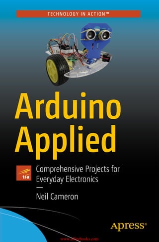
  • 1. TECHNOLOGY IN AC TION™ Arduino Applied Comprehensive Projects for Everyday Electronics — Neil Cameron www.allitebooks.com
  • 2. Arduino Applied Comprehensive Projects for Everyday Electronics Neil Cameron www.allitebooks.com
  • 3. Arduino Applied: Comprehensive Projects for Everyday Electronics ISBN-13 (pbk): 978-1-4842-3959-9 ISBN-13 (electronic): 978-1-4842-3960-5 https://doi.org/10.1007/978-1-4842-3960-5 Library of Congress Control Number: 2018965611 Copyright © 2019 by Neil Cameron This work is subject to copyright. All rights are reserved by the Publisher, whether the whole or part of the material is concerned, specifically the rights of translation, reprinting, reuse of illustrations, recitation, broadcasting, reproduction on microfilms or in any other physical way, and transmission or information storage and retrieval, electronic adaptation, computer software, or by similar or dissimilar methodology now known or hereafter developed. Trademarked names, logos, and images may appear in this book. Rather than use a trademark symbol with every occurrence of a trademarked name, logo, or image we use the names, logos, and images only in an editorial fashion and to the benefit of the trademark owner, with no intention of infringement of the trademark. The use in this publication of trade names, trademarks, service marks, and similar terms, even if they are not identified as such, is not to be taken as an expression of opinion as to whether or not they are subject to proprietary rights. While the advice and information in this book are believed to be true and accurate at the date of publication, neither the authors nor the editors nor the publisher can accept any legal responsibility for any errors or omissions that may be made. The publisher makes no warranty, express or implied, with respect to the material contained herein. Managing Director, Apress Media LLC: Welmoed Spahr Acquisitions Editor: Natalie Pao Development Editor: James Markham Coordinating Editor: Jessica Vakili Cover image designed by Freepik (www.freepik.com) Distributed to the book trade worldwide by Springer Science+Business Media New York, 233 Spring Street, 6th Floor, New York, NY 10013. Phone 1-800-SPRINGER, fax (201) 348-4505, e-mail orders-ny@springer-sbm.com, or visit www.springeronline.com. Apress Media, LLC is a California LLC and the sole member (owner) is Springer Science + Business Media Finance Inc (SSBM Finance Inc). SSBM Finance Inc is a Delaware corporation. For information on translations, please e-mail rights@apress.com, or visit http://www.apress. com/rights-permissions. Apress titles may be purchased in bulk for academic, corporate, or promotional use. eBook versions and licenses are also available for most titles. For more information, reference our Print and eBook Bulk Sales web page at http://www.apress.com/bulk-sales. Any source code or other supplementary material referenced by the author in this book is available to readers on GitHub via the book’s product page, located at www.apress.com/978-1-4842-3959-9. For more detailed information, please visit http://www.apress.com/source-code. Printed on acid-free paper Neil Cameron Edinburgh, UK www.allitebooks.com
  • 4. iii About the Author�������������������������������������������������������������������������������xiii About the Technical Reviewer������������������������������������������������������������xv Preface���������������������������������������������������������������������������������������������xvii Table of Contents Chapter 1: Introduction������������������������������������������������������������������������1 Arduino Uno����������������������������������������������������������������������������������������������������������1 Breadboards����������������������������������������������������������������������������������������������������������3 Arduino IDE Software��������������������������������������������������������������������������������������������4 Arduino IDE Sketch�����������������������������������������������������������������������������������������������5 Run the Blink Sketch���������������������������������������������������������������������������������������������6 Electricity Explained����������������������������������������������������������������������������������������������7 Revise the Blink Sketch����������������������������������������������������������������������������������������8 Pulse Width Modulation��������������������������������������������������������������������������������������12 Opening and Saving Sketches����������������������������������������������������������������������������14 Summary������������������������������������������������������������������������������������������������������������15 Components List�������������������������������������������������������������������������������������������������15 Chapter 2: Switches���������������������������������������������������������������������������17 Tactile Switch������������������������������������������������������������������������������������������������������17 Comparison Operators����������������������������������������������������������������������������������������21 Debouncing a Switch������������������������������������������������������������������������������������������22 Hardware Switch Debounce��������������������������������������������������������������������������������25 www.allitebooks.com
  • 5. iv Ball Switch����������������������������������������������������������������������������������������������������������27 Summary������������������������������������������������������������������������������������������������������������29 Components List�������������������������������������������������������������������������������������������������29 Chapter 3: Sensors�����������������������������������������������������������������������������31 Temperature Sensor��������������������������������������������������������������������������������������������31 Variables�������������������������������������������������������������������������������������������������������������35 Humidity Sensor��������������������������������������������������������������������������������������������������37 Library Installation����������������������������������������������������������������������������������������������39 Library Installation Method 1�������������������������������������������������������������������������39 Library Installation Method 2�������������������������������������������������������������������������39 Library Installation Method 3�������������������������������������������������������������������������40 Light Dependent Resistor������������������������������������������������������������������������������������42 Light Dependent Resistor and Several LEDs�������������������������������������������������������46 Voltage Divider����������������������������������������������������������������������������������������������������48 Ultrasonic Distance Sensor���������������������������������������������������������������������������������50 Speed of Sound���������������������������������������������������������������������������������������������������56 Hall Effect Sensor�����������������������������������������������������������������������������������������������57 Sound Sensor������������������������������������������������������������������������������������������������������61 Infrared Sensor���������������������������������������������������������������������������������������������������64 Infrared Distance Module������������������������������������������������������������������������������������67 Passive Infrared Sensor��������������������������������������������������������������������������������������69 Accelerometer and Gyroscope����������������������������������������������������������������������������72 Summary������������������������������������������������������������������������������������������������������������77 Components List�������������������������������������������������������������������������������������������������78 Table of Contents Table of Contents www.allitebooks.com
  • 6. v Chapter 4: Liquid Crystal Display�������������������������������������������������������79 Contrast Adjustment with PWM��������������������������������������������������������������������������83 Scrolling Text�������������������������������������������������������������������������������������������������������85 LCD with I2C Bus�������������������������������������������������������������������������������������������������87 I2C with Temperature and Pressure Sensor��������������������������������������������������������88 16×4 LCD Cursor Positioning������������������������������������������������������������������������������93 Display Entered Values on LCD���������������������������������������������������������������������������95 LCD Character Set�����������������������������������������������������������������������������������������������96 Additional Characters������������������������������������������������������������������������������������������98 Summary����������������������������������������������������������������������������������������������������������100 Components List�����������������������������������������������������������������������������������������������100 Chapter 5: 7-Segment LED Display���������������������������������������������������101 Basic Schematic�����������������������������������������������������������������������������������������������102 PWM and LED Brightness���������������������������������������������������������������������������������105 Shift Register����������������������������������������������������������������������������������������������������107 Shift Register, PWM, and LED Brightness���������������������������������������������������������113 Alphanumeric Characters���������������������������������������������������������������������������������116 Summary����������������������������������������������������������������������������������������������������������118 Components List�����������������������������������������������������������������������������������������������118 Chapter 6: 4-Digit 7-Segment Display����������������������������������������������119 Functions����������������������������������������������������������������������������������������������������������123 One Shift Register���������������������������������������������������������������������������������������������126 Two Shift Registers�������������������������������������������������������������������������������������������131 Summary����������������������������������������������������������������������������������������������������������135 Components List�����������������������������������������������������������������������������������������������136 Table of Contents Table of Contents
  • 7. vi Chapter 7: 8×8 Dot Matrix Display���������������������������������������������������137 One Shift Register���������������������������������������������������������������������������������������������143 Two Shift Registers�������������������������������������������������������������������������������������������146 Scrolling Text�����������������������������������������������������������������������������������������������������150 Summary����������������������������������������������������������������������������������������������������������156 Components List�����������������������������������������������������������������������������������������������156 Chapter 8: Servo and Stepper Motors����������������������������������������������157 Servo Motors�����������������������������������������������������������������������������������������������������157 Servo Motor and a Potentiometer���������������������������������������������������������������������161 Stepper Motor���������������������������������������������������������������������������������������������������165 Stepper Motor and a Potentiometer������������������������������������������������������������������172 Stepper Motor Gear Ratio���������������������������������������������������������������������������������175 Summary����������������������������������������������������������������������������������������������������������176 Components List�����������������������������������������������������������������������������������������������176 Chapter 9: Rotary Encoder����������������������������������������������������������������177 Rotary Encoder and Stepper Motor�������������������������������������������������������������������182 Summary����������������������������������������������������������������������������������������������������������186 Components List�����������������������������������������������������������������������������������������������187 Chapter 10: Infrared Sensor�������������������������������������������������������������189 Infrared Emitter and Sensor������������������������������������������������������������������������������195 Infrared Emitter and Receiver���������������������������������������������������������������������������197 Summary����������������������������������������������������������������������������������������������������������200 Components List�����������������������������������������������������������������������������������������������201 Chapter 11: Radio Frequency Identification�������������������������������������203 Display Content of MIFARE Classic 1K and 4K��������������������������������������������������205 Mimic RFID and Secure Site�����������������������������������������������������������������������������208 Table of Contents Table of Contents
  • 8. vii Master Card Validation��������������������������������������������������������������������������������������211 Read and Write to Classic 1KB Card�����������������������������������������������������������������213 Summary����������������������������������������������������������������������������������������������������������217 Components List�����������������������������������������������������������������������������������������������217 Chapter 12: SD Card Module�������������������������������������������������������������219 Temperature and Light Intensity Logging���������������������������������������������������������220 Date and Time Logging�������������������������������������������������������������������������������������226 Logging Weather Station Data��������������������������������������������������������������������������228 Increment File Name for Data Logging�������������������������������������������������������������232 Listing Files on an SD Card�������������������������������������������������������������������������������234 Summary����������������������������������������������������������������������������������������������������������236 Components List�����������������������������������������������������������������������������������������������236 Chapter 13: Screen Displays�������������������������������������������������������������237 TFT LCD Screen�������������������������������������������������������������������������������������������������237 Displaying Images from an SD Card�����������������������������������������������������������������242 Screen, Servo Motor, and Ultrasonic Distance Sensor��������������������������������������243 OLED Display�����������������������������������������������������������������������������������������������������249 Touch Screen����������������������������������������������������������������������������������������������������252 Summary����������������������������������������������������������������������������������������������������������258 Components List�����������������������������������������������������������������������������������������������259 Chapter 14: Sensing Colors��������������������������������������������������������������261 Red Green Blue (RGB) LED��������������������������������������������������������������������������������262 565 Color Format����������������������������������������������������������������������������������������������264 Color-Recognition Sensor���������������������������������������������������������������������������������267 Summary����������������������������������������������������������������������������������������������������������275 Components List�����������������������������������������������������������������������������������������������275 Table of Contents Table of Contents
  • 9. viii Chapter 15: Camera��������������������������������������������������������������������������277 Camera Image Capture Setup���������������������������������������������������������������������������281 Capturing Camera Images��������������������������������������������������������������������������������285 Summary����������������������������������������������������������������������������������������������������������288 Components List�����������������������������������������������������������������������������������������������288 Chapter 16: Bluetooth Communication���������������������������������������������289 Bluetooth Terminal HC-05 App��������������������������������������������������������������������������292 ArduDroid App���������������������������������������������������������������������������������������������������295 Message Scrolling with MAX7219 Dot Matrix Module��������������������������������������300 MAX7219 and Bluetooth Terminal HC-05 App���������������������������������������������������302 Message Speed and Potentiometer������������������������������������������������������������������306 MAX7219 and ArduDroid App����������������������������������������������������������������������������307 Summary����������������������������������������������������������������������������������������������������������310 Components List�����������������������������������������������������������������������������������������������310 Chapter 17: Wireless Communication����������������������������������������������311 Transmit or Receive������������������������������������������������������������������������������������������315 Transmit and Receive����������������������������������������������������������������������������������������317 Summary����������������������������������������������������������������������������������������������������������322 Components List�����������������������������������������������������������������������������������������������323 Chapter 18: Build Arduino����������������������������������������������������������������325 ATmega328P Pin Layout�����������������������������������������������������������������������������������326 Building an Arduino�������������������������������������������������������������������������������������������328 Installing the Bootloader�����������������������������������������������������������������������������������332 Summary����������������������������������������������������������������������������������������������������������336 Components List�����������������������������������������������������������������������������������������������337 Table of Contents Table of Contents
  • 10. ix Chapter 19: Global Navigation Satellite System�������������������������������339 GNSS Messages on Serial Monitor�������������������������������������������������������������������339 u-blox u-center�������������������������������������������������������������������������������������������������341 Arduino and GNSS���������������������������������������������������������������������������������������������343 GNSS Data Logging to SD Card�������������������������������������������������������������������������357 GNSS and ST7735 Screen���������������������������������������������������������������������������������360 Displaying GNSS Data���������������������������������������������������������������������������������������368 Summary����������������������������������������������������������������������������������������������������������369 Components List�����������������������������������������������������������������������������������������������369 Chapter 20: Interrupts and Timed Events�����������������������������������������371 Interrupts����������������������������������������������������������������������������������������������������������371 Types of Interrupt����������������������������������������������������������������������������������������������376 Additional Interrupt Pins�����������������������������������������������������������������������������������379 Interrupts and Rotary Encoder��������������������������������������������������������������������������380 Timed Events: delay()���������������������������������������������������������������������������������������384 Timed Events: millis()���������������������������������������������������������������������������������������384 Timed Events: Timer1����������������������������������������������������������������������������������������387 Timer Register Manipulation�����������������������������������������������������������������������������390 Summary����������������������������������������������������������������������������������������������������������395 Components List�����������������������������������������������������������������������������������������������395 Chapter 21: Power Saving����������������������������������������������������������������397 avr/sleep Module����������������������������������������������������������������������������������������������402 LowPower Library���������������������������������������������������������������������������������������������405 Power Down and an Infrared Sensor����������������������������������������������������������������406 Summary����������������������������������������������������������������������������������������������������������410 Components List�����������������������������������������������������������������������������������������������410 Table of Contents Table of Contents
  • 11. x Chapter 22: Sound and Square Waves����������������������������������������������411 Piezo Transducer and Buzzer����������������������������������������������������������������������������416 Musical Notes���������������������������������������������������������������������������������������������������416 Sensor and Sound���������������������������������������������������������������������������������������������420 Generating Square Waves���������������������������������������������������������������������������������425 Square Wave and Servo Motor��������������������������������������������������������������������������431 Summary����������������������������������������������������������������������������������������������������������432 Components List�����������������������������������������������������������������������������������������������432 Chapter 23: DC Motors����������������������������������������������������������������������433 Motor Control Set in the Sketch������������������������������������������������������������������������438 Motor Speed������������������������������������������������������������������������������������������������������441 Motor Control with Infrared Remote Control�����������������������������������������������������444 Motor Control with Wireless Communication����������������������������������������������������445 Motor Control with Accelerometer��������������������������������������������������������������������452 Motor Control with Photoelectric Encoder��������������������������������������������������������457 Summary����������������������������������������������������������������������������������������������������������465 Components List�����������������������������������������������������������������������������������������������465 Chapter 24: Robot Car����������������������������������������������������������������������467 PID Controller����������������������������������������������������������������������������������������������������475 Balancing Robot������������������������������������������������������������������������������������������������481 Determining PID Coefficients����������������������������������������������������������������������������483 Circular Buffer���������������������������������������������������������������������������������������������������485 Quaternion Measurements��������������������������������������������������������������������������������489 Summary����������������������������������������������������������������������������������������������������������496 Components List�����������������������������������������������������������������������������������������������497 Table of Contents Table of Contents
  • 12. xi Chapter 25: Wi-Fi Communication����������������������������������������������������499 NodeMCU ESP8266�������������������������������������������������������������������������������������������499 WeMos D1 Mini�������������������������������������������������������������������������������������������������502 Wi-Fi and Web Server���������������������������������������������������������������������������������������504 Wi-Fi and HTML�������������������������������������������������������������������������������������������������510 Wi-Fi and Internet Access���������������������������������������������������������������������������������519 Summary����������������������������������������������������������������������������������������������������������530 Components List�����������������������������������������������������������������������������������������������531 Appendix: Resistor Banding�������������������������������������������������������������533 Libraries������������������������������������������������������������������������������������������������������������534 Quaternion Measurements��������������������������������������������������������������������������������537 Who’s Who in Electronics����������������������������������������������������������������������������������541 Sources of Electronic Components�������������������������������������������������������������������542 Index�������������������������������������������������������������������������������������������������545 Table of Contents Table of Contents
  • 13. xiii About the Author Neil Cameron was a research scientist in quantitative genetics at Roslin Institute (of “Dolly the sheep” fame) with expertise in data analysis and computer programming. Neil has taught at the University of Edinburgh and Cornell University. He has a deep interest in electronics and “how things work,” with a focus on programming the Arduino and its application on a range of comprehensive projects for everyday electronics, which inspired him to write this book.
  • 14. xv About the Technical Reviewer Fabio Claudio Ferracchiati is a senior consultant and a senior analyst/ developer using Microsoft technologies. He works at BluArancio S.p.A (www.bluarancio.com) as senior analyst/developer and Microsoft Dynamics CRM Specialist. He is a Microsoft Certified Solution Developer for .NET, a Microsoft Certified Application Developer for .NET, a Microsoft Certified Professional, and a prolific author and technical reviewer. Over the past ten years, he’s written articles for Italian and international magazines, and co-authored more than ten books on a variety of computer topics.
  • 15. xvii Preface Microcontrollers are incorporated in car control systems, domestic appliances, office machines, mobile phones, medical implants, remote controls, and the list goes on. The Arduino Uno is a microcontroller board that can be easily programmed and used to build projects. The objective of this book is to provide information to use the Arduino Uno in a range of applications, from blinking an LED to a motion sensor alarm, to route mapping with a mobile GPS system, to uploading information to the Internet. Prior knowledge of electronics is not required, as each topic is described and illustrated with examples using the Arduino Uno. The book covers a comprehensive range of topics. In Chapters 1–3, the Arduino Uno and the Arduino programming environment are set up, and several sensors are described with practical examples to provide the basis for subsequent projects. Information display with the Arduino Uno using liquid crystal, LED, and dot matrix displays are described in Chapters 4–7. Several projects are developed with servo and stepper motors, infrared control, RFID, and SD card data logging in Chapters 8–12. Sensing and displaying color is outlined in Chapters 13–14, and recording images in Chapter 15. Bluetooth, wireless, and Wi-Fi communication systems are described in Chapters 16, 17 and 25, with practical examples of message scrolling, servo motor control, and web-based information display projects, respectively. The Arduino Uno is deconstructed to the microcontroller for use in a mobile GPS system, with timed events and power-saving methods in Chapters 18–21. Electronic sound projects are outlined in Chapter 22. An obstacle-avoiding robot car and a balancing robot are described in Chapters 23 and 24, with the robot car controlled by systems described in earlier chapters.
  • 16. xviii Projects covered in the book include and extend those in Arduino Uno starter kits to increase knowledge of microcontrollers in electronic applications. Many of the projects are practically orientated, such as information displays, GPS tracking, RFID entry systems, motion detector alarms, and robots. Building projects helps you understand how many electronic applications function in everyday life. Examples include flashing numbers on a screen, a scrolling message in the train station, electronic tags on items in a shop or books in the library, a desktop weather station, Bluetooth communication with a mobile phone, digital sound systems, and an obstacle-avoiding robot vacuum cleaner. Each example in the book is accompanied by code and a description of that code, which helps you learn how to program a microcontroller and a computer, which is a highly valuable skill. The Arduino programming language is C, which is widely used. Learning to program an Arduino provides the framework for other computer programming languages. Throughout the book, schematic diagrams were produced with Fritzing software (www.fritzing.org), with an emphasis on maximizing the clarity of component layout and minimizing overlapping connections. The authors of the libraries used in the book are identified in each chapter, with library details covered in the appendix. There are several approaches to structuring sketches, and the approach taken in the book is to declare variables at the start of the sketch, rather than throughout the sketch. All the code used in the book is available to download from github. com/Apress/arduino-applied. The Arduino programming environment and libraries are constantly being updated, so information on the consequences of those updates on the content of the book is also available at github.com/Apress/arduino-applied. Many chapters of the book are stand-alone, so that you can delve into a section of the book rather than having to start from the beginning, while several chapters utilize information from earlier chapters to build a project. You learn how to break down a complex project into smaller Preface Preface
  • 17. xix projects, just as each chapter addresses a different topic, to then be able to build and enhance the initial project. If you bought, or are thinking about buying, an Arduino Uno starter kit that contains a few LEDs, a variety of sensors, with some switches and resistors, then this book is for you. If you want to build electronics projects with a microcontroller, then the comprehensive range of topics covered in the book provides the detailed instructions to get started. Preface Preface
  • 18. 1 © Neil Cameron 2019 N. Cameron, Arduino Applied, https://doi.org/10.1007/978-1-4842-3960-5_1 CHAPTER 1 Introduction The Arduino Uno provides the framework to learn about electronics, and to understand and build electronic devices. The Arduino Uno can monitor an environment with sensors, drive LED message boards, generate sound and light patterns, take and display digital photos, communicate by Bluetooth or wirelessly with other electronic devices, communicate by Wi-­ Fi to the Internet, and record data on the route, speed, and altitude of a trip with GPS. Arduino Uno The Arduino Uno R3 (see Figure 1-1) contains the ATmega328P microcontroller to carry out programmed instructions and memory to store data. The Arduino is powered through a DC input or a USB connection, which is also used to upload instructions and communicate with a computer or laptop. An ATmega16U2 chip manages USB (Universal Serial Bus) to serial communication. The power pins allow 5V (5 volts) or 3.3V and ground (GND) to connect other devices. Pins 0 and 1 are for transmitting and receiving serial data from other devices. Pins 2 to 13 are digital input and output, which input or output 5V for a digital one or 0V for a digital zero. Several output pins vary the time that a pin state is 5V to emulate voltages between 0V and 5V. The analog pins, A0 to A5, measure voltages between 0V and 5V and convert analog signals to digital values (ADC). Pins A4 and A5
  • 19. 2 can also communicate with other devices, as can pins 10 to 13, but using different communication systems, I2C and SPI respectively, than the USB connection. Three LEDs (light-emitting diode) indicate power (ON), transmitting (TX), and receiving (RX), with a fourth LED connected to pin 13. The Reset button is used to restart the microcontroller. The functionality of the Arduino Uno enables a comprehensive range of projects to be developed, which are described throughout the book. Several of the terms—such as ADC, I2C, and SPI—may mean little to you just now, but they are explained in the relevant chapters. Figure 1-1. Arduino Uno Chapter 1 Introduction
  • 20. 3 Breadboards The solderless breadboard contains columns of connected sockets for positioning electronic components to create a circuit and for connecting to the Arduino (see Figure 1-2). The two rows along the length (left to right) of the breadboard are used to connect to power (red) or ground (blue) lines in a circuit. Holes in each short column (green) of the breadboard are connected together, but the columns are not connected, so that two components each with one “leg” in the same green column are connected together. The middle area in the breadboard separates the breadboard into two unconnected halves. Breadboards come in a variety of sizes. Figure 1-2. Breadboard The term breadboard originates from radio amateurs attaching fixing points to a wooden breadboard and then connecting electronic components to the fixing points. For example, Figure 1-3 shows a circuit with an LED, a 100Ω resistor, and a 3V battery. The positive or red terminal of the 3V battery is connected to the long leg of the LED, as the relevant component legs are in the same short column. Likewise, the short leg of the LED is connected to the “top” end of the 100Ω resistor, but not to the “bottom” end of the Chapter 1 Introduction
  • 21. 4 Arduino IDE Software The Arduino IDE (interactive development environment) software is downloaded from www.arduino.cc/en/Main/Software, with the downloaded arduino-version number-windows.exe file saved to the desktop. The .exe file is double-clicked to start the installation. The Arduino IDE program files are stored in C: ➤ Program Files (x86) ➤ Arduino, which includes example sketches located in C: ➤ Program Files (x86) ➤ Arduino ➤ examples. Each example sketch is accompanied by a text file outlining the objective of the sketch, the breadboard layout of the components, and a circuit diagram. The Arduino IDE is used to write, compile, and upload files to the microcontroller. A file containing Arduino code is called a sketch. Within the Arduino IDE, clicking one of the five IDE symbols provides quick access to compile a sketch, to compile and upload a sketch, to open a blank sketch, to open an existing sketch from a list of all sketches, Figure 1-3. LED and resistor circuit resistor due to the separating middle area of the breadboard. To complete the circuit, a black wire connects the negative or black terminal of the 3V battery to the “bottom” end of the resistor. Chapter 1 Introduction
  • 22. 5 and to save the current sketch. The Open an existing sketch option does not scroll the complete list of sketches, so use File ➤ Sketchbook instead. Some useful options from the drop-down menu are given in Table 1-1. Table 1-1. Drop-down Menu Options of the Arduino IDE Options Description File ➤ Open Recent A list of recently accessed sketches File ➤ Examples Arduino IDE built-in sketches Edit ➤ Find Find and replace text in a sketch Sketch ➤ Include Library Arduino and contributed libraries Tools ➤ Serial Monitor Displays serial data to serial monitor Tools ➤ Serial Plotter Graphic display of serial data Tools ➤ Board Description of the microcontroller for example Arduino/Genuino Uno Tools ➤ Port Detail of serial port, for example COM3 Arduino/Genuino Uno File ➤ Open Recent List of recently accessed sketches Arduino IDE Sketch An Arduino IDE sketch consists of three parts: variable definition, the void setup(), and the void loop() functions. The first part includes defining which Arduino pins are connected to sensors, LEDs, or devices, and declaring the values of variables. For example, the int LEDpin = 9 instruction defines a variable, named LEDpin, with the integer value of 9. The void setup() function implements definitions in the first part of the Chapter 1 Introduction
  • 23. 6 sketch and only runs once. For example, the pinMode(LEDpin, OUTPUT) instruction defines the Arduino pin 9 as an output pin, rather than an input pin by default, since LEDpin has the value 9. The void loop() function runs continuously and implements the sketch instructions. For example, a sketch may turn on and off an LED at given times. Declaring variables in the first part of the sketch makes it easier to update the variable once at the start of the sketch, rather than having to check through the sketch and update variables throughout the sketch. Comments are prefaced by //, such as // Set LED to pin 9, and are not implemented by the microcontroller. With a couple of exceptions, all instruction lines end with a semicolon. Run the Blink Sketch Follow these steps to run the blink sketch. 1. Connect the Arduino to a computer or laptop with the USB-to-serial cable. 2. In Arduino IDE, select File ➤ Examples ➤ 01. Basics ➤ Blink. 3. Click the Compile and Upload, , button. The built-in LED on the Arduino will now flash every second. Welcome to Arduino ! The error message indicates that the serial port should be updated. Select Tools ➤ Port and choose the appropriate port (for example, COM3 or COM4) for the Arduino. Go to step 3. The error message indicates that the description of the microcontroller should be updated. Select Tools ➤ Board and choose the relevant board (for example, Arduino/ Genuino Uno). Go to step 3. Chapter 1 Introduction
  • 24. 7 Electricity Explained An understanding of electricity is helpful before progressing further. All materials are made of atoms, which consist of protons, neutrons, and electrons. Electrons have a negative charge and can move from one atom to another. Electricity is the movement of electrons between atoms, or rather the flow of an electrical charge. A simple example of an electrical charge is rubbing a cloth over an inflated balloon. Electrons are rubbed off the cloth and onto the balloon, making the balloon negatively charged. If the balloon is now placed near an object, then the balloon “sticks” to the object. The negative charge of the balloon repels the negatively charged electrons of the object, leaving an excess of positive charge next to the balloon. Since positive and negative charges attract, then the balloon is attracted to the object. The effect of moving an electric charge from one object to another has been known for centuries. More than two-and-a-half-thousand years ago, the Greeks knew that rubbed amber, which is fossilized tree resin, could attract light objects, such as hair. The word electric derives from the Greek word for amber, elektron. A discharging battery is a source of electrons, and the electrons move from the negative terminal, the anode, to the positive terminal, the cathode. The words anode and cathode are derived from the Greek words anodos and kathodos, so cathode is abbreviated as K. Although electrons flow from anode to cathode, the conventional current flows from cathode to anode, or from positive to negative. Describing electricity uses the terms charge, voltage, current, and resistance. The analogy of water flowing from a reservoir through a pipe can be used to envisage some of the electrical terms (see Table 1-2). Chapter 1 Introduction
  • 25. 8 The relationship between voltage (V), current (I), and resistance (R) is V = I × R, which is Ohm’s law. Charge is measured in amp-hours (Ah), which is the charge transferred by a current of one amp for one hour. The length of time that a battery, such as a nickel metal hydride (NiMH) AA battery with a charge of 2400mAh, can supply a given current depends on the size of the current. For example, with discharge rates of 2400, 4800, or 7200mAh, the battery would last 60, 30, or 20 minutes. Electrical power, measured in watts (W), is the rate that energy is transferred in unit time, equal to the product of voltage and current. Revise the Blink Sketch The blink sketch can be changed to make a separate LED blink rather than the LED on the Arduino. The Arduino supplies a regulated 5V output from the pin marked 5V, but a resistor is required to ensure that the current does not exceed the LED’s maximum permitted current of 20mA. Without the resistor, the high current would damage the LED. Using Ohm’s law, which states voltage equals the product of current and resistance, or V = I × R, the value of the resistor (R) can be determined, Table 1-2. Electrical Parameter and Water Analogy Electrical Parameter Water Analogy Electrical charge (coulombs, C) Amount of water in the reservoir Voltage (volts, V) Water pressure at the reservoir end of the pipe Current (amperes or amps, A) Rate of water flow Resistance (ohms, Ω) Inverse of pipe width (narrow pipe ⇒ high resistance) Chapter 1 Introduction
  • 26. 9 given the known voltage (V) and current (I). The forward voltage drop across the LED is 2V, which is the minimum voltage required to turn on the LED. With a 5V output from the Arduino, there is 3V = 5V – 2V across the resistor (see Figure 1-4). If the current through the resistor and the LED is to be at most 20mA, then from Ohm’s law, the resistor value (R = V/I) = 3/0.02 = 150Ω, which is equal to the voltage across the resistor divided by the current through the resistor. A resistor of at least 150Ω would protect the LED from an excessively high current and the widely available 220Ω resistor can be used. Resistors are color-coded (see Appendix) to identify the resistance, but checking the resistance with a multimeter is straightforward. Resistors are connected either way around in a circuit. The power through the resistor should be checked to ensure that it is not greater than the maximum value for the resistor. In the example, the maximum power rating of the resistor is 250mW. With 3V across the resistor and 20mA maximum current, then power = V × I = 60mW, which is well below the maximum value. An LED is a diode, which allows current to pass in one direction only. The long leg of the LED is the anode and the flat side of the LED is on the cathode side. LEDs contain semiconductor material, which determines the wavelength of light emitted: red, green, blue, or yellow. The forward voltage drop of red, yellow, and green LEDs is lower than for blue and white LEDs: 2.0V and 2.9V, respectively. If an LED and resistor were connected as in the left-hand side of Figure 1-4, then the LED would stay on continuously. If the LED was connected to an Arduino pin, then changing the pin status from 5V (HIGH) to 0V (LOW) to HIGH repeatedly would turn on and off the LED. The revised circuit in the right-hand side of Figure 1-4 has the LED anode connected to pin 11 of the Arduino. Switching the LED on and off is a digital or binary operation, 0 or 1, requiring a digitalWrite instruction to pin 11 to enable or disable a power supply to the LED. Connections for the two examples in Figure 1-4 are given in Table 1-3. Chapter 1 Introduction
  • 27. 10 Figure 1-4. Blink an LED Table 1-3. Connections for LED Component Figure 1-4 left-hand side Figure 1-4 right-hand side Connect to and to Connect to and to LED long leg Arduino 5V Arduino pin 11 LED short leg 220Ω resistor Arduino GND 220Ω resistor Arduino GND The revised blink sketch is shown in Listing 1-1. The LED is connected to Arduino pin 11. In the void setup() function, the Arduino pin defined by the LEDpin variable is defined as an OUTPUT pin, rather than an INPUT pin that would be used for input, such as measuring a voltage. In the void loop() function, the state of Arduino pin 11 is repeatedly changed from HIGH to LOW and LOW to HIGH at one-second intervals, which corresponds to changing the output voltage on the pin from 5V to 0V, and so the LED turns on and off. Chapter 1 Introduction
  • 28. 11 Listing 1-1. Sketch to Blink an LED int LEDpin = 11;              //defineLEDpinwithintegervalue11 void setup()                  // setup function runs once {   pinMode(LEDpin, OUTPUT);    // define LEDpin as output } void loop()                   // loop function runs continuously {   digitalWrite(LEDpin, HIGH);   //setpinstateHIGHtoturnLEDon   delay(1000);                 // wait for a second = 1000ms   digitalWrite(LEDpin, LOW);  // set pin state LOW to turn LED off   delay(1000); } Instructions within the void setup() and void loop() functions are included in curly brackets, indicating the start and end of the function, with the instructions indented to make the sketch easier to interpret. Sketches must include both the void setup() and void loop() functions, even if a function contains no instructions. Comments are useful to interpret a sketch. A comment is text after the // characters. Several lines of comments can be included when bracketed by /* and */, such as /* this is the first line of comment this is the second line of comment this is the last line of comment */ The schematic format has red and black wires for VCC (positive voltage) and GND (ground), with yellow, blue, or green wires connecting electronic components to Arduino pins. In general, green is used for an input signal and yellow for an Arduino output signal. Chapter 1 Introduction
  • 29. 12 Pulse Width Modulation Several Arduino pins, those marked with ~ support Pulse Width Modulation (PWM), which replaces a constant HIGH signal with a square wave, pulsing HIGH and LOW, and the pulse width can be modified (see Figure 1-5). The impact of PWM on an LED is to change the perceived continuous brightness of an LED, even though the LED is being turned on and off repeatedly. PWM is also used to control the speed of motors and to generate sound. The PWM frequency on Arduino pins 5 and 6 is 976 cycles per second (Hertz or Hz), so the interval between pulses, indicated by the green dotted lines in Figure 1-5, is 1.024ms. Most people cannot detect flicker between images displayed above 400Hz, so an LED turned on and off at 976Hz appears to be constantly on. The square wave is generated by the analogWrite(pin, value) instruction with a duty cycle of (value/255), so a 0% or 100% duty cycle corresponds to a value of 0 or 255. For example, in Figure 1-5, with a 5V supply, the PWM duty cycles of 0%, 25%, 50%, 75%, and 100% can be broadly thought of as supplying average voltages of 0V, 1.25V, 2.5V, 3.75V, and 5V, respectively. PWM is one mechanism for supplying “analog” signals from a “digital” 0V or 5V signal, and it is used in many projects throughout the book. Chapter 1 Introduction
  • 30. 13 The sketch (see Listing 1-2) uses PWM to change the brightness of an LED with the rate of change controlled by the increm and time variables. Listing 1-2. LED Brightness and PWM int LEDpin = 11;            // define LED pin int bright = 0;              // initial value for LED brightness int increm = 5;              //incrementalchangeinPWMfrequency int time = 25;                //definetimeperiodbetweenchanges void setup()                // setup function runs once {   pinMode(LEDpin, OUTPUT);  // LED pin as output } Figure 1-5. Pulse width modulation Chapter 1 Introduction
  • 31. 14 void loop()                     // loop function runs continuously {   analogWrite(LEDpin, bright);  // set LED brightness with PWM   delay(time);                  // wait for the time period   bright = bright + increm;     // increment LED brightness   if(bright =0 || bright = 255) increm = - increm; }                      // reverse increment when brightness = 0 or 255 The symbols || denote OR, so the if(bright = 0 || bright = 255) increm = -increm instruction is equivalent to “if the bright variable is less than or equal to zero, or greater than or equal to 255, then change the sign of the increm variable.” The OR instruction reverses the increasing brightness to decreasing brightness, and vice versa. Opening and Saving Sketches To open a saved sketch, within the Arduino IDE, select File ➤ Open. Choose the folder name containing the sketch, click Open, select the sketch, and click Open. Alternatively, select File ➤ Open Recent. A list of recently opened sketches is displayed, then click the required sketch. The default location for saving sketches is determined by selecting File ➤ Preferences in the Arduino IDE. To save a sketch, select File ➤ Save As, which opens the default sketches folder, then choose a file name for the sketch and click Save. The file name must not contain spaces, so use an underscore instead, such as in file_name. When a sketch is saved, a folder is automatically generated to contain the sketch. When a sketch has been edited in the Arduino IDE, a § symbol follows the sketch name to indicate that changes have been made since the sketch was last saved. To save an existing sketch, select File ➤ Save. If changes have been made to a sketch, then after saving the sketch, the § symbol disappears. Chapter 1 Introduction
  • 32. 15 Summary The Arduino Uno and the Arduino IDE programming environment were described. An introduction to programming the Arduino enabled a sketch to control an LED turning on and off. The blink sketch was changed to vary the brightness of the LED using Pulse Width Modulation. A summary of electricity, including Ohm’s Law, helped you understand how an LED functions and that an LED requires a resistor to reduce the current. Components List • Arduino Uno and breadboard • LED • Resistor: 220Ω Chapter 1 Introduction
  • 33. 17 © Neil Cameron 2019 N. Cameron, Arduino Applied, https://doi.org/10.1007/978-1-4842-3960-5_2 CHAPTER 2 Switches Switches are used to turn devices on or off, such as a room light or an electrical appliance, and when sending a signal, such as pressing a particular key on a keyboard. Switches can also be used to control devices; a device is on when the switch is initially pressed or while the switch is pressed. The metal contacts of switches can bounce when the switch is pressed, which could repeatedly turn a device on and off again. Switch bouncing can be controlled using software or by hardware, which is called debouncing a switch. Tactile Switch A switch can be connected to an Arduino pin to turn an LED on or off. When the switch is closed, the digital pin is connected to 5V and the pin state is HIGH. When the switch is open, the 10kΩ pull-down resistor permits a small current to flow between the digital pin and GND, so the pin state is pulled down to LOW (see Figure 2-1).
  • 34. 18 If the switch and resistor are reversed, relative to the digital pin, then when the switch is open, the digital pin is connected to 5V, through the 10kΩ pull-up resistor, and the pin state is HIGH. Use of a pull-down or a pull-up resistor depends on whether the pin state is to be LOW or HIGH when the switch is open. If a pull-down or pull-up resistor was not included, then when the switch is open the digital pin would not be connected to GND or to 5V, so the pin state would be undefined. Incorporation of a switch with the pull-down resistor is shown in Figure 2-­2. Figure 2-1. Pull-down resistor Chapter 2 Switches
  • 35. 19 Figure 2-2. LED switch with pull-down resistor Table 2-1. Connections for LED Switch with Pull-Down Resistor Component Connect to and to Switch left Arduino 5V Switch right Arduino pin 8 Switch right 10kΩ resistor Arduino GND LED long leg Arduino pin 4 LED short leg 220Ω resistor Arduino GND The switch module consists of two pairs of connected pins, with the switch pins close together on the underside of the switch. Connections for Figure 2-2 are given in Table 2-1. Chapter 2 Switches
  • 36. 20 Listing 2-1 turns an LED on while the switch is pressed and off while the switch is not pressed. The digitalRead(pin number) instruction reads the state of the pin, HIGH or LOW. Listing 2-1. LED Switch int switchPin = 8;                  // define switch pin int LEDpin = 4;                     // define LED pin int reading;                        // define reading as integer void setup() {   pinMode(LEDpin, OUTPUT);          // LED pin as output } void loop() {   reading = digitalRead(switchPin); // read switch pin   digitalWrite(LEDpin, reading);    // turn LED on if switch is HIGH }                                    // turn LED off if switch is LOW It would be more useful to turn the LED on or off only when the switch is pressed (see Listing 2-2). The states of the switch and LED are stored as variables, switchState and LEDState, respectively. When the switch is initially pressed, the switch state changes from LOW to HIGH and the state of the LED is updated from either LOW (off) to HIGH (on) or from HIGH to LOW. The switchState variable is also updated when the switch is initially pressed, but if the switch is continuously pressed, then the switch state does not change. Releasing the switch changes the switch state from HIGH to LOW and the switchState variable is updated, but there is no change in the LED state. The void loop() function continues to read the switch pin. Chapter 2 Switches
  • 37. 21 Listing 2-2. LED Switch Only When Pressed int switchPin = 8;                  // define switch pin int LEDpin = 4;                     // define LED pin int reading;                        // define reading as an integer int switchState = LOW;              // set switch state to LOW int LEDState = LOW;                 // set LED state to LOW void setup() {   pinMode(LEDpin, OUTPUT);          // LED pin as output } void loop() {   reading = digitalRead(switchPin); // read switch pin   if(reading != switchState)        // if switch state has changed   {                                 // if switch pressed, change LED state     if(reading == HIGH switchState == LOW) LEDState = !LEDState;     digitalWrite(LEDpin, LEDState); // turn LED on or off     switchState = reading;          // update switch state   } } Comparison Operators A logical AND is indicated with the symbol, such as if(XY A==HIGH), which indicates that if X is greater than Y and A is equal to HIGH, then the outcome is true. A logical OR is indicated with the || symbol, such as if(XY || A==HIGH), which indicates that if X is greater than Y or A is equal to HIGH, then the outcome is true. Chapter 2 Switches
  • 38. 22 The double equals sign (==) denotes “is equal to” in a comparison, as in if(reading == HIGH), which means “if reading is equal to HIGH” . != denotes “is not equal to” in a comparison as in if(reading != switchState), which means “if reading is not equal to switchState” . The exclamation mark ! denotes “the opposite value” , as in LEDState = !LEDState, which means “change LEDstate to its opposite value” , which is from HIGH to LOW or LOW to HIGH. The equivalent of X = X + 1 is X++ and similarly, X-- is equivalent to X = X - 1. The calculation y%x is y modulus x, or the remainder when integer y is divided by integer x. Debouncing a Switch When a switch is pressed, the springy nature of the metal used in the contact points can cause the contact points to touch several times; in other words, to bounce, before making a permanent contact. The Arduino clock speed of 16MHz equates to 16 million operations per second, so a bouncing switch contact appears to the microcontroller as having closed and opened several times when the switch is pressed. For example, when an LED is controlled by a switch, sometimes the LED does not turn on or off when the switch is pressed. The switch can be debounced by two software methods or by a hardware solution. One software method initiates a delay, following a change in the switch state, and then rereads the switch state after the delay, defined by the delay(milliseconds) instruction. If the delay is too short, then the switch may still be bouncing at the end of the delay. The void loop() function in Listing 2-3 includes the debounce delay, rereads the switch pin and compares the new switch state with the switch state read before the delay. In Listing 2-3, the new instructions compared to Listing 2-2 are highlighted in bold. Chapter 2 Switches
  • 39. 23 Listing 2-3. LED Switch with Debounce Time void loop() {   reading = digitalRead(switchPin);  // read switch pin   if(reading != switchState)         // if state of switch has changed   {     delay(50);                         // debounce time of 50ms     reading = digitalRead(switchPin);  // read switch pin again     if(reading != switchState)         // compare switch state again     {       if (reading == HIGH switchState == LOW) LEDState =!LEDState;        digitalWrite(LEDpin, LEDState);        switchState = reading;     }   } } A second software method is to continue delaying until there is no longer a change in the switch state at the end of the delay or debounce time. The debounce time is essentially the time that the switch must be held in a constant state before the LED is turned on or off. The state of the switch has to be stored at three times: before the switch was pressed (oldSwitch), when the switch was pressed during the debounce time (switchState) and when the switch was last pressed (reading). The millis() function counts the number of milliseconds that the sketch has been running and is used to store the time when the switch was pressed. The state of the switch is continuously read, until the switch state is the same for longer than the debounce time, at which time the LED can be turned on or off. The number of milliseconds may be greater than the upper limit of an integer number (215 –1)ms or 33 seconds, so the time variable is defined as an unsigned long with maximum value of (232 –1)ms or 50 days. Chapter 2 Switches
  • 40. 24 In Listing 2-4, lastSwitch refers to the time the switch was last pressed during the debounce time and the changes relative to the non-debounced sketch, Listing 2-2, are highlighted in bold. Listing 2-4. Debounced LED Switch with Continued Delay int switchPin = 8;             // define switch pin int LEDpin = 4;                // define LED pin int reading;                   // define reading as an integer int switchState = LOW;         // set switch state to LOW int LEDState = LOW;            // set LED state to LOW unsigned long switchTime;      // define time as unsigned long int lastSwitch = LOW;          // set last switch press in debounce time int debounceTime = 50;         // define debounce time in ms void setup() {   pinMode(LEDpin, OUTPUT);     // LED pin as output } void loop() {   reading = digitalRead(switchPin);  // read switch pin   if(reading != lastSwitch)    // if reading different from last reading   {     switchTime = millis();     // time switch state change in debounce time     lastSwitch  = reading;     // update last switch state   }                            // is switch state the same for required time   if((millis() – switchTime) debounceTime)   { Chapter 2 Switches
  • 41. 25     if(reading !=switchState)     {        if (reading == HIGH switchState == LOW) LEDState =!LEDState;       digitalWrite(LEDpin, LEDState);       switchState = reading;     }   } } When the outcome of an if() instruction cannot be included on the same line as the if() instruction, then the outcome of the if() instruction is contained in curly brackets, just as with the void loop() function. Indenting of instructions within an if() instruction makes the sketch easier to interpret. Hardware Switch Debounce The hardware solution is to include a capacitor across the switch (see Figure 2-3). The capacitor charges while the switch is not pressed. When the switch is pressed, the capacitor discharges and the switch signal to the Arduino is HIGH. While the switch bounces, the capacitor maintains the switch signal at HIGH. With the hardware solution, there is no need for the software debouncing sketch. One resistor-­ capacitor combination is a 10kΩ pull- down resistor and 10μF capacitor. Chapter 2 Switches
  • 42. 26 The rate, RC, at which a capacitor charges or discharges depends on the resistance (R) of the resistor and the capacitance (C) of the capacitor. The voltage across the capacitor after t seconds of charging is V(1 − e−t/RC ), where V is the supply voltage, and after t seconds of discharging the voltage across the capacitor is V(e−t/RC ). The higher the RC value, the longer the debounce delay. After the initial switch press and the capacitor discharge, the capacitor has recharged to 50% of capacity and the switch signal is again HIGH after a debounce delay of RC × ln(2) seconds. The debounce delay time can be expressed as 0.693 × RC or RC/1.44 seconds. With the resistor-capacitor combination of a 10kΩ resistor and a 10μF capacitor, the debounce delay is 69ms. There are many resistor-­ capacitor combinations that achieve a given debounce delay lasting RC × ln(2) seconds, but a large resistor should be used to minimize the current through the resistor. Figure 2-3. LED switch and capacitor Chapter 2 Switches
  • 43. 27 Electrolytic capacitors are polarized and the anode must be at a higher voltage than the cathode. The cathode has a “–” marking and a colored strip on the side of the capacitor. The long leg of an electrolytic capacitor is the anode or positive leg (see Table 2-2). Ball Switch A ball switch contains a metallic ball that joins two contact points whenever the switch reaches a certain angle, which can be about 70°, and the ball rolls onto the contact points. A tilt switch is similar to a ball switch, except that a drop of mercury rolls to join the contact points rather than a ball. The layout of the ball switch circuit (see Figure 2-4) is identical to the tactile switch circuit (see Figure 2-2), but the sketch (see Listing 2-5) contains an if else instruction to turn the LED on or off. The if else instruction is more efficient than two if() instructions and is used when there is more than one condition, each with a different outcome. In the ball switch sketch, if the reading is LOW, then the LED is turned on; otherwise, the LED is turned off. Table 2-2. Connections for Figure 2-3 Component Connect to and to Switch left Arduino 5V Switch right Arduino pin 8 Switch right 10kΩ resistor Arduino GND Capacitor negative Switch right Capacitor positive Switch left LED long leg Arduino pin 4 LED short leg 220Ω resistor Arduino GND Chapter 2 Switches