Build Your Own Antenna Tuning Unit (ATU
•
0 gostou•106 visualizações

An antenna tuning unit (ATU) can help improve shortwave radio reception by matching the impedance of a longwire antenna to the 50 ohm impedance of the radio receiver. The ATU transforms the varying impedance of the longwire, which may range from a few to thousands of ohms depending on the frequency, to the 50 ohms expected by the receiver. This allows for more efficient energy transfer between the antenna and radio. The ATU uses a coil with multiple tapping points and two variable capacitors to tune the antenna and receiver sides of the circuit to the same frequency. The "Receiver" control on the ATU tunes the capacitor that matches the impedance to the receiver, while the "
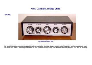
![straightforward to construct and uses simple parts that are quite easy to obtain. The ATU shown above is of my own construction
and is used with a Lowe HF-150 receiver.
Typical Aerial Installation
AERIALS [or ANTENNAS]
AERIAL n. & adj. > n. a metal rod, wire or other structure by which signals are transmitted or received as part of a radio or television
transmission or receiving system. > adj. 1. by or from or involving aircraft (aerial navigation; aerial photography). > 2 a existing,
moving or happening in the air. b of or in the atmosphere, atmospheric. 3 a thin as air, ethereal. b immaterial, imaginary. c of air,
gaseous
For the purpose of this page we'll choose the noun, I think. So the aerial can be:
A Random Length Of Wire Strung As High As Possible
OR -
A Carefully Designed Structure Whereby The Element (Or Elements) Is (Are) Tuned To Resonate At The Required Operating
Wavelength (Frequency) Of The Station Or Waveband Being Received
(What??)
The advantage of a long random wire aerial to a listener is that it is easy to install in a loft or around a garden. Many Short Wave
Listeners' (SWL's) aerials consist of such a long end fed wire of a random length perhaps between 10 and 50 meters, i.e. not cut to
resonate at a specific wavelength. The disadvantage is that it is not tuned to a specific wavelength and therfore may not be
particularly efficient at gathering the signals from a desired station. This is because a random wire aerial system will not present an
even impedance* to the input of the radio receiver. This should generally be around 50 Ohms.
[* Impedance is the resistance to the flow of an alternating current (AC) - in this case a radio wave]
The impedance of a random wire aerial could swing from a few Ohms up to several thousand Ohms depending on what frequency is
being used. This will present a serious mis-match to the receiver, which would prefer to 'see' a nice constant 50 Ohm load. This](data:image/gif;base64,R0lGODlhAQABAIAAAAAAAP///yH5BAEAAAAALAAAAAABAAEAAAIBRAA7)
Recomendados
Mais conteúdo relacionado
Semelhante a Build Your Own Antenna Tuning Unit (ATU
Semelhante a Build Your Own Antenna Tuning Unit (ATU (20)
Mais de ivan ion
Mais de ivan ion (20)
Último
Último (20)
Build Your Own Antenna Tuning Unit (ATU
- 1. . ATUs - ANTENNA TUNING UNITS THE ATU An Antenna Tuning Unit For good Short Wave reception long aerial really is required to dig those distant stations out of the ether. To effectively couple such an aerial to a radio a matching unit called an ATU (Antenna Tuning Unit) can often be extremely helpful. An ATU is relatively
- 2. straightforward to construct and uses simple parts that are quite easy to obtain. The ATU shown above is of my own construction and is used with a Lowe HF-150 receiver. Typical Aerial Installation AERIALS [or ANTENNAS] AERIAL n. & adj. > n. a metal rod, wire or other structure by which signals are transmitted or received as part of a radio or television transmission or receiving system. > adj. 1. by or from or involving aircraft (aerial navigation; aerial photography). > 2 a existing, moving or happening in the air. b of or in the atmosphere, atmospheric. 3 a thin as air, ethereal. b immaterial, imaginary. c of air, gaseous For the purpose of this page we'll choose the noun, I think. So the aerial can be: A Random Length Of Wire Strung As High As Possible OR - A Carefully Designed Structure Whereby The Element (Or Elements) Is (Are) Tuned To Resonate At The Required Operating Wavelength (Frequency) Of The Station Or Waveband Being Received (What??) The advantage of a long random wire aerial to a listener is that it is easy to install in a loft or around a garden. Many Short Wave Listeners' (SWL's) aerials consist of such a long end fed wire of a random length perhaps between 10 and 50 meters, i.e. not cut to resonate at a specific wavelength. The disadvantage is that it is not tuned to a specific wavelength and therfore may not be particularly efficient at gathering the signals from a desired station. This is because a random wire aerial system will not present an even impedance* to the input of the radio receiver. This should generally be around 50 Ohms. [* Impedance is the resistance to the flow of an alternating current (AC) - in this case a radio wave] The impedance of a random wire aerial could swing from a few Ohms up to several thousand Ohms depending on what frequency is being used. This will present a serious mis-match to the receiver, which would prefer to 'see' a nice constant 50 Ohm load. This
- 3. mismatch of impedance between aerial and radio can detrimentally effect the amount of signal transferred from the aerial to the radio, and therfore weaken reception of stations at some wavelengths. An Antenna Tuning Unit (ATU) can help match the impedance of the aerial to the 50 Ohm impedance required by the radio. Once the impedance of the aerial matches the impedance at the input of the radio (after being tuned by the ATU) the greater the chance of the RF energy being effectively transferred. Using an ATU will not always improve reception. If, by pure chance, the random wire aerial presents a 50 Ohm impedance to the radio on, say, the 41 meter band then no further improvement in signal strength will be obtained. But then if the radio is tuned to the 25 meter band, for instance, the aerial may have a 500 Ohm impedance and on this band the ATU will help to transfer more signal and improve reception. WAVELENGTHS AND FREQUENCIES This is the mathematical formula to calculate the wavelength of a particular frequency: V/F = wavelength E.G: V/F = 300,000,000/1,875,000Hz = 300/1.875MHz = 160m The velocity of a radio wave when travelling through space is the same as the spped of light i.e. 300,000,000 meters per second (186,000 miles per second). V = Velocity, F = Frequency in Hz. The result of the calculation is the wavelength in meters. Once the wavelength of the radio wave is known, the relationship with the length of the aerial can be determined. An aerial that is 1/4 wavelength or an odd multiple of 1/4 wavelengths e.g. 5/8th or 7/8th wavelength, the impedance presented to the receiver will be quite low. If the aerial is a full or half wavelength long then the impedance will be much higher. LOWE, JOHN WILSON AND THE SIX BAND SAGGER Have a little look at the bottom of the LOWEHF-150 page since it includes an interesting article by John Wilson, formerly of Lowe Electronics, about aerials, specifically the "SixBandSagger". ATUs AND FILTERING The ATU acts as an Impedance Matching Transformer with the ability to accept a wide range of input impedances and match them to
- 4. the 50ohms that is required by the receiver. It also has the bonus of providing an certain amount of filtering, which can help overcome receiver overloading, by letting through the required frequency while attenuating the higher and lower frequencies. There are two types of ATU circuits described further down this page, the Pi type and the T type. The T type is particularly effective as a 'high pass' filter, and is very useful for filtering out interference on Short Wave caused by high power Medium Wave transmitters that can overload a short wave radio. The graph below shows the effect that can be acheived: The solid line shows the filtering effect of an ATU at shortwave frequencies, while the broken line shows the filtering performance at medium wave frequencies MAKE YOUR OWN ATU The circuit diagram below shows the circuit for a typical Pi type ATU which seems to be a popular arrange ment for many ATUs. I have built ATUs using this Pi arrangement and although they work quite well and are certainly a useful improvement over no ATU at all, I have found in my own experience that the 'T' arrangement in the next circuit works even better, matching more easily over a wide range of frequencies and also seemingly offering improved filtering in my own circumstances. Each aerial arrangement is different and you may find that this circuit performs best of all in your circumstances:
- 5. Pi type circuit - Very popular for many ATUs Below is the circuit diagram for my preferred choice of a T type circuit which includes a variable attenuator and which could not be simpler to construct. This circuit, with the coil described, covers from 500kHz medium wave to 30MHz short wave. Tuning capacitor VC1 is adjusted to match the aerial side while tuning capacitor VC2 is adjusted to match the receiver side. This circuit is often referred to as a TRANSMATCH, particularly in the USA.
- 6. T type circuit, which I have found to be more effective than the Pi type at my listening post, possibly because this design acts as a 'high pass' filter, and is therefore very useful for filtering out interference to short wave reception caused by high power medium wave transmitters that can overload the short wave radio All that is needed is: 1 Self wound coil with 12 tapping points. See below 1 Reel of 22 s.w.g enamelled copper wire for coil 1 Coil former, eg the inside of a fax roll (30 mm diam approx) 1 12 way switch to select tapping pints on coil 2 500pF tuning capacitors (200pF or 365pF can also be used) 1 1 k ohm linear potentiometer for attenuator 2 Red terminal posts 2 Green terminal posts
- 7. 1 Coaxial socket, e.g. 3.5mm jack (as used here) or SO239 1 Case 150 x 100 x 60 mm + with rubber feet SOURCES FOR TUNING CAPACITORS Old broken radio sets - but don't smash a nice one up for the sake of a capacitor! Old radio sets, especially the old 'valved' wirelesses are very interesting and often sound superb and could be quite rare. COIL WINDING DETAILS The coils that I have made for my ATUs have been wound around formers made from the plasic tube found inside a typical fax roll. This can be cut to a suitable length to fit inside the enclosure, in this case 150mm long with a 30mm diameter. If a plastic fax roll is not available then a strong cardboard tube could be used instead. Two small holes can be drilled at each end of the tube to feed the start and finish portions of the 22 swg wire through in order to secure it. Then wind the required number of turns, putting a tight twist in the wire at each tapping point, taking care to scrape off the enamel so that the connecting wire can be soldered into place. Alternatively, as I did in my first coil, I inserted printed circuit board (PCB) terminal pins into the tube to secure the wire to at the start and finish points of the coil and at each tapping point, as you can see in the photograph below. This involved drilling a hole in the soft plasic of the tube slightly smaller than the PCB pin and forcing the first pin in for a tight fit. The enamel must be scraped of the wire, wrapped arount the pin with a single turn and then soldered in place - quickly to avoid melting the plastc! Then the first turn of the coil is made, another hole drilled and pin inserted and wire scraped clean of enamel and soldered to the pin. Proceed until all the turns and tapping points have been made according to the diagram. The diagram below shows the number of turns between each tapping point:
- 8. Once the coil is complete the tapping points can be wired to the 12 way switch by using short lengths of hook-up wire (e.g. 7/0.2mm pvc covered), being careful to wire the into the circuit exactly as in the diagram.
- 9. The Mk1 ATU using the T type circuit
- 10. The rear panel of the Mk1 ATU showing the aerial input and output terminal posts. A 3.5mm jack socket is also included as an alternative output socket for convenient connection to a portable radio via a length of flexible 50 ohm coaxial cable
- 11. Internal view of the Mk 1 Antenna Tuning Unit showing the coil and its 12 tapping points, the range switch and two space-saving Jackson type solid dielectric tuning capacitors. The potentiometer that forms the variable attenuator is hidden from view by the range switch. The Mark 2 Aerial Tuning Unit
- 12. The Mark 2 Antenna Tuning Unit The Mark 1 ATU described above was initially made using the Pi match circuit and when I made this, the Mark2, I used the T match circuit design and when I found that it worked even better I modified the Mark 1 to also use the T match circuit layout. The Mark 1 is used for a portable radio and therefore is more compact, the Mark 2 is used for the HF-150 so can be a bit larger. It is housed in an aluminium case and uses the larger air-spaced tuning capacitors and also has SO239 sockets are fitted for the input and output. The coil is larger too, using the same former made from the centre of a fax roll but longer at 220mm to accommodate additional windings to enable coverage of long wave frequencies. An additional switch is also included to give plenty of adjustment while including the long wave range.
- 13. The circuit diagram showing the coil and the 12 way switch to adjust the Short Wave ranges and the additional 3 way switch to change to Medium Wave and Long Wave coverage*. The attenuator is simply a 1k ohm potentiometer. * Position 1 is Long Wave; 2 Medium Wave; 3 Short Wave ranges - adjusted with 12 way switch Tuning Capacitors: In these circuits, as is the general rule of thumb with radio projects, the moving vanes of tuning capacitors - and therefore the spindles/shafts - are connected to the earthy side of the circuit. Ensuring that the moving vanes are connected to the earthy side minimises 'hand capacitance' effects when touching the adjustment knobs. The fixed vanes are therefore connected to the 'hot' (top) side of the circuit. You will have to determine which terminals on your particular capacitor are connected to the fixed vanes and which are connected to the moving vanes. It should be able to determine this visually from the physical construction of your particular component, but if you are unsure always use the continuity tester function of your multimeter. With dual gang variable capacitors with smaller values per gang, it may be desirable to connect the two fixed sets of vanes together in parallel to increase maximum capacitance. For many metal framed air-spaced variable capacitors the moving vanes will effectively be connected together via the brass spindle to the main frame of the capacitor body. The fixed vanes and their associated terminals will be isolated from the metal frame by ceramic, paxolin, or similar, insulators. PARTS REQUIRED 1 Self wound coil with 13 tapping points
- 14. 1 Reel of 22 swg enamelled copper wire 1 Reel of 30 swg enamelled copper wire (for longwave part) 1 Coil Former 220mm long & approx 30mm diameter 1 12 way switch 1 3 way switch 2 500pF tuning capacitors (200pF or 365pF can also be used) 1 1 k ohm linear potentiometer 2 Red Terminal posts 2 Green terminal posts 2 SO239 sockets 1 Aluminium case 220 x 130 x 65 mm + rubber feet SOURCES FOR TUNING CAPACITORS Old broken radio sets - but don't smash a nice one up for the sake of a capacitor! Old radio sets, especially the old 'valved' wirelesses are very interesting and often sound superb and could be quite rare. COIL WINDING DETAILS The coil is essentially the same as the coil described above being wound on the centre of a fax roll or any similar former approximately 30mm in diameter, but slightly longer at 220 mm long. In this case I secured the start and the finish of the windings by simply looping the 22 swg enamelled copper wire through two small holes at each ends of the former to secure it in place. The taps are formed by simply twisting the wire into a loop at each specified interval, to form the connection points to the range switch, making sure that all the enamel is scaped off so that the connecting wires to the switches can be properly soldered in place. One difference with this coil is that it is designed to cover the Long Wave band too, and the final 110 turns are wound from slightly
- 15. thinner 30 swg enamelled copper wire, this was done simply to save space. Inside the tube at this end are placed a couple of short lengths of ferrite rod, no longer than 50mm. These are then adjusted, once the ATU is functioning, to give the required tuning range. Alternatively more windings could be added to the final winding to increase its inductance until the desired range is achieved. Diagram showing the number of turns between each tapping point
- 16. Detail of tapping point intervals and how the coil is wired into the circuit Detail of tapping point intervals and how the coil is wired into the circuit The rear panel. On the left the input terminal posts for the aerial and earth wires, with the addition of a SO239 socket for the connection of coaxial cable. On the right the SO239 coaxial output socket for connection to a radio with a coaxial input socket also provided are the alternative terminal posts for single wire output and ground connections to the radio.
- 17. Photo showing the relatively straightforward internal construction of an ATU. 2 large air-spaced tuning capacitors, range switches, potentiometer, and coil with 14 tapping points.
- 18. Photo showing how two 2 inch lengths of ferrite rod are put inside the coil at the longwave end of the coil to provide coverage of these low frequencies ADDITIONAL NOTES: Thank you to Dr Paul S Crawford who e-mailed us with this additional useful advice: "You have basically have a capacitor input system connected to the antenna, my own preferance is always to put a 100K Ohm 'bleeder' resistor to GND on such an input just to stop any static build up on hot dry days, etc. Of course, you might also want to include a neon lamp across the input as a crude (but cheap) induced lightening surge arrestor as well. Regards, Paul " Thanks Paul for taking the trouble to get in touch. The lightning arrestor is certainly an excellent safety feature, and if you are troubled with noise caused by a build up of static on the aerial wire, then the 100k resistor is a good tip.
- 19. A Question About The Daiwa CL-22 antenna coupler Dear Sir, I hope you can answer a few questions for me, if you can help me, it will be gratefully appreciated, firstly i am 11 years old, and have just started SWL listening with a DX 394 radio, been using a end fed long wire about 25m long into back of radio. Recently bought a Daiwa cl-22 coupler(atu) at a car boot sale for £3, it looks in mint condition, but didn't come with any operating instructions, and scoured the internet for some with no effect. the ATU, has 3 controls on the front..... one marked Receiver, one marked Antenna, both theses are variable controls, and one marked band (A to G), i understand the Band control, also the Antenna control, what is mystifying me, is the variable control marked Receiver ?. Also on the rear of ATU is 4 screw terminals, grouped in pairs, one marked Receiver, and the other marked Antenna, the Antenna screw terminals are coloured ,one black and one red, and the same for the Receiver terminals, they are very small screw terminals, looks like they only for very thin wire, my question is how do i connect my long wire to the ATU, and to which terminal? I really hope you can help me with this, as your web site seems to be the only one, on the internet, which seems to want to help anyone like myself, looking forward to hearing your reply. Thanking you, Ashley Griffiths. May 2012 Hi Ashley, I am not familiar with this particular unit, but most antenna matching units are similar in operation. One pair of terminals on the rear will be used to connect to the antenna and the other pair to the receiver. Use RG58 coaxial cable to connect between the a.m.u. and receiver. The red to the centre conductor of the RG58 coaxial cable and the other terminal to the outer shield. Some antennas use coaxial cable to feed to the receiver or a.m.u., but in your case you are using a single random wire as an aerial, so simply connect this to the red terminal. Often connecting the other (ground / GND) terminal to an earth / grounding stake driven in to soft damp soil outside can help reception. Possibly reducing interference or increasing signal strength. It's worth trying, but it does not always help in every case. I don't know without seeing the physical circuit what the actual circuit topography will be. It could be what is known as a "T" match or perhaps a "Pi" match. Nevertheless the controls on your a.m.u. will perform the same functions and will likely be as described below. All three controls will tend to interact with each other. The band control is most likely to be a multi-way switch that selects tapping points on an inductor (coil). This sets the general band of operation - usually from around 3MHz at the longer wavelength end of the short wave (H.F.) bands up to around 30MHz at the shortest wavelengths of the short wave (H.F.) band. 'A' will correspond to one end of the HF band (maybe the shortest wave / highest frequency end) and 'G' the other end (maybe the longest wave / lowest frequency end) - or the other way around. You will determine this by experimentation. The other two controls will normally be
- 20. variable capacitors. One of these will be on the antenna side of the circuit, while the other will be in the output (receiver) side of the matching circuit. All the controls have to be adjusted to provide the best impedance match between the receiver which always requires a 50 Ohm antenna impedance and the antenna which will present a complex and varying impedance of just several ohms to (perhaps) many hundreds of Ohms dependent on frequency being used. For example if you want to listen to a radio station in the 31 metre band and your particular random wire antenna presents 50 Ohms to the receiver's antenna input socket then conditions are well matched and you will not need to use the matching unit, indeed it may have little or no effect and may even induces losses that actually weaken reception! However if on the 31 metre band your random wire antenna presents an impedance (resistance to an alternating current) of several hundred Ohms or more, or a lot less than 50 Ohms then matching will be poor and some of the signal will be lost. This is when the matching unit can help. By adjusting the controls correctly better impedance matching can be achieved so that more of the signal is ransferred from the random antenna to the radio receiver. Each band will be different and will need different amounts of matching. You will need to experiment with the controls and determine the best position of all three that produces the highest signal strength. Make a note of their positions for each HF band on a paper chart so that you can easily and quickly set the correct positions in the future as you hop from band to band on the receiver. I think that's as much as I can tell you without knowing or seeing the actual a.m.u., but these basic principles are the same for any a.m.u. - I hope that helps! 73 Mike M0MTJ Hi Mike, Thanks for sharing your expertise and experience! I am an American living in Mexico and want to use a longwire antenna of about 130 feet for shortwave listening. Am thinking to bring the signal into the house with a 9:1 unun and RG8x coax, then fine tune with your ATU MK II into my Yaesu FT-847. I don't understand the use of the two ferrite rods.... do they simply enhance the effect of the wiring in the fax tube or do the rods have wires wound around them as well? For the alternative of more windings around the fax tube (I assume that eliminates the need for the rods), about how many more windings? If I cant find a fax paper tube (30 mm = 1.1811 inches) can I use pvc plumbing pipe that is either 3/4 nominal =1.050 inch outer diameter or 1 inch nominal = 1.315 inch outer diameter?
- 21. I cant find 500 pf tuning capacitors so will use 365pf instead...do you know which frequencies I will not be able to tune as a result? I understand the longwire is directional, pointing toward the far end. Will it likely cover at least 22.5 degrees to each side of its direction? Is a plastic enclosure just as good as metal, or is shielding an issue? Your photo seems to be of a plastic box, and I can source a plastic enclosure locally. I wish I could find people like you here where I live in Mexico to share ideas, and passion for whatever hobby it might be, SWL, amateur radio, and so forth. My great grandparents are British but I haven't visited your country, but will someday. I am envious because you have so many enthusiasts for many interesting activities in your country. I even have the idea that all your countrymen have amazing gardens in their backyards... When I know what to order so can start to collect the parts... Thank you Mike, Ransom Peek in Patzcuaro, Michoacan Mexico. (November 2014) Hi Ransom, Thanks for your email, it's nice to hear from you. Using a 'long wire' (I prefer to use the term 'random wire') antenna fed via a 9:1 UnUn is a popular antenna to use at present. It's certainly not the ideal antenna for all circumstances, but as a compromise 'all around' antenna it is probably a pretty good choice. The two ferrite rods are plain - no additional windings. I simply used them to increase the inductance of that section of the coil windings, therefore allowing use on the lower frequency bands. Their size and position within the tube will dictate the actual frequency range of that section. So - nothing critical, but you may need to experiment a little. The same applies to the tube. The size is not critical, but it will effect the inductance and hence the frequencies that are covered. Anything (card / paper / PVC) of about 25 to 30 mm (i.e. about 1 inch) will be fine - but again you may need to experiment with the final tapping positions to ensure that your obtain the frequency coverage that you require. I cannot give you absolutes - but the rule is; the larger the diameter of the coil the higher the inductance and hence the lower the frequency - similarly the greater the number of turns on the coil the higher the inductance and hence the lower the frequency - and obviously the converse is true. 365pF cap's are fine and are, in fact, commonly used in ATU's. Naturally the frequency coverage will be a bit different using smaller value
- 22. cap's, but this can likely be compensated for by adjusting the tapping points if necessary. Lower value cap's may need a few more turns on the coil to compensate. A straight wire will have some directionality, but depending on the frequency of operation, the pattern will tend to break up into lobes causing some nulls in certain directions. As a rule of thumb, however, the deepest nulls will tend to be off the ends of the wire, while the greatest signal pick up will broadside to the wire. Please also note that this is a receiving ATU, it has not been rated for transmitting, although it might be ok QRP operation (i.e. < 5watts). If you have not already done so - just try the 9:1 fed antenna straight into the radio. It may be fine for your swl needs as it is. Then, if you feel that you need a bit of impedance matching, you could try making the ATU. Of course - there can be endless experiments with antennas! A plastic case should be fine for a receiving ATU. It is interesting to learn that your great grandparents were from the UK! As for back gardens here - well they can be of all shapes and sizes, or, indeed, non existent! Our garden is quite small - but the gardens of many older (1930's) suburban houses could be 100 feet long, or much more. The back gardens of newer houses tend to be very compact - even for larger houses - due to the VERY high cost of land nowadays. Small gardens are called "Postage Stamp" gardens. Of course, many people live in flats and apartments, some of which have shared/communal gardens, and some have no gardens at all. The radio enthusiast therefore has to devise all sorts of compact or 'stealthy' methods of installing an antenna! Maybe a wire aerial supported on a fibreglass fishing pole fixed to the balcony, perhaps. I hope that helps! Good luck with your projects. 73 Mike M0MTJ More about Components / Aerials / UnUns and Baluns Simplification: If do not need cover the long wave or medium wave bands then you can omit those windings. This will make construction and wiring simpler. Variable Capacitors: The variable capacitors can be anything over 200pF in value - just bear in mind that smaller values will not give as much adjustment range as larger values. Using a smaller value capacitor, such as 200pF, should not be a problem but it may require some experimentation with different tapping spacings, or perhaps using a greater number of tapping points, to obtain the required band coverage.
- 23. The use the miniature polyvaricon cap's which have a value of around 200pF will help keep costs low and will work perfectly well in receiving ATU's. You might also find these in old junk pocket transistor radios that can be salvaged for these sorts of projects. Aerials and Feeder arrangements: This will be a case of experimentation to find what provides the best reception - whether that be best signal strengths from stations of most interest, or lowest noise - i.e. best Signal to Noise ratio (S/N). Try a 'long wire' aerial to begin with. Actually the expression 'Random Wire' is a more accurate and better terminology. Connect the aerial wire directly to the ATU. This may give good signal strengths but may also be noisy. If you are troubled with noise: Try connecting coaxial antenna cable to the ATU with shield to the ground terminal and centre conductor to input terminal. Take the coax to the outside the house and connect the the inner conductor to the random ('long') wire aerial. This may lower noise - or may just lower signal strength! It is important to attempt to judge whether the Signal to Noise ratio has improved. It might be found that actual strengths have been lowered, but that the noise level may have reduced by a greater extent, so as long as the signals are still resovable the overall noise should be lower. Further experiments: Experiment with connecting the far end of the coax inner conductor to the random aerial wire but also connect the shield of the coax to an earth stake in the back yard or garden. This will change the aerial system - possibly reducing local noise pick up - possibly not! Also experiment with a matching transformer at the far end of the coax. The use of an UNbalanced to UNbalanced transformer would be the most appropriate for this purpose - so try winding a simple 4:1 ratio UNUN or perhaps try a 9:1 UNUN which may work even better. There are numerous UNUN designs on the web often using a toroid core, while some designs also use a 10mm ferrite rod. The wire used to make the windings might be enamelled copper wire or even p.v.c. covered wire. Either method would be good for these experiments. Here are some links for constructing UnUns and BalUns: UnUn designs M0UKD - 9:1 Unun (so-called magnetic longwire balun): http://www.m0ukd.com/Magnetic_Long_Wire_UnUn/index.php How To Build an UNUN by G7LRR: http://www.pcsystems-ss.co.uk/g7lrrweb/index.php?module=pagemaster&PAGE_user_op=view_page&PAGE_id=52&MMN_position=77:37
- 24. IW7EHC - Unun Design for Longwire antennas: http://iw7ehc.altervista.org/ununEN.htm Balun designs Build An Air Wound 1:1 Choke Balun For HF: http://www.hamuniverse.com/balun.html 1:1 Balun for balanced dipole aerials : http://www.m0ukd.com/1to1_HF_Balun_for_dipole/index.php http://warga11mc.blogspot.com/2010/07/balun-11-14.html Cost Effective 1:1 Current Mode Balun: http://www.arising.com.au/people/Holland/Ralph/cmbalun.htm Inexpensive 1:1 Balun: http://oz1jux.dk/balun.htm Build a 1:1 Coaxial Balun: http://www.iw5edi.com/ham-radio/?a-1-1-coaxial-balun,41 Broadband Balun Design: http://www.qsl.net/ta1dx/amator/broadband_baluns.htm Step-By-Step Construction of a 4:1 Current-Type (Guanella) Balun: www.n0ss.net/qrp_4-1_guanella-type_balun.pdf Making Baluns 1:1 and 4:1 Baluns - Swindon and District Amateur Radio Club: http://www.sdarc.net/wp-content/uploads/pdfs/Making_Baluns.pdf Air Wound 4:1 balun: http://www.combotec.com/projects/balun14/balun14.html Home brew a 4:1 balun: http://www.rason.org/Projects/balun/balun.htm 4:1 balun for 160 to 10 meters by Clay Wynn: http://www.hard-core-dx.com/nordicdx/antenna/feed/4_1balun.html 4:1 and 1:1 Balun ideas by PD7BZ http://www.pd7bz.com/radioprogs/manuals/balun_transformer.htm Balun Winding: http://users.catchnet.com.au/~rjandusimports/balun_winding.html 4:1 and 1:1 Balun construction by M0SCG: http://www.m0scg.org.uk/Projects/?p=207
- 25. QRP 4:1 Balun for 160 to 10m : http://www.dxzone.com/cgi-bin/dir/jump2.cgi?ID=16753 UK Source for Silver Plated PTFE (Teflon) covered wire for winding higher power baluns: http://wires.co.uk/acatalog/ptfe_covered.html 14awg / 16 swg or 0.16 mm dia wire. 12awg / 14swg 0.2mm dia wire and larger toroid for higher powers. Balun using T200-2 toroid (17 turns of e.c.w.) or T200A-2 toroid (13 turns of e.c.w.) for 400 watt H.F. Balun. T400-2 Toroid (14 turns of e.c.w.) for 1000 watt H.F. Balun. Amidon ferrite & powdered iron cores & ferrites: https://www.amidoncorp.com Bytemark ferrite & powedered iron cores & ferrites: http://www.cwsbytemark.com http://www.bytemark.com I hope you enjoy building one of these useful devices, and enjoy even more the benefits that an ATU can bring to your listening post with minimal expense. 73 Mike MØMTJ