SlideShare uma empresa Scribd logo
1 de 12
Baixar para ler offline
EMISSION CONTROL (AUX. EMISSION CONTROL DEVICES)
EVAPORATIVE EMISSION CONTROL SYSTEM
EC(H4SO)-11
7. Evaporative Emission Control System
A: GENERAL
The evaporative emission control system prevents fuel vapors from escaping into atmosphere.
This system includes a canister, purge control solenoid valve, fuel cut valve, and the lines connect-
ing them.
Fuel vapors in the fuel tank is introduced into the canister through the evaporation line, and are
absorbed by activated carbon in it. The fuel cut valve is also incorporated in the fuel tank line.
The purge control solenoid valve is controlled optimally by the ECM according to the engine con-
dition.
The pressure control solenoid valve incorporated in the fuel tank evaporation line regulates the
pressure/vacuum in the fuel tank under the control of the ECM which uses the signal from the fuel
tank pressure sensor.
The diagnosis of the evaporative emission control system is performed by turning each solenoid
valve ON/OFF to vary the pressure inside the fuel tank and measure this pressure change with the
fuel tank pressure sensor in order to check for leaks and proper valve operation.
(1) Fuel gauge (7) Pressure control solenoid valve (13) Fuel tank
(2) Intake manifold (8) Drain valve (14) Fuel cut valve
(3) Throttle body (9) Drain filter (15) Fuel tank pressure sensor
(4) Purge control solenoid valve (10) Shut-off valve (16) Vent valve
(5) Engine control module (ECM) (11) Fuel temperature sensor (17) Fuel tank sensor control valve
(6) Canister (12) Fuel level sensor
(1)
(2) (3)
(4)
(5)
(6)(7)
(8)(9)(11)
(10)
(12)(13)
(14) (16)
(15)
(17)
EC-00021
W1860BE.book Page 11 Tuesday, January 28, 2003 11:01 PM
EMISSION CONTROL (AUX. EMISSION CONTROL DEVICES)
EVAPORATIVE EMISSION CONTROL SYSTEM
EC(H4SO)-12
B: FUEL CUT VALVE
The fuel cut valve is built onto the evaporation pipe of the fuel tank. The rising level of the fuel in the
fuel tank causes the float to move up and close the cap hole so that no fuel can flow to the evapo-
ration line.
(1) Float (A) To canister
(B) Valve open
(C) Valve closed
(1)
(1)
(A)
(B) (C)
EC-00022
W1860BE.book Page 12 Tuesday, January 28, 2003 11:01 PM
EMISSION CONTROL (AUX. EMISSION CONTROL DEVICES)
EVAPORATIVE EMISSION CONTROL SYSTEM
EC(H4SO)-13
C: FUEL TANK CAP
The fuel tank cap has a relief valve which prevents development of vacuum in the fuel tank in the
event of a problem with the fuel vapor line.
When there is no problem with the fuel vapor line, the filler pipe is sealed at the portion (A) and by
the seal pressed against the filler pipe end. If vacuum develops in the fuel tank, the atmospheric
pressure forces the spring down to open the valve; consequently outside air flows into the fuel tank,
thus controlling the inside pressure.
(1) Seal
(2) Spring
(3) Valve
(4) Filter
(4)
(1)
(2)
(3)
A
EC-00023
W1860BE.book Page 13 Tuesday, January 28, 2003 11:01 PM
EMISSION CONTROL (AUX. EMISSION CONTROL DEVICES)
EVAPORATIVE EMISSION CONTROL SYSTEM
EC(H4SO)-14
D: CANISTER
The charcoal filled in the canister temporarily stores fuel vapors. When the purge control solenoid
valve is opened by a signal from the ECM, the external fresh air entering the canister carries the
fuel vapors into the intake manifold.
(1) Grid (A) To purge control solenoid valve
(2) Filter (B) From fuel tank
(3) Activated charcoal (C) Air
(4) Filter
(5) Spring
(1) (2)
(3) (4)
(A)
(B)
(5)
(C)
EC-00024
W1860BE.book Page 14 Tuesday, January 28, 2003 11:01 PM
EMISSION CONTROL (AUX. EMISSION CONTROL DEVICES)
EVAPORATIVE EMISSION CONTROL SYSTEM
EC(H4SO)-15
E: PURGE CONTROL SOLENOID VALVE
The purge control solenoid valve is on the evaporation line between the canister and intake mani-
fold. The valve is installed under the intake manifold.
(A) To canister
(B) To intake manifold
(A)
(B)
EC-00025
W1860BE.book Page 15 Tuesday, January 28, 2003 11:01 PM
EMISSION CONTROL (AUX. EMISSION CONTROL DEVICES)
EVAPORATIVE EMISSION CONTROL SYSTEM
EC(H4SO)-16
F: PRESSURE CONTROL SOLENOID VALVE
The fuel tank pressure control solenoid valve is located in the evaporation line between the canister
and the fuel tank.
When the tank inside pressure becomes higher than the atmospheric pressure, the valve is opened
allowing fuel vapors to be introduced into the canister.
On the other hand, when the tank inside pressure becomes lower than the atmospheric pressure,
external air is taken from the drain valve into the canister.
The pressure control solenoid valve can also be electrically closed for diagnosis of the evaporative
emission control system.
(1) Filter (A) Atmospheric pressure
(2) Coil (B) Shut-off valve
(3) Connector terminal (C) To fuel tank
(4) Diaphragm
(5) Valve
(1)
(2)
(3)
(4)
(5)
(A)
(B) (C)
EC-00026
W1860BE.book Page 16 Tuesday, January 28, 2003 11:01 PM
EMISSION CONTROL (AUX. EMISSION CONTROL DEVICES)
EVAPORATIVE EMISSION CONTROL SYSTEM
EC(H4SO)-17
G: DRAIN FILTER
The drain filter is installed at the air inlet port of the drain valve. It cleans the air taken in the canister
through the drain valve.
(1) Cap (A) To drain valve
(2) Element (B) To atmosphere
(3) Case
(1)
(2)
(A) (B)
(3)
EC-00027
W1860BE.book Page 17 Tuesday, January 28, 2003 11:01 PM
EMISSION CONTROL (AUX. EMISSION CONTROL DEVICES)
EVAPORATIVE EMISSION CONTROL SYSTEM
EC(H4SO)-18
H: VENT VALVE
The vent valve is located in the fuel tank. During filling the fuel tank, fuel vapors are introduced into
the canister through the vent valve.
When the fuel vapor pressure becomes higher than the atmospheric pressure and overcomes the
spring force which is applied to the back side of the diaphragm, the port toward the canister is
opened. The vent valve also has a float which rises and block the port toward the canister when the
fuel is full.
(1) Spring (A) To filler pipe
(2) Diaphragm (B) To canister
(3) Plate cover
(4) Packing
(5) Float
(6) Float spring
(A)
(1)
(2)
(B) (3)
(4)
(5)
(6)
EC-00028
W1860BE.book Page 18 Tuesday, January 28, 2003 11:01 PM
EMISSION CONTROL (AUX. EMISSION CONTROL DEVICES)
EVAPORATIVE EMISSION CONTROL SYSTEM
EC(H4SO)-19
I: SHUT-OFF VALVE
The shut-off valve is located at the top of the fuel filler pipe. When a filler gun is inserted into the
filler pipe, the shut-off valve closes the evaporation line.
(1) Pin (A) To canister
(2) Valve (B) To fuel tank
(3) Spring
(4) Plate
(5) Shaft
(6) Pin
(1)
(2)
(B)(A)
(3)
(4)
(6)
(5)
EC-00029
W1860BE.book Page 19 Tuesday, January 28, 2003 11:01 PM
EMISSION CONTROL (AUX. EMISSION CONTROL DEVICES)
EVAPORATIVE EMISSION CONTROL SYSTEM
EC(H4SO)-20
J: DRAIN VALVE
The drain valve is located on the line connecting the drain filter and canister, just below the drain
filter. The drain valve is forcibly closed by a signal from the ECM while the evaporation system di-
agnosis is being conducted.
(1) Magnetic plate (6) Valve
(2) Yoke (7) Plate
(3) Packing (8) Retainer
(4) Spring (9) Moving core
(5) Valve seat (10) Bobbin
(1) (2) (3)
(4)
(5)
(6)
(7)
(8)(9)
(10)
EC-00030
W1860BE.book Page 20 Tuesday, January 28, 2003 11:01 PM
EMISSION CONTROL (AUX. EMISSION CONTROL DEVICES)
EVAPORATIVE EMISSION CONTROL SYSTEM
EC(H4SO)-21
K: FUEL TANK SENSOR CONTROL VALVE
The fuel tank sensor control valve is installed on the top of the fuel tank and its one end is connected
to the fuel tank pressure sensor while its other end is open to the atmosphere.
Normally the passage to the fuel tank pressure sensor is open to the atmosphere, however, the pas-
sage is closed when the ECM sends a signal to make a diagnosis of the evaporative emission con-
trol system.
(A) Fuel tank pressure sensor
(B) Atmosphere
(B)
(A)
EC-00214
W1860BE.book Page 21 Tuesday, January 28, 2003 11:01 PM
EMISSION CONTROL (AUX. EMISSION CONTROL DEVICES)
EVAPORATIVE EMISSION CONTROL SYSTEM
EC(H4SO)-22
L: FUEL TANK PRESSURE SENSOR
The fuel tank pressure sensor is installed on the top of the fuel tank and measures the pressure in
the fuel tank.
The measured pressure is converted into an electrical signal and sent to the ECM for diagnosis of
the evaporative emission control system.
(1) Connector (A) Output voltage
(2) Terminal (B) Input pressure
(C) To fuel tank
(D) To fuel tank sensor control valve
(A)
(2)
(1)
(B)
(D)
(C)
EC-00213
W1860BE.book Page 22 Tuesday, January 28, 2003 11:01 PM

Mais conteúdo relacionado

Mais procurados

emission standards
emission standardsemission standards
emission standardsStudent
 
Catalytic converter .
Catalytic converter .Catalytic converter .
Catalytic converter .NayanGaykwad
 
IC engine emission and control of the emissions
IC engine emission and control of the emissionsIC engine emission and control of the emissions
IC engine emission and control of the emissionsDr.Ramachandran Thulasiram
 
CI Engine Knocking
CI Engine KnockingCI Engine Knocking
CI Engine KnockingRajat Seth
 
Engine emission and their control
Engine emission and their controlEngine emission and their control
Engine emission and their controlNikhil Italiya
 
Chapter 4 emission control
Chapter 4   emission controlChapter 4   emission control
Chapter 4 emission controlSyah Ryzal
 
Fuel injection system in c.i engines
Fuel injection system in c.i enginesFuel injection system in c.i engines
Fuel injection system in c.i enginesVagish Tripathi
 
Fuel Injection Systems
Fuel Injection SystemsFuel Injection Systems
Fuel Injection SystemsRajat Seth
 
Exhaust system of an engine
Exhaust system of an engineExhaust system of an engine
Exhaust system of an engineMd Sujon Babu
 
Pollutant,their formation and control in Internal Combustion Engines
Pollutant,their formation and control in Internal Combustion EnginesPollutant,their formation and control in Internal Combustion Engines
Pollutant,their formation and control in Internal Combustion EnginesHassan Raza
 
Fuel injector
Fuel injectorFuel injector
Fuel injectorMd Ansari
 
Dr. vora ppt chapter 2 emission formation
Dr. vora ppt chapter 2 emission formationDr. vora ppt chapter 2 emission formation
Dr. vora ppt chapter 2 emission formationKamal Vora
 
Classification of fuel injectors and nozzle
Classification of fuel injectors and nozzleClassification of fuel injectors and nozzle
Classification of fuel injectors and nozzleVaibhav Patil
 
ppt of fuel injection system
ppt of fuel injection systemppt of fuel injection system
ppt of fuel injection systemAyush Upadhyay
 
Pollutants from SI Engine
Pollutants from SI EnginePollutants from SI Engine
Pollutants from SI EngineDhrumit Patel
 
Selective catalytic reduction (scr)
Selective catalytic reduction (scr)Selective catalytic reduction (scr)
Selective catalytic reduction (scr)ANIKETYADAV48
 
Engine emission and their control
Engine emission and their controlEngine emission and their control
Engine emission and their controlAnkit Kumar
 

Mais procurados (20)

emission standards
emission standardsemission standards
emission standards
 
Exhaust system
Exhaust systemExhaust system
Exhaust system
 
Catalytic converter .
Catalytic converter .Catalytic converter .
Catalytic converter .
 
Oxygen sensor
Oxygen sensorOxygen sensor
Oxygen sensor
 
IC engine emission and control of the emissions
IC engine emission and control of the emissionsIC engine emission and control of the emissions
IC engine emission and control of the emissions
 
CI Engine Knocking
CI Engine KnockingCI Engine Knocking
CI Engine Knocking
 
Engine emission and their control
Engine emission and their controlEngine emission and their control
Engine emission and their control
 
Chapter 4 emission control
Chapter 4   emission controlChapter 4   emission control
Chapter 4 emission control
 
Fuel injection system in c.i engines
Fuel injection system in c.i enginesFuel injection system in c.i engines
Fuel injection system in c.i engines
 
Fuel Injection Systems
Fuel Injection SystemsFuel Injection Systems
Fuel Injection Systems
 
Exhaust system of an engine
Exhaust system of an engineExhaust system of an engine
Exhaust system of an engine
 
Pollutant,their formation and control in Internal Combustion Engines
Pollutant,their formation and control in Internal Combustion EnginesPollutant,their formation and control in Internal Combustion Engines
Pollutant,their formation and control in Internal Combustion Engines
 
Fuel injector
Fuel injectorFuel injector
Fuel injector
 
Dr. vora ppt chapter 2 emission formation
Dr. vora ppt chapter 2 emission formationDr. vora ppt chapter 2 emission formation
Dr. vora ppt chapter 2 emission formation
 
Classification of fuel injectors and nozzle
Classification of fuel injectors and nozzleClassification of fuel injectors and nozzle
Classification of fuel injectors and nozzle
 
Carburettor ppt
Carburettor pptCarburettor ppt
Carburettor ppt
 
ppt of fuel injection system
ppt of fuel injection systemppt of fuel injection system
ppt of fuel injection system
 
Pollutants from SI Engine
Pollutants from SI EnginePollutants from SI Engine
Pollutants from SI Engine
 
Selective catalytic reduction (scr)
Selective catalytic reduction (scr)Selective catalytic reduction (scr)
Selective catalytic reduction (scr)
 
Engine emission and their control
Engine emission and their controlEngine emission and their control
Engine emission and their control
 

Destaque

Destaque (20)

Investigation on evaporative emission from a gasoline polycarbonate fuel tank
Investigation on evaporative emission from a gasoline polycarbonate fuel tankInvestigation on evaporative emission from a gasoline polycarbonate fuel tank
Investigation on evaporative emission from a gasoline polycarbonate fuel tank
 
poiiution formation and control
poiiution  formation and controlpoiiution  formation and control
poiiution formation and control
 
Závěrečný úkol KPI
Závěrečný úkol KPIZávěrečný úkol KPI
Závěrečný úkol KPI
 
Reported speech
Reported speechReported speech
Reported speech
 
Nieuwsbrief tuinbouw juli 2013
Nieuwsbrief tuinbouw juli 2013Nieuwsbrief tuinbouw juli 2013
Nieuwsbrief tuinbouw juli 2013
 
Ordklasser
OrdklasserOrdklasser
Ordklasser
 
Content Language Integrated Learning (CLIL)
Content Language Integrated Learning (CLIL)Content Language Integrated Learning (CLIL)
Content Language Integrated Learning (CLIL)
 
אנזימים
אנזימיםאנזימים
אנזימים
 
Careers at easy web
Careers at easy webCareers at easy web
Careers at easy web
 
Presentation1
Presentation1Presentation1
Presentation1
 
Autisme
AutismeAutisme
Autisme
 
Update taalgeschiedenis
Update taalgeschiedenisUpdate taalgeschiedenis
Update taalgeschiedenis
 
Resume 2016
Resume 2016Resume 2016
Resume 2016
 
Závěrečný úkol KPI
Závěrečný úkol KPIZávěrečný úkol KPI
Závěrečný úkol KPI
 
Mia vamil tuinbouw 2014
Mia vamil tuinbouw 2014Mia vamil tuinbouw 2014
Mia vamil tuinbouw 2014
 
Mia vamil tuinbouw 2013
Mia vamil tuinbouw 2013Mia vamil tuinbouw 2013
Mia vamil tuinbouw 2013
 
Kpi zaverecny ukol
Kpi zaverecny ukolKpi zaverecny ukol
Kpi zaverecny ukol
 
Reported speech vijfdes leerlingen
Reported speech  vijfdes leerlingenReported speech  vijfdes leerlingen
Reported speech vijfdes leerlingen
 
электронные сми
электронные смиэлектронные сми
электронные сми
 
ľudská aura
ľudská auraľudská aura
ľudská aura
 

Semelhante a evaporative emission control system

Anesthetic machine for student
Anesthetic machine for studentAnesthetic machine for student
Anesthetic machine for studentDoxy Phobia
 
AUTOLUBE LINCOLN.ppt
AUTOLUBE LINCOLN.pptAUTOLUBE LINCOLN.ppt
AUTOLUBE LINCOLN.pptAswitoAswito
 
Volvo FC3329C Excavator Service Repair Manual Instant Download.pdf
Volvo FC3329C Excavator Service Repair Manual Instant Download.pdfVolvo FC3329C Excavator Service Repair Manual Instant Download.pdf
Volvo FC3329C Excavator Service Repair Manual Instant Download.pdftepu22753653
 
Volvo FC3329C Excavator Service Repair Manual Instant Download.pdf
Volvo FC3329C Excavator Service Repair Manual Instant Download.pdfVolvo FC3329C Excavator Service Repair Manual Instant Download.pdf
Volvo FC3329C Excavator Service Repair Manual Instant Download.pdff8iosedkdm3e
 
Volvo FC3329C Excavator Service Repair Manual Instant Download.pdf
Volvo FC3329C Excavator Service Repair Manual Instant Download.pdfVolvo FC3329C Excavator Service Repair Manual Instant Download.pdf
Volvo FC3329C Excavator Service Repair Manual Instant Download.pdffijsekkkdmdm3e
 
Volvo FC3329C Excavator Service Repair Manual Instant Download.pdf
Volvo FC3329C Excavator Service Repair Manual Instant Download.pdfVolvo FC3329C Excavator Service Repair Manual Instant Download.pdf
Volvo FC3329C Excavator Service Repair Manual Instant Download.pdflunrizan628
 
Volvo FC3329C Excavator Service Repair Manual Instant Download.pdf
Volvo FC3329C Excavator Service Repair Manual Instant Download.pdfVolvo FC3329C Excavator Service Repair Manual Instant Download.pdf
Volvo FC3329C Excavator Service Repair Manual Instant Download.pdffapanhe306271
 
Volvo FC3329C Excavator Service Repair Manual Instant Download.pdf
Volvo FC3329C Excavator Service Repair Manual Instant Download.pdfVolvo FC3329C Excavator Service Repair Manual Instant Download.pdf
Volvo FC3329C Excavator Service Repair Manual Instant Download.pdfrou774513po
 
Volvo FC3329C Excavator Service Repair Manual Instant Download.pdf
Volvo FC3329C Excavator Service Repair Manual Instant Download.pdfVolvo FC3329C Excavator Service Repair Manual Instant Download.pdf
Volvo FC3329C Excavator Service Repair Manual Instant Download.pdfzhenchun51
 
Pressure relief system_design
Pressure relief system_designPressure relief system_design
Pressure relief system_designRahul Tewari
 
ATA 35.pdf
ATA 35.pdfATA 35.pdf
ATA 35.pdfTate40
 
HYDRAULICS & PNEUMATICS UNIT-4
HYDRAULICS & PNEUMATICS UNIT-4HYDRAULICS & PNEUMATICS UNIT-4
HYDRAULICS & PNEUMATICS UNIT-4Karthik R
 

Semelhante a evaporative emission control system (20)

Emission Control.pdf
Emission Control.pdfEmission Control.pdf
Emission Control.pdf
 
Anesthetic machine for student
Anesthetic machine for studentAnesthetic machine for student
Anesthetic machine for student
 
2 delugevalve a
2 delugevalve a2 delugevalve a
2 delugevalve a
 
FLOW.pptx
FLOW.pptxFLOW.pptx
FLOW.pptx
 
Fuel d13
Fuel d13Fuel d13
Fuel d13
 
SISTEMA DE AIRE FRENOS 793D
SISTEMA DE AIRE FRENOS 793DSISTEMA DE AIRE FRENOS 793D
SISTEMA DE AIRE FRENOS 793D
 
AUTOLUBE LINCOLN.ppt
AUTOLUBE LINCOLN.pptAUTOLUBE LINCOLN.ppt
AUTOLUBE LINCOLN.ppt
 
Volvo FC3329C Excavator Service Repair Manual Instant Download.pdf
Volvo FC3329C Excavator Service Repair Manual Instant Download.pdfVolvo FC3329C Excavator Service Repair Manual Instant Download.pdf
Volvo FC3329C Excavator Service Repair Manual Instant Download.pdf
 
Volvo FC3329C Excavator Service Repair Manual Instant Download.pdf
Volvo FC3329C Excavator Service Repair Manual Instant Download.pdfVolvo FC3329C Excavator Service Repair Manual Instant Download.pdf
Volvo FC3329C Excavator Service Repair Manual Instant Download.pdf
 
Volvo FC3329C Excavator Service Repair Manual Instant Download.pdf
Volvo FC3329C Excavator Service Repair Manual Instant Download.pdfVolvo FC3329C Excavator Service Repair Manual Instant Download.pdf
Volvo FC3329C Excavator Service Repair Manual Instant Download.pdf
 
Volvo FC3329C Excavator Service Repair Manual Instant Download.pdf
Volvo FC3329C Excavator Service Repair Manual Instant Download.pdfVolvo FC3329C Excavator Service Repair Manual Instant Download.pdf
Volvo FC3329C Excavator Service Repair Manual Instant Download.pdf
 
Volvo FC3329C Excavator Service Repair Manual Instant Download.pdf
Volvo FC3329C Excavator Service Repair Manual Instant Download.pdfVolvo FC3329C Excavator Service Repair Manual Instant Download.pdf
Volvo FC3329C Excavator Service Repair Manual Instant Download.pdf
 
Volvo FC3329C Excavator Service Repair Manual Instant Download.pdf
Volvo FC3329C Excavator Service Repair Manual Instant Download.pdfVolvo FC3329C Excavator Service Repair Manual Instant Download.pdf
Volvo FC3329C Excavator Service Repair Manual Instant Download.pdf
 
Volvo FC3329C Excavator Service Repair Manual Instant Download.pdf
Volvo FC3329C Excavator Service Repair Manual Instant Download.pdfVolvo FC3329C Excavator Service Repair Manual Instant Download.pdf
Volvo FC3329C Excavator Service Repair Manual Instant Download.pdf
 
Fuel pump dispensing machine
Fuel pump dispensing machineFuel pump dispensing machine
Fuel pump dispensing machine
 
Pressure relief system_design
Pressure relief system_designPressure relief system_design
Pressure relief system_design
 
ATA 35.pdf
ATA 35.pdfATA 35.pdf
ATA 35.pdf
 
HP UNIT 4 PPT
HP UNIT 4 PPT HP UNIT 4 PPT
HP UNIT 4 PPT
 
HYDRAULICS & PNEUMATICS UNIT-4
HYDRAULICS & PNEUMATICS UNIT-4HYDRAULICS & PNEUMATICS UNIT-4
HYDRAULICS & PNEUMATICS UNIT-4
 
Unit 4
Unit 4Unit 4
Unit 4
 

evaporative emission control system

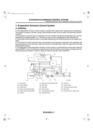
  • 1. EMISSION CONTROL (AUX. EMISSION CONTROL DEVICES) EVAPORATIVE EMISSION CONTROL SYSTEM EC(H4SO)-11 7. Evaporative Emission Control System A: GENERAL The evaporative emission control system prevents fuel vapors from escaping into atmosphere. This system includes a canister, purge control solenoid valve, fuel cut valve, and the lines connect- ing them. Fuel vapors in the fuel tank is introduced into the canister through the evaporation line, and are absorbed by activated carbon in it. The fuel cut valve is also incorporated in the fuel tank line. The purge control solenoid valve is controlled optimally by the ECM according to the engine con- dition. The pressure control solenoid valve incorporated in the fuel tank evaporation line regulates the pressure/vacuum in the fuel tank under the control of the ECM which uses the signal from the fuel tank pressure sensor. The diagnosis of the evaporative emission control system is performed by turning each solenoid valve ON/OFF to vary the pressure inside the fuel tank and measure this pressure change with the fuel tank pressure sensor in order to check for leaks and proper valve operation. (1) Fuel gauge (7) Pressure control solenoid valve (13) Fuel tank (2) Intake manifold (8) Drain valve (14) Fuel cut valve (3) Throttle body (9) Drain filter (15) Fuel tank pressure sensor (4) Purge control solenoid valve (10) Shut-off valve (16) Vent valve (5) Engine control module (ECM) (11) Fuel temperature sensor (17) Fuel tank sensor control valve (6) Canister (12) Fuel level sensor (1) (2) (3) (4) (5) (6)(7) (8)(9)(11) (10) (12)(13) (14) (16) (15) (17) EC-00021 W1860BE.book Page 11 Tuesday, January 28, 2003 11:01 PM
  • 2. EMISSION CONTROL (AUX. EMISSION CONTROL DEVICES) EVAPORATIVE EMISSION CONTROL SYSTEM EC(H4SO)-12 B: FUEL CUT VALVE The fuel cut valve is built onto the evaporation pipe of the fuel tank. The rising level of the fuel in the fuel tank causes the float to move up and close the cap hole so that no fuel can flow to the evapo- ration line. (1) Float (A) To canister (B) Valve open (C) Valve closed (1) (1) (A) (B) (C) EC-00022 W1860BE.book Page 12 Tuesday, January 28, 2003 11:01 PM
  • 3. EMISSION CONTROL (AUX. EMISSION CONTROL DEVICES) EVAPORATIVE EMISSION CONTROL SYSTEM EC(H4SO)-13 C: FUEL TANK CAP The fuel tank cap has a relief valve which prevents development of vacuum in the fuel tank in the event of a problem with the fuel vapor line. When there is no problem with the fuel vapor line, the filler pipe is sealed at the portion (A) and by the seal pressed against the filler pipe end. If vacuum develops in the fuel tank, the atmospheric pressure forces the spring down to open the valve; consequently outside air flows into the fuel tank, thus controlling the inside pressure. (1) Seal (2) Spring (3) Valve (4) Filter (4) (1) (2) (3) A EC-00023 W1860BE.book Page 13 Tuesday, January 28, 2003 11:01 PM
  • 4. EMISSION CONTROL (AUX. EMISSION CONTROL DEVICES) EVAPORATIVE EMISSION CONTROL SYSTEM EC(H4SO)-14 D: CANISTER The charcoal filled in the canister temporarily stores fuel vapors. When the purge control solenoid valve is opened by a signal from the ECM, the external fresh air entering the canister carries the fuel vapors into the intake manifold. (1) Grid (A) To purge control solenoid valve (2) Filter (B) From fuel tank (3) Activated charcoal (C) Air (4) Filter (5) Spring (1) (2) (3) (4) (A) (B) (5) (C) EC-00024 W1860BE.book Page 14 Tuesday, January 28, 2003 11:01 PM
  • 5. EMISSION CONTROL (AUX. EMISSION CONTROL DEVICES) EVAPORATIVE EMISSION CONTROL SYSTEM EC(H4SO)-15 E: PURGE CONTROL SOLENOID VALVE The purge control solenoid valve is on the evaporation line between the canister and intake mani- fold. The valve is installed under the intake manifold. (A) To canister (B) To intake manifold (A) (B) EC-00025 W1860BE.book Page 15 Tuesday, January 28, 2003 11:01 PM
  • 6. EMISSION CONTROL (AUX. EMISSION CONTROL DEVICES) EVAPORATIVE EMISSION CONTROL SYSTEM EC(H4SO)-16 F: PRESSURE CONTROL SOLENOID VALVE The fuel tank pressure control solenoid valve is located in the evaporation line between the canister and the fuel tank. When the tank inside pressure becomes higher than the atmospheric pressure, the valve is opened allowing fuel vapors to be introduced into the canister. On the other hand, when the tank inside pressure becomes lower than the atmospheric pressure, external air is taken from the drain valve into the canister. The pressure control solenoid valve can also be electrically closed for diagnosis of the evaporative emission control system. (1) Filter (A) Atmospheric pressure (2) Coil (B) Shut-off valve (3) Connector terminal (C) To fuel tank (4) Diaphragm (5) Valve (1) (2) (3) (4) (5) (A) (B) (C) EC-00026 W1860BE.book Page 16 Tuesday, January 28, 2003 11:01 PM
  • 7. EMISSION CONTROL (AUX. EMISSION CONTROL DEVICES) EVAPORATIVE EMISSION CONTROL SYSTEM EC(H4SO)-17 G: DRAIN FILTER The drain filter is installed at the air inlet port of the drain valve. It cleans the air taken in the canister through the drain valve. (1) Cap (A) To drain valve (2) Element (B) To atmosphere (3) Case (1) (2) (A) (B) (3) EC-00027 W1860BE.book Page 17 Tuesday, January 28, 2003 11:01 PM
  • 8. EMISSION CONTROL (AUX. EMISSION CONTROL DEVICES) EVAPORATIVE EMISSION CONTROL SYSTEM EC(H4SO)-18 H: VENT VALVE The vent valve is located in the fuel tank. During filling the fuel tank, fuel vapors are introduced into the canister through the vent valve. When the fuel vapor pressure becomes higher than the atmospheric pressure and overcomes the spring force which is applied to the back side of the diaphragm, the port toward the canister is opened. The vent valve also has a float which rises and block the port toward the canister when the fuel is full. (1) Spring (A) To filler pipe (2) Diaphragm (B) To canister (3) Plate cover (4) Packing (5) Float (6) Float spring (A) (1) (2) (B) (3) (4) (5) (6) EC-00028 W1860BE.book Page 18 Tuesday, January 28, 2003 11:01 PM
  • 9. EMISSION CONTROL (AUX. EMISSION CONTROL DEVICES) EVAPORATIVE EMISSION CONTROL SYSTEM EC(H4SO)-19 I: SHUT-OFF VALVE The shut-off valve is located at the top of the fuel filler pipe. When a filler gun is inserted into the filler pipe, the shut-off valve closes the evaporation line. (1) Pin (A) To canister (2) Valve (B) To fuel tank (3) Spring (4) Plate (5) Shaft (6) Pin (1) (2) (B)(A) (3) (4) (6) (5) EC-00029 W1860BE.book Page 19 Tuesday, January 28, 2003 11:01 PM
  • 10. EMISSION CONTROL (AUX. EMISSION CONTROL DEVICES) EVAPORATIVE EMISSION CONTROL SYSTEM EC(H4SO)-20 J: DRAIN VALVE The drain valve is located on the line connecting the drain filter and canister, just below the drain filter. The drain valve is forcibly closed by a signal from the ECM while the evaporation system di- agnosis is being conducted. (1) Magnetic plate (6) Valve (2) Yoke (7) Plate (3) Packing (8) Retainer (4) Spring (9) Moving core (5) Valve seat (10) Bobbin (1) (2) (3) (4) (5) (6) (7) (8)(9) (10) EC-00030 W1860BE.book Page 20 Tuesday, January 28, 2003 11:01 PM
  • 11. EMISSION CONTROL (AUX. EMISSION CONTROL DEVICES) EVAPORATIVE EMISSION CONTROL SYSTEM EC(H4SO)-21 K: FUEL TANK SENSOR CONTROL VALVE The fuel tank sensor control valve is installed on the top of the fuel tank and its one end is connected to the fuel tank pressure sensor while its other end is open to the atmosphere. Normally the passage to the fuel tank pressure sensor is open to the atmosphere, however, the pas- sage is closed when the ECM sends a signal to make a diagnosis of the evaporative emission con- trol system. (A) Fuel tank pressure sensor (B) Atmosphere (B) (A) EC-00214 W1860BE.book Page 21 Tuesday, January 28, 2003 11:01 PM
  • 12. EMISSION CONTROL (AUX. EMISSION CONTROL DEVICES) EVAPORATIVE EMISSION CONTROL SYSTEM EC(H4SO)-22 L: FUEL TANK PRESSURE SENSOR The fuel tank pressure sensor is installed on the top of the fuel tank and measures the pressure in the fuel tank. The measured pressure is converted into an electrical signal and sent to the ECM for diagnosis of the evaporative emission control system. (1) Connector (A) Output voltage (2) Terminal (B) Input pressure (C) To fuel tank (D) To fuel tank sensor control valve (A) (2) (1) (B) (D) (C) EC-00213 W1860BE.book Page 22 Tuesday, January 28, 2003 11:01 PM