Optimization of Separator Train in Oil Industry
•
0 gostou•34 visualizações

https://irjet.net/archives/V4/i7/IRJET-V4I7280.pdf

Recomendados
Recomendados
Mais conteúdo relacionado
Mais procurados
Mais procurados (20)
Semelhante a Optimization of Separator Train in Oil Industry
Semelhante a Optimization of Separator Train in Oil Industry (20)
Mais de IRJET Journal
Mais de IRJET Journal (20)
Último
Último (20)
Optimization of Separator Train in Oil Industry
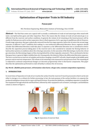
- 1. International Research Journal of Engineering and Technology (IRJET) e-ISSN: 2395-0056 Volume: 04 Issue: 07 | July -2017 www.irjet.net p-ISSN: 2395-0072 © 2017, IRJET | Impact Factor value: 5.181 | ISO 9001:2008 Certified Journal | Page 1269 Optimization of Separator Train in Oil Industry Pawan jaina M.E. Petroleum Engineering, Maharashtra Institute of Technology, Pune-411038 ---------------------------------------------------------------------***--------------------------------------------------------------------- Abstract - The fluid that comes out a typical well is actually a combination of crude oil and natural gas often mixed with water, non-hydrocarbon gases and other impurities. That is the reason why the volume of crude oil and natural gas is so different from the reservoir and surface conditions. In general, the volume of oil remaining at the lowest pressure will be smaller for flash process and in surface separators, there is flash expansion of oil i.e. gasstaysinequilibriumwithoil.However, If multi-stage separation, then gas is physically removed from the first stage separator, before the oil enters the second stage separator at different P and T conditions thus making it a non-isothermal differential liberation. Hence, engineers should consider that differential liberation could take place in separator as the differential liberation test is considered to better describe the separation process taking place in the reservoir and is also considered to simulate the flowing behavior of hydrocarbon systems at conditions above the critical gas saturation. As the saturation of the liberated gas reaches the critical gas saturation, the liberated gas begins to flow, leaving behind the oil that originally contained it. This is attributed to the fact that gases have, in general, higher mobility than oils. Consequently, this behavior follows the differential liberation sequence. The test is carried out on reservoir oil samples and involves charging a visual PVT cell with a liquid sample atthe bubble-point pressure and at reservoir temperature. The volume of oil remaining is also measured at each pressure level.Theremainingoil is subjected to continual compositional changes as it becomes progressively richer in the heavier components. This paper describes the optimization performed in crude oil facility to enhance the oil recovery. Key Words: (Bubble point pressure, oil formation value factor, oil-gas ratio, constant composition expansion.) In recent times of Separation of crude oil as it reaches the surface from the reservoir it must be processed so thatitcanbesent either to storage or to a refinery for further processing. In fact, the main purpose of the surface facilities is to separate the produced multiphase stream into its vapor and liquid fractions. On production platforms,a multiphaseseparatorisusuallythe first equipment through which the well fluid flows, followed by other equipment such as heaters, exchangers, and distillation column as shown in Figure 1. Fig:-1: Separation of reservoir fluid. 1. INTRODUCTION
- 2. International Research Journal of Engineering and Technology (IRJET) e-ISSN: 2395-0056 Volume: 04 Issue: 07 | July -2017 www.irjet.net p-ISSN: 2395-0072 © 2017, IRJET | Impact Factor value: 5.181 | ISO 9001:2008 Certified Journal | Page 1270 2. SEPARATION Separator tests are conducted to determine the changes in the volumetric behavior of the reservoir fluid as the fluid passes through the separator (or separators) and then into the stock. The resulting volumetric behaviorisinfluencedtoa largeextent by the operating conditions, i.e., pressures and temperatures, of the surface separation facilities. The primary objective of conducting separator tests, therefore, is to provide the essential laboratory information necessary for determining the optimum surface separation conditions, which in turn will maximize the stock-tank oil production. In addition, the results of the test, when appropriately combined with the differential liberation test data, provide a means of obtaining the PVT parameters (Bo, Rs, and Bg) required for petroleum engineering calculations. These separator testsareperformedonlyonthe original oil at the bubble point.The test involves placing a hydrocarbon sample at its saturation pressure and reservoir temperature in a PVT cell. The volume of the sample is measured as Vsat. The hydrocarbon sample is then displaced and flashed through a laboratory multistage separator system—commonly one to three stages. The pressure and temperature of these stages are set to represent the desired or actual surfaceseparationfacilities.Thegasliberatedfromeachstage isremoved and its specific gravity and volume at standard conditions are measured. The volume of the remaining oil in the last stage (representing the stock-tank condition) is measured and recorded as (Vo)st. These experimental, measured data can then be used to determine the oil formation volume factor and gas solubility at the bubble-point pressure as follows: The above laboratory procedure is repeated at a series of different separator pressures andata fixedtemperature. Itisusually recommended that four of these tests be used to determine the optimum separator pressure, which is usually considered the separator pressure that results in minimum oil formation volume factor. At the samepressure,thestock tank oil gravitywill be maximum and the total evolved gas, i.e., the separator gas and the stock-tank gas will be at a minimum. 2.1 One separator test: The goal of the one‐separator test is to find the separation pressure and temperature such that the solution gas oil ratio at the bubble point is a minimum, the API gravity of the oil at stock tank conditions is a maximum, andtheformationvolumefactorat the bubble point (BoSb ) is a minimum. 2.2 Two or more separator test: The objective here is the same as with one separator (obtain a maximum API gravity oil), but here you need to optimize the pressure and temperature of two separators. We use the output from one of these teststo illustrate the calculation procedure. 2.3 Flash and Differential liberation test: In order to measure GOR lab measurements of crude oil the two basic laboratory experiments are: 1. Flash liberation: In flash liberation, crude oil is flashed in separator, therefore less Rs & Bo from the solution— hence, gas remains in equilibrium with oil and Overall hydrocarbon composition remains same (components are re-distributed between the gas and liquid phase).
- 3. International Research Journal of Engineering and Technology (IRJET) e-ISSN: 2395-0056 Volume: 04 Issue: 07 | July -2017 www.irjet.net p-ISSN: 2395-0072 © 2017, IRJET | Impact Factor value: 5.181 | ISO 9001:2008 Certified Journal | Page 1271 2. Differential liberation: At each stage of depletion gas physically removes from contact with oil and there is continual change of fluid composition on the other hand Remaining hydrocarbons in progressively become heavier (mol. wt. continually increases). 3. METHODOLOGY & CALCULATIONS Constant compositional expansion and Differential liberation test: The following compositional information as shown in table 1 computed by PETE 310 for Reservoir fluids will help us in interpreting our results. The reservoir temperature is T= 220 F and the initial reservoir pressure is 2200 psia Constant Composition Expansion (CCE) Results. Table 2 shows the CCE data with pressure steps of 200 psia, here the experiment ends at 200 psia The tabledisplaystheliquid and vapor fraction, the compressibility factor, and the volumes of oil and gas at each pressure stage. From this table we can find the bubble point pressure graphically. Table 1— Compositional data of crude oil sample. Table 2 –Constant composition expansion results. Component Mol. Wt. Pc (psia) Tc (ᶞF) Accentric factor Moles Zi Methane 16 667.4 -116.9 0.008 48.5 0.36283384 Ethane 30 708.5 89.7 0.098 9.67 0.07234234 n-pentane 72.2 489.5 385.3 0.251 10 0.0748111 n-hexane 86 477.2 453.5 0.275 65.5 0.49001272 Pressure (PSI) Fw Fo Fg Zw Zo Zg vw(cc) vo (cc) vg (cc) 2200 0.0000 1.0000 0.0000 0.0000 0.5240 0.0000 0.0000 14.5072 0.0000 2000 0.0000 1.0000 0.0000 0.0000 0.4833 0.0000 0.0000 14.7182 0.0000 1800 0.0000 1.0000 0.0000 0.0000 0.4420 0.0000 0.0000 14.9569 0.0000 1600 0.0000 1.0000 0.0000 0.0000 0.4001 0.0000 0.0000 15.2307 0.0000 1400 0.0000 0.9972 0.0028 0.0000 0.3884 0.8042 0.0000 15.2694 0.0886 1200 0.0000 0.8366 0.1634 0.0000 0.3114 0.8352 0.0000 13.2223 6.9278 1000 0.0000 0.7622 0.2378 0.0000 0.2650 0.8532 0.0000 12.3008 12.3578 800 0.0000 0.6947 0.3053 0.0000 0.2168 0.8713 0.0000 11.4667 20.2564 600 0.0000 0.6286 0.3714 0.0000 0.1666 0.8897 0.0000 10.6317 33.5403 400 0.0000 0.5535 0.4465 0.0000 0.1140 0.9078 0.0000 9.6088 61.7229 200 0.0000 0.4134 0.5866 0.0000 0.0587 0.9229 0.0000 7.3857 164.8516
- 4. International Research Journal of Engineering and Technology (IRJET) e-ISSN: 2395-0056 Volume: 04 Issue: 07 | July -2017 www.irjet.net p-ISSN: 2395-0072 © 2017, IRJET | Impact Factor value: 5.181 | ISO 9001:2008 Certified Journal | Page 1272 From P-V graph by the intersection of two lines we can see that the bubble point pressure for this mixture is between 1600 & 1400 psia. Refining the search provides Pb = 1545 psi, note that at this pressure the volume of gas obtained is very small. Differential liberation Table 3 displays the differential liberation results for our example mixture. This output includes the fraction of liquid and vapour, the compressibility factor, and the volume of oil and gas at the specified pressure and temperature.Thisvolumeofgas is removed from the cell before the next expansion. Using data from this table we can compute Rsd , Bod, and Bg as indicated below in calculations. Table 3 – Differential liberation results at T =220ᶞF Separator Tests The objectives of the separator tests are to optimize the amount of oil produced at the surface. You will conduct tests with one and two separators; your goal is to find the best pressure and temperature combinations (for one or multiple separators)that maximize liquid production. The stock tank, which acts asanotherseparatoratstandardtemperatureandpressure, isincluded automatically in your computation. The goal of the one‐separator test is to find the separationpressureandtemperaturesuch that the solution gas oil ratio at the bubble point is a minimum, the API gravity of the oil at stock tank conditionsisa maximum, and the formation volume factor at the bubble point (Bosb ) is a minimum. Pressure (Psi) Fo Fg Zo Zg Vo , cm*3 Vg, cm*3 1545 1.0000 0.0000 0.3966 0.0000 11.9553 0.0000 1000 0.9429 0.0571 0.2653 0.8154 11.6517 2.1677 500 0.7892 0.2108 0.1469 0.8974 10.1858 16.6163 100 0.8114 0.1886 0.0325 0.9711 9.1343 63.4813 14.7 0.9234 0.0766 0.0049 0.9886 8.7055 144.8846 14.7 psi, 60F 1.0000 0.0000 0.0049 0.0000 8.7055 0.0000
- 5. International Research Journal of Engineering and Technology (IRJET) e-ISSN: 2395-0056 Volume: 04 Issue: 07 | July -2017 www.irjet.net p-ISSN: 2395-0072 © 2017, IRJET | Impact Factor value: 5.181 | ISO 9001:2008 Certified Journal | Page 1273 Table 4 – Single separator test results One Separator Test Results Table 4 shows the PVT properties from the example mixture at its bubble point (computedearlier)andata separatorpressure and temperature of 150 psia and 100 ᶞ F. The corresponding PVT properties from the separator test are computed as follows: 1. Bosb = volume of oil at bubblepoint pressure/volume of oil at standard conditions ( in bbl/sto). = 15.2694/8.4342 = 1.81 bbl/sto 2. The volume of gas released from the separator at standard conditions : Vsc1 = (Ps.Vs/Zs.Ts)×(Tsc.Psc) = = 1257.88 cm3. 3. The solution‐gas ‐oil ‐ratio of the separator is then : RsSb = Vsc+Volume of gas at standard conditions / Volume of oil at standard conditions (in scf/sto) = scf/sto =934.121 scf/sto 4. Density of oil at standard conditions : ρo (Tsc, psc) = 44.5354 lbm/ft3 or in API = 141.5/(44.5354/62.4)-131.5 = 66.77 Two Separators The objective here is the same as with one separator (obtain a maximum API gravity oil), but here we need to optimize the pressure and temperature of two separators. We use the output from oneoftheseteststoillustratethecalculationprocedure. In this example we chose Separator 1 at 500 psia and 100 ᶞF and Separator 2 at 100 psia and 80 ᶞF. The corresponding PVT properties from this separator test are computed as follows: Pressure (psia) T (ᶞF) Fo Fg Z0 Zg Vo in cm3 Vg( cm3 ) ρo ,( lb /ft3) ρg, (lb /ft3) 1545 220 0.9972 0.0028 0.3884 0.8042 15.2694 0.0886 30.3073 6.6528 150 100 0.5871 0.4129 0.0466 0.9640 9.1312 132.7221 42.5594 0.5587 14.7 60 0.9208 0.0792 0.0049 0.9898 8.4342 145.4989 44.5354 0.0893
- 6. International Research Journal of Engineering and Technology (IRJET) e-ISSN: 2395-0056 Volume: 04 Issue: 07 | July -2017 www.irjet.net p-ISSN: 2395-0072 © 2017, IRJET | Impact Factor value: 5.181 | ISO 9001:2008 Certified Journal | Page 1274 1. Bosb =volume of oil at bubble point pressure/volume of oil at standard conditions (in bbl/sto) = 15.2694/8.6498 = 1.76 bbl/sto. 2. The volume of gas released from the separator at standard conditions: (a.)Vsc1 = (Ps.Vs.Tsc /Zs.Ts.Psc)……………… (At 500 psia and 100 ᶞf). Table 5 – Two separator test results = = 914.99 cm3 (b.)Vsc2 = (Ps.Vs.Tsc /Zs.Ts.Psc)………………. (at 100 psia and 80 ᶞf) = = 335.27 cm3 3. The total solution‐gas –oil‐ratio is the sum of all volumes of gas released in each stage divided the oil volume at standard conditions : RsSb = Vsc1 + Vsc2 + volume of gas at standard conditions/volume of oil at standard conditions . = scf/sto. = 902.29 scf/sto. 4. Density of oil at standard conditions: ρo (Tsc, psc) = 44.4944 in lbm/ft3 or in API = 141.5/(44.4944/62.4)-131.5 = 66.94 Table 5 – Two separator test results In the above case, we have lower Bosb, and higher API gravity than in the previous n case. Clearly, byaddinga separationstage we will have a better oil quality and less gas production 4. CONCLUSION AND SCOPE In general the volume of oil remaining at the lowest pressure will be smaller for flash expansion & in separator there is flash expansion of oil. However if multi-stag separation is done then gas is physically removed from the first stageseparator,before the oil enters the second stage separator at different P & T conditions thus makingitisasnon-isothermal differential liberation .Hence engineers should consider that multi-stage separation could take placeinseparatorsasthedifferential liberationtestis P,psia T *f Fo Fg Zo Zg Vo , cm3 Vg , cm3 ρo, lb/ft3 ρg, lb/ft3 1545 220 0.9972 0.0028 0.3884 0.8042 15.2694 0.0886 30.3073 6.6528 500 100 0.7104 0.2896 0.1440 0.9098 10.2350 26.3569 40.7404 1.7375 100 80 0.8449 0.1551 0.0325 0.9715 9.0628 49.7227 43.9127 0.3822 14.7 60 0.9254 0.0746 0.0049 0.9887 8.6498 139.9513 44.4944 0.0936
- 7. International Research Journal of Engineering and Technology (IRJET) e-ISSN: 2395-0056 Volume: 04 Issue: 07 | July -2017 www.irjet.net p-ISSN: 2395-0072 © 2017, IRJET | Impact Factor value: 5.181 | ISO 9001:2008 Certified Journal | Page 1275 considered to better describe the separation process taking place in reservoir and is also considered to simulate the flowing behavior of hydrocarbon systems at conditions above the critical gas saturation, as the saturation of gas reaches critical gas saturation, the liberated gas begins to flow leaving behind the oil original contained in it .This is attributed from the fact that gas have higher mobility than oils. 5. REFERENCES 1. H.Y. Al-yousef (king fahd university of petroleum and minerals) | M.A. Al-marhoun (king fahd university of petroleum and minerals) published by journal of Canadian petroleum technology, march 1995. 2. Ali Pourahmadi Laleh and William Y. Svrcek, University of Calgary, “Computational Fluid Dynamics-Based Study of an Oilfield Separator” 3. McCain, W.D. Jr. : “ Analysis of Black oil PVT reports Revisited,” paper SPE 77386 presented at the SPE Annual Conference and Exhibition, San Antonio ,Texas ,29 sept – 2 oct. 4. Moses, P.L.: “Engineering Applications of Phase Behavior of Crude Oil and Condensate Systems,” JPT (July 1986) 715. 5. Al-Marhoun, M.A.: “Adjustment of Differential Liberation Data to Separator Conditions,” paper SPE 68234 presented at the 2001 SPE Middle East Oil Show, Bahrain, 17–20 March. 6. Instructional materials for reservoir fluids class from Prof. Maria A Barrufet, Texas A&M University.