Modeling and Analysis of Gas Turbine Rotor Blade
•
1 gostou•90 visualizações

https://irjet.net/archives/V4/i12/IRJET-V4I1227.pdf

Recomendados
Recomendados
Mais conteúdo relacionado
Mais procurados
Mais procurados (20)
Semelhante a Modeling and Analysis of Gas Turbine Rotor Blade
Semelhante a Modeling and Analysis of Gas Turbine Rotor Blade (20)
Mais de IRJET Journal
Mais de IRJET Journal (20)
Último
Último (20)
Modeling and Analysis of Gas Turbine Rotor Blade
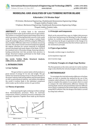
- 1. International Research Journal of Engineering and Technology (IRJET) e-ISSN: 2395-0056 Volume: 04 Issue: 12 | Dec-2017 www.irjet.net p-ISSN: 2395-0072 © 2017, IRJET | Impact Factor value: 6.171 | ISO 9001:2008 Certified Journal | Page 141 MODELING AND ANALYSIS OF GAS TURBINE ROTOR BLADE K.Ravindra1, P.V Divakar Raju2 1 PG Scholar, Mechanical Engineering, Chadalawada Ramanamma Engineering College, Tirupati, Andhra Pradesh, India. 2 Professor, Mechanical Engineering, Chadalawada Ramanamma Engineering College, Tirupati, Andhra Pradesh, India. ---------------------------------------------------------------------****--------------------------------------------------------------------- ABSTRACT - A turbine blade is the individual component which make up the turbine part of a gas turbine. The turbine is a mechanical power generating rotary device which uses power of flowing fluid and converts it into useful work. The aim of the project is to design a turbine blade using 3D modeling software CATIA by using the CMM point data available. CMM data taken from coordinate measuring machine. This project involve structural analysisbyapplying the angular velocities for various materials in evaluating stresses developed and mode shapes of the blade. CATIA is the standard tool in 3D product design, featuring industry- leading productivity tool that promote best practices in design. Structural analysis performed on the blade using commercial software ANSYS. Key words: Turbine Blade; Structural Analysis; CMM.CATIA v5, ANSYS 14.5 1. INTRODUCTION 1.1 Gas Turbine The gas turbine is a power plant, which produces a great amount of energy for its size and weight. The gas turbine has found increasing service in the past 40 years in the power industry bothamongutilitiesandmerchantplants as well as petrochemical industry, and utilities throughout the world. A turbine blade is the individual component which makes up the turbine section of a gas turbine 1.2 Theory of operation Gases passing through an ideal gas turbine undergo three thermodynamic processes. These are isentropic compression, isobaric (constant pressure) combustion and isentropic expansion. Together these make up the Brayton cycle. 1.3 Principle and Components Work can be extracted from a gas at a higher inlet pressure to the lower back pressure by allowing it to flow through a turbine. In a turbine as the gas passes through, it expands. The work done by the gas is equivalent to the change of its enthalpy. It is a well known fact that the turbines operate on the momentum principle. 1.4 Types of gas turbine Normally a turbine stage is classified as (i) An impulsion stage and (ii) A reaction stage 1.5 Velocity Triangles of a Single Stage Machine The flow geometry at the entry and exit of a turbo machine stage is described by the velocity triangles at these stations. 2. METHODOLOGY To investigatethe total deformation difference of turbine blade, we have to simulate the method by the use of few computer aided software. In this method we follow a list of steps to complete the analysis. In our project, there is a need to compare the total deformation difference between the existing blade material and prosed blade material. Different stress which is employedontheturbinebladeiscalculatedby using ANSYS software. But, the design of the blade is carried by using Catia software.
- 2. International Research Journal of Engineering and Technology (IRJET) e-ISSN: 2395-0056 Volume: 04 Issue: 12 | Dec-2017 www.irjet.net p-ISSN: 2395-0072 © 2017, IRJET | Impact Factor value: 6.171 | ISO 9001:2008 Certified Journal | Page 142 3.DESIGN Steps to be followed to develop Turbine Rotor Blade. 1. Start Mechanical design Part Design. 2. Look for a reference point from where all dimensions are controlling 3. Start sketching using sketch tools 4. Taking Y-Z plane as reference plane for sketching. 5. By using the CMM point data we are creating construction points of a turbine blade which is in AEROFOIL shape. 6. By using SP line the construction are joined in order to achive AEROFOIL shape of Rotor Blade. 7. Then this 2-D sketch is converted into a 3-D element by using PAD DEFINITION after exiting the work bench. 8. Then to create the base of the turbine blade work bench is selected and drawn to the required dimensions as mentioned in the specifications. 9. This base which is in shape of I-section isExtruded by using PAD DEFINTION 10. The model of the blade is finished and this file is saved in two formats, one as .CATpart extension file and another as .igs extension . 11. Where, .CATpart is used for drafting. Andthisdrafted file is saved as .CATDrawing as extension file. 4 MATERIAL DATA Here to find out the best suited material for gas turbine blade three different materials are considered as: 1. Titanium alloy Ti6Al4V 2. Structural steel 3. Titanium alloy Ti-8Al-1Mo-1V
- 3. International Research Journal of Engineering and Technology (IRJET) e-ISSN: 2395-0056 Volume: 04 Issue: 12 | Dec-2017 www.irjet.net p-ISSN: 2395-0072 © 2017, IRJET | Impact Factor value: 6.171 | ISO 9001:2008 Certified Journal | Page 143 4.1 TITANIUM ALLOY (Ti6Al4V) Titanium Alloy (Ti6Al4V) > Constants Density 4.429e-006 kg mm^-3 Specific Heat 5.26e+005 mJ kg^-1 C^-1 Titanium Alloy (Ti6Al4V) > Isotropic Elasticity Temperature C Young's Modulus MPa Poisson's Ratio Bulk Modulus GPa Shear Modulus GPa 110000 0.33 125 43 Titanium Alloy (Ti6Al4V) > Bilinear Isotropic Hardening Yield Strength MPa Tangent Modulus MPa Temperature C 1480 2160 1878 4.2 STRUCTURAL STEEL Structural Steel > Constants Density 7.85e-006 kg mm^-3 Coefficient of Thermal Expansion 1.2e-005 C^-1 Specific Heat 4.34e+005 mJ kg^-1 C^-1 Thermal Conductivity 6.05e-002 W mm^-1C^-1 Resistivity 1.7e-004 ohm mm Structural Steel > Compressive Yield Strength Compressive Yield Strength MPa 250 Structural Steel > Tensile Yield Strength Tensile Yield Strength MPa 250 4.3 TITANIUM ALLOY Ti-8Al-1Mo-1V Titanium Alloy > Constants Density 4.62e-006 kg mm^-3 Coefficient of Thermal Expansion 9.4e-006 C^-1 Specific Heat 5.22e+005 mJ kg^-1 C^-1 Thermal Conductivity 2.19e-002 W mm^-1C^-1 Resistivity 1.7e-003 ohm mm Titanium Alloy > Compressive Yield Strength Compressive Yield Strength MPa 930 Titanium Alloy > Tensile Yield Strength Tensile Yield Strength MPa 930 Titanium Alloy > Tensile Ultimate Strength Tensile Ultimate Strength MPa 1070 Titanium Alloy > Isotropic Secant Coefficient ofThermal Expansion Reference Temperature C 22 5.ANALYSIS STRUCTURAL ANALYSIS: The structural analysis is the most common analysis of finite element method, which accomplishes various structures such as bridges, naval, aeronautical, mechanism housing and mechanism components such as possible in ANSYS software. Here in our project Static analysis is done on different materials to find out 5.1 Imported Solid Model of Gas Turbine blade
- 4. International Research Journal of Engineering and Technology (IRJET) e-ISSN: 2395-0056 Volume: 04 Issue: 12 | Dec-2017 www.irjet.net p-ISSN: 2395-0072 © 2017, IRJET | Impact Factor value: 6.171 | ISO 9001:2008 Certified Journal | Page 144 5.2 MESHED SOLID MODEL 5.3 BOUNDARY CONDITIONS This is the place where different conditionsare employed on the gas turbine blades which are: 1. Fixed Support, 2. Load and 3. Thermal condition 5.3.1 FIXED SUPPORT 5.3.2 LOAD ON GAS TURBINE ROTOR BLADE 5.3.3THERMALCONDITION 5.4 Total Deformation acting on different types of materials 5.4.1 TITANIUM ALLOY Ti6Al4V 5.4.2 STRUCTURAL STEEL
- 5. International Research Journal of Engineering and Technology (IRJET) e-ISSN: 2395-0056 Volume: 04 Issue: 12 | Dec-2017 www.irjet.net p-ISSN: 2395-0072 © 2017, IRJET | Impact Factor value: 6.171 | ISO 9001:2008 Certified Journal | Page 145 5.4.3 TITANIUM ALLOY Ti-8Al-1Mo-1V 5.5 MAX VON MISSES STRESSES INDUCED ON DIFFERENT MATERIALS 5.5.1 TITANIUM ALLOY Ti6Al4V 5.5.2 STRUCTURAL STEEL 5.5.3 TITANIUM ALLOY Ti-8Al-1Mo-1V 5.6 THERMAL STRAIN INDUCED ON DIFFERENT MATERIALS Thermal strain can be defined as the deformation of a material caused due to the temperature change occurred on it. 5.6.1 TITANIUM ALLOY Ti6Al4V 5.6.2 STRUCTURAL STEEL
- 6. International Research Journal of Engineering and Technology (IRJET) e-ISSN: 2395-0056 Volume: 04 Issue: 12 | Dec-2017 www.irjet.net p-ISSN: 2395-0072 © 2017, IRJET | Impact Factor value: 6.171 | ISO 9001:2008 Certified Journal | Page 146 5.6.3TITANIUM ALLOY Ti-8Al-1Mo-1V 6. RESULTS AND DISCUSSION RESULT TEBLES 7. CONCLUSION In this project we have designed a rotor bladewhich is usedasgasturbinerotorblade.Thisanalysis has been done on Titanium alloy Ti6Al4V, structural steel, Titanium alloy Ti-8Al-1Mo-1V by varying boundary conditions on them. This was successfully performed by using ANSYS 14.5 analysis software. By observing the analysis results, the analyzed stress values are less than their respective yield stress values. So our design is safe enough to be used in the real-time application. Here, titaniumalloyand structuralsteelareused in the manufacturing of the blades; Titanium alloy Ti-8Al- 1Mo-1V gives better results where structural steel is not satisfactory. But, Titanium alloy Ti6Al4V shows even better results than the regular Titanium alloy Ti-8Al-1Mo-1V. By theAnalysisresults,TotaldeformationofTi6Al4V gives 0.66748 when compared to Structural steel2.3294and Ti-8Al-1Mo-1V 1.8326. Thermal Strain of Ti6Al4V gives 0 mm//mm when compared to structural steel 0.009936 and Ti-8Al-1Mo-1V 0.0077832. Von MisesStressofTi6Al4Vgives 107.37 MPa when compared to Structural Steel 8361.4 MPa and Ti-8Al-1Mo-1V 2941.7 MPa So, by this we can conclude that, Titanium alloy Ti6Al4V shows better results under these simulated conditions than the othertwomaterials.Andhence,thisisthe best material to be used for the manufacturing of the blade and also it is safe. REFERENCES 1. K HariBrahmaiah, M. Lava Kumar, “Heat transfer analysis of gas turbine blade throughcoolingholes”. International journal of computational engineering research (IJCER) Vol 04, Issue 7, july- 2014. 2. Yoshio Samaizu Perez Zuniga, June 2011, Design Of Axial Turbine And Thermodynamic Analysis And Testing Of K03 Turbocharger. 3. Chaitanya Krishna Patsa, Subhani Mohammed, “Structural Analysis Of Super Alloy Gas Turbine Blade Using Fea”, Ijert, Vol3 Issue 1,January 2014. 4. Cyrus B.Meher-Homji, George Gabriles, “Gas Turbine Failures- Cause, Avoidance And Troubleshooting” 5. Jianfuhou, Bryon J. Wicks, Ross A. Antoniou, An Investigation Of Fatigue Failures Of Turbine Blades In A Gas Turbine Engine By Mechanical Analysis, Engineering Failure Analysis 9 (2002) 201-211.