IRJET - Dynamic Analysis of Steel Truss Bridge under Various Combinational Moving Loads
•
0 gostou•29 visualizações

https://irjet.net/archives/V7/i2/IRJET-V7I2343.pdf

Recomendados
Recomendados
Mais conteúdo relacionado
Mais procurados
Mais procurados (20)
Semelhante a IRJET - Dynamic Analysis of Steel Truss Bridge under Various Combinational Moving Loads
Semelhante a IRJET - Dynamic Analysis of Steel Truss Bridge under Various Combinational Moving Loads (20)
Mais de IRJET Journal
Mais de IRJET Journal (20)
Último
Último (20)
IRJET - Dynamic Analysis of Steel Truss Bridge under Various Combinational Moving Loads
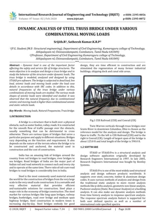
- 1. International Research Journal of Engineering and Technology (IRJET) e-ISSN: 2395-0056 Volume: 07 Issue: 02 | Feb 2020 www.irjet.net p-ISSN: 2395-0072 © 2020, IRJET | Impact Factor value: 7.34 | ISO 9001:2008 Certified Journal | Page 1638 DYNAMIC ANALYSIS OF STEEL TRUSS BRIDGE UNDER VARIOUS COMBINATIONAL MOVING LOADS Srijith.R1, Satheesh Kumar.K.R.P2 1(P.G. Student (M.E- Structural engineering), Department of Civil Engineering, Kumaraguru college of Technology, Athipalayam rd, Chinnavedampatti, Coimbatore, Tamil Nadu 641049) 2(Professor, Department of Civil Engineering Kumaraguru college of Technology, Athipalayam rd, Chinnavedampatti, Coimbatore, Tamil Nadu 641049) ---------------------------------------------------------------------***---------------------------------------------------------------------- Abstract - Dynamic load is one of the important factor affecting the safety and service life of bridge structures. The main objective is to analyze and design a truss bridge and to study the behavior of the structure under dynamic loads. The truss bridge is modeled, analyzed and designed by using STAAD pro software. The bridge is subjected to dead load, live load, seismic loads and moving loads under the load case details in accordance with IRC codes. In addition to this, natural frequencies of the truss bridge under various combinations of moving loads are studied. The various mode shapes of seismic loads were identified and studied. It was observed that the natural frequency due to combinational seismic and moving loadsishigherthancombinationalseismic and static vehicle loads. Key Words: Moving loads, Natural Frequencies, Trussbridge. 1.INTRODUCTION A bridge is a structure that is built over a physical obstacle, such as water bodies, valley,roads.Itisconstructed for the smooth flow of traffic passage over the obstacle, usually something that can be detrimental to cross otherwise. There are various types of bridges that serve a particular purpose and apply to different situations.Bridges vary depending on the function and requirement. It also depends on the nature of the terrain where the bridge is to be constructed and anchored, the material used in construction and the cost of construction. India has an amazing link of bridges around the country from rail bridges to road bridges, river bridges to sea bridges. Road bridges of India are the major part of Indian rail and road network to connect each and every city and to operate at the same time. There ratioofrail-cum-road bridges to road bridges is considerably less in India. Steel is the most commonly used material around the world for the construction of bridges from the verylarge scale to the very small scale construction. It is a versatileand very effective material that provides efficient and sustainable solutions for construction. Steel plays a major role in the economy of bridge construction .The steel market for various bridges like long span bridges, railway bridges, footbridges, road over bridge and medium span highway bridges. Steel construction in modern times is increasing day-by-day. Steel bridges embody for good design, they are time efficient in construction and are stimulated the regeneration of many former industrial buildings, shipping dock and canal side areas. Fig.1 CSX Railroad (CSX) and Conrail (CR) Twin Warren verticals through truss bridges over Scioto River in downtown Columbus, Ohio is chosen as the reference model for the analysis and design. The bridge is Open to traffic .To the left is CSX Railroad (CSX) and to the right is Conrail (CR). Length of largest span of the bridge is about 125.0 ft and total length of the bridge is 590.0 ft. 1.2 SOFTWARE STAAD or STAAD.Pro is a structural analysis and design software application originally developed by Research Engineers International in 1997. In late 2005, Research Engineers International was bought by Bentley Systems. STAAD.Pro is one of the most widelyusedstructural analysis and design software products worldwide. It supports over steel, concrete, timber & aluminum design codes. It uses various methods of analysis and design from the traditional static analysis to more recent analysis methods like p-delta analysis, geometricnon-linearanalysis, Pushover analysis (Static-Non Linear Analysis)ora buckling analysis. It can also make use dynamic analysis methods from time history analysis to response spectrum analysis. The response spectrum analysis feature is supported for both user defined spectra as well as a number of international code specified spectra.
- 2. International Research Journal of Engineering and Technology (IRJET) e-ISSN: 2395-0056 Volume: 07 Issue: 02 | Feb 2020 www.irjet.net p-ISSN: 2395-0072 © 2020, IRJET | Impact Factor value: 7.34 | ISO 9001:2008 Certified Journal | Page 1639 Our project involves analysis and design of Truss using a very popular designing software STAAD Pro. We have chosen STAAD Pro because of its followingadvantages: 1) easy to use interface, 2) conformation with the Indian Standard Codes, 3) versatile nature of solving any type of problem, 4) Accuracy of the solution. STAAD Pro features a state-of-the-artuserinterface, visualization tools, powerful analysis and design engines with advanced finite element and dynamic analysis capabilities. From model generation, analysis and design to visualization and result verification, STAAD Pro is the professional’s choice for steel, concrete, timber, aluminum and cold-formed steel design of low and high-rise buildings, culverts, petrochemical plants, tunnels, bridges, piles and much more. Main Steps Of Modeling Truss in STAAD PRO 1.3 OBJECTIVE To design and analyze a truss bridge. To study the behavior of truss bridge under moving loads and dynamic forces. To study the behavior of truss under various combinational loads. 2. MODELING AND ANALYSIS 2.1 BRIDGE MODELING The bridge is modeled in reference to the CSX and CONRAIL bridge. The type of truss modeled is warren vertical truss .The length of the bridge is assumed to be 30m .The height of the bridge is about 5m and width of bridge is 10m.Deck slab is provided with a thickness of 200mm. Fig 2: Bridge model All the members are assignedassteel members.The horizontal and inclined members are assigned as truss members. The vertical members are left free for rotation. Fig 3: Truss member The pinned supports are assigned at ends of the bridge model. The model is assigned with section properties and thickness of slab. The section propertiesareIsections as per Indian codes in STAAD Pro. Table 1: SECTION PROPERTIES Section Ref ID Material Thickness 200mm R1 Concrete I80016B50012 R3 Steel I80016B50016 R4 Steel I80016B50020 R2 Steel I80016B50040 R5 Steel
- 3. International Research Journal of Engineering and Technology (IRJET) e-ISSN: 2395-0056 Volume: 07 Issue: 02 | Feb 2020 www.irjet.net p-ISSN: 2395-0072 © 2020, IRJET | Impact Factor value: 7.34 | ISO 9001:2008 Certified Journal | Page 1640 Fig 4: Section Properties 2.2 LOAD CASE Dead load of 1 KN is assigned to the total structure and live load of 5 KN as floor load is provided as per IS 875 part 2 imposed loads (code of practice for design loads). 2.3 ANALYSIS The model is analyzed. The node displacement and support reaction results are identified and noted. 3. LOADS AND COMBINATIONS 3.1 TIME HISTORY METHOD The Le Centro earthquake data is been used as the seismic load for truss bridge. As, this earthquake has a higher magnitude of 7 and a maximumperceivedintensityof X (Extreme). The data’s collected are with respect to time and acceleration. The damping ratio of 0.05 with a time interval of 2 sec. 3.2 SEISMIC LOAD The seismic load is assigned with self weight and floor load of 1KN and 5KN in x, y, z direction. Loading type is defined as ground motion. Direction of seismic load is given as Z direction. Fig 5: Le Centro earthquake graph 3.3 IRC CLASSIFICATION OF ROAD BRIDGES IRC CLASS AA LOADING: This loading is to be adopted within certain municipal limits ,in certain existing or contemplated industrial areas ,in other specified areas ,and a long certain specified highways. Bridges designed for Class AA Loading should be checked for Class A Loading also, as under certain conditions, heavier stresses may occur under Class A Loading. IRC CLASS A LOADING: This loading is to be normally adopted on all roads on which permanent bridges and culverts are constructed. CLASS AA LOADING AS PER IRC 6 Fig 6 IRC class AA loading The deck slab isselectedand theroadwayisdefined. The lanes are customized with curb on both sides. The ‘n’ number of lanes can be created with the ‘define roadway’ dialog box. Fig 7: Define Roadway
- 4. International Research Journal of Engineering and Technology (IRJET) e-ISSN: 2395-0056 Volume: 07 Issue: 02 | Feb 2020 www.irjet.net p-ISSN: 2395-0072 © 2020, IRJET | Impact Factor value: 7.34 | ISO 9001:2008 Certified Journal | Page 1641 Fig 8: Lane Alignment The nodal displacements and support reactions which are noted are entered in ‘load generator parameters’ dialog box. Load case of class AA+A is applied to all three lanes individually. The loads are generated and loaded into model. Fig 9: Load Generator Fig 10: Load Generated result 3.4 LOAD COMBINATIONS The load combinations provide combined resultsof load case specified. The various load combinations used are as follows: 1.5(Dead load + Live load) DL+LL+SL+ML1, DL+LL+SL+ML2, DL+LL+SL+ML3, DL+LL+SL+ML1+ML2, DL+LL+SL+ML1+ML3, DL+LL+SL+ML3+ML2, DL+LL+SL+ML1+ML2+ML3. Where, DL - Dead load LL – Live load SL – Seismic load ML1 – Moving load class AA+A in lane 1 ML2 – Moving load class AA+A in lane 2 ML3 – Moving load class AA+A in lane 3 4. ANALYSIS RESULTS 4.1 MODE SHAPES Mode shapesarefoundandrecorded withrespectto seismic loads. Fig 9: Mode shape 1 Fig 10:Mode shape 2
- 5. International Research Journal of Engineering and Technology (IRJET) e-ISSN: 2395-0056 Volume: 07 Issue: 02 | Feb 2020 www.irjet.net p-ISSN: 2395-0072 © 2020, IRJET | Impact Factor value: 7.34 | ISO 9001:2008 Certified Journal | Page 1642 Fig 11:Mode shape 3 Fig 12:Mode shape 4 Fig 13:Mode shape 5 Fig 14:Mode shape 6 4.2 RESULTS WITH SEISMIC AND MOVING LOADS FREQUENCY RECORDED Table 2: Calculated Frequencies For Seismic Load Case MODE FREQUENCY (CYCLES/SEC) PERIOD(SEC) ACCURACY 1 5.065 0.19745 3.026E-09 2 5.519 0.18121 1.464E-09 3 5.601 0.17853 2.263E-08 4 5.785 0.17287 2.683E-09 5 6.423 0.15568 3.481E-08 6 7.245 0.13802 1.545E-07 MASS PARTICIPATION FACTOR The amount of system mass participating in that particular mode. A mode with a large effective mass is usually a significant contributor to the system's response. Table 3: Mass Participation Factors In Percent MODE X Y Z SUMM- X SUMM- Y SUMM- Z 1 0.00 0.00 11.61 0.000 0.000 11.612 2 0.00 0.00 0.00 0.000 0.000 11.612 3 0.00 0.00 0.43 0.000 0.000 12.046 4 0.00 0.00 0.00 0.000 0.000 12.046 5 0.00 91.69 0.00 0.000 91.693 12.046 6 0.00 0.00 3.64 0.000 91.693 15.686 4.3 RESULTS WITH SEISMIC AND STATIC VEHICLE LOAD Table 4: Frequency MASS PARTICIPATION FACTORS Table 5: Mass Participation Factors In Percent MODE X Y Z SUMM- X SUMM- Y SUMM- Z 1 0.00 0.00 8.54 0.000 0.000 8.537 2 0.00 0.00 0.00 0.000 0.000 8.537 3 0.00 0.00 0.64 0.000 0.000 9.175 4 0.00 0.00 0.00 0.000 0.000 9.175 MODE FREQUENCY (CYCLES/SEC) PERIOD (SEC) ACCURACY 1 4.934 0.20268 9.661E-09 2 5.518 0.18124 8.742E-10 3 5.595 0.17872 1.175E-08 4 5.785 0.17287 5.124E-09 5 5.893 0.16968 2.289E-08 6 6.829 0.14643 1.747E-07
- 6. International Research Journal of Engineering and Technology (IRJET) e-ISSN: 2395-0056 Volume: 07 Issue: 02 | Feb 2020 www.irjet.net p-ISSN: 2395-0072 © 2020, IRJET | Impact Factor value: 7.34 | ISO 9001:2008 Certified Journal | Page 1643 5 0.00 91.83 0.00 0.000 91.834 9.175 6 0.00 0.00 4.56 0.000 91.834 13.734 4.4 STEEL TAKE-OFF Total amount of steel quantity required is provided in table 6, Table 6: Steel quantity PROFILE LENGTH (m) WEIGHT(KN) ST I80016B50040 118.11 664.36 ST I80016B50020 92.24 359.26 ST I80016B50016 39.37 141.4 ST I80016B50012 74.8 244.6 TOTAL 1409.62 Fig 17: Frequency comparison Blue- seismic and static vehicle load Red- seismic and moving loads CONCLUSIONS 1. The truss bridge has been modeled and analyzed with moving loads of IRC class AA+A loading. 2. The response of the truss bridge under various combinational moving and seismic loads are studied. 3. Mode shapes were identified to be similar in both cases. 4. It was observed that the natural frequency due to combinational seismic and moving loads is higher than combinational seismic and static vehicle loads. 5. By conducting modal analysis it was found that the predominant mode shape was observedatfifth modeinboth combinational cases. REFERENCES 1. "3D Structural Analysis and Design Software - STAAD.Pro". Bentley.com. Retrieved 2016-07-27. 2. Development of finite element models to predict dynamic bridge response( final report). 3. Design and analysis of truss( Industry report ). 4. IRC:24-2010, ‘Standard specifications and code of practice for road bridges’, Section V, Steel Road Bridges (Limit State Method). 5. IRC: 6-2010, Standard Specifications and Code of Practice for Road Bridges, Section II, Loads and Stresses (Fifth Revision), India, 2010. 6. IS: 800-2007, Indian Standard, Code of Practice for General Construction in Steel (Based on Limit State Method), India, 2007. 7. IRC: SP: 37-1991, Guidelines for Evaluation of Load Carrying Capacity of Bridges, India, 1991. 8. Strengthening of Garudchatti bridge after failure of Chauras bridge (journal). The model in this journal has been studied and modeled through STAAD Pro.and analyzed. The results found were almost similar to the results in the journal. Fig 18: Reference model Fig 19: analysis of reference model