

Recomendados
Mais conteúdo relacionado
Mais procurados
Mais procurados (20)
Destaque
Destaque (10)
Semelhante a Structure & Infrastructure Planning
Semelhante a Structure & Infrastructure Planning (20)
Mais de Ir. Abdul Aziz Abas
Mais de Ir. Abdul Aziz Abas (9)
Structure & Infrastructure Planning
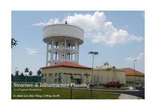
- 1. Structure & Infrastructure Planning Civil Engineer Perspective Ir. Abdul Aziz Abas P.Eng, C.PEng, Int.PE
- 2. PREFACE STRUCTURE & INFRASTRUCTURE PLANNING Preparation for life… • As a module of the Integrated Design Project course for the Bachelor of Civil Engineering programme, Faculty of Civil Engineering, UiTM, Shah Alam This program will provide basic overview of all aspects of Structure & Infrastructure Planning from Civil Engineer’s prospective Mar 2010 2
- 3. STRUCTURE & INFRASTRUCTURE PLANNING Contents Introduction Overview of Civil engineering and facts Project initiation, Professional Responsibility & Hierarchy Challenge Faced By Engineers Structure Plan Brief discussion on Importance of Structure Plan Role of Engineer Infrastructure Plan Engineer’s Responsibility, Approach & Methodology for infra & services Planning for ultimate and phase development Future Challenge Dealing with new requirements & compliances Q&A Mar 2010 3
- 4. Introduction
- 5. INTRODUCTION STRUCTURE & INFRASTRUCTURE PLANNING Overview Civil engineering is a professional engineering discipline that deals with the design, construction and maintenance of the physical and naturally built environment. FACTS • Engineer deals with facts and figures • Engineer’s responsibility & liability is for life (has no expiry date except death) • Engineer faces huge challenges to defend his works as “anybody” has capability to query • Engineer deals with safety of properties and lives • Engineer converts ideas to reality Mar 2010 5
- 6. INTRODUCTION STRUCTURE & INFRASTRUCTURE PLANNING CIVIL ENGINEERS A. SPECIALIST ENGINEERS B. GENERAL ENGINEERS • Geotechnical Engineer • Planning Engineer • Earthworks Engineer • Site Engineer • Roads Engineer • Maintenance Engineer • Drainage Engineer • Administrative Engineer • Water Supply Engineer • Sewerage Engineer Knowledgeable in many subjects but not • Marine / Port Engineer an expert Of any subject • Structural Engineer • Specialist Knowledgeable in less subjects but an expert Of that subject(s) Mar 2010 6
- 7. INTRODUCTION STRUCTURE & INFRASTRUCTURE PLANNING CIVIL ENGINEERS A. SPECIALIST ENGINEERS B. GENERAL ENGINEERS • Geotechnical Engineer • Planning Engineer • Earthworks Engineer • Site Engineer • Roads Engineer • Maintenance Engineer • Drainage Engineer • Administrative Engineer • Water Supply Engineer • Sewerage Engineer Knowledgeable in many subjects but not • Marine / Port Engineer an expert Of any subject • Structural Engineer • Specialist Knowledgeable in less subjects but an expert But, the Project Manager / Decision Maker Of that subject(s) come under this category Mar 2010 7
- 8. INTRODUCTION STRUCTURE & INFRASTRUCTURE PLANNING Project Initiation Early stage of a project, Engineer to… • Appreciate project • Confirm project’s expectation and milestones • Conform responsibilities & scope of works • Establish & confirm line of communication • Establish Organisation Chart & Programme of works Mar 2010 8
- 9. INTRODUCTION STRUCTURE & INFRASTRUCTURE PLANNING Typical Organisation Chart Mar 2010 9
- 10. INTRODUCTION STRUCTURE & INFRASTRUCTURE PLANNING Professional Responsibility & Hierarchy CLIENT / DEVELOPER PMC ARCHITECT / TOWN PLANNER (PSP) ENGINEERS SURVEYORS Q.S. LANDSCAPE SPECIALISTS (SP) MasterplanStage Design & Implementation Stage BUILDING WORKS CIVIL & INFRASTRUCTURE WORKS ARCHITECT (PSP) CIVIL ENGINEER (PSP) ENGINEERS SURVEYORS Q.S. LANDSCAPE ARCHITECTS SURVEYORS Q.S. LANDSCAPE SPECIALISTS (SP) SPECIALISTS (SP) (PSP) Principal Submitting Person (SP) Submitting Person Mar 2010 1 0
- 11. INTRODUCTION STRUCTURE & INFRASTRUCTURE PLANNING Basic PMC’s / PSP’s Responsibility • To establish Project’s Terms of Reference • To establish & obtain approval of Development layout plan • To obtain Development Order from Local Authority • To establish Scope of works for Consultants / Contractors • To establish and monitor implementation schedule • To coordinate all stages of works • To administer Tender exercise and award of Tender • To secure Certificate of Completion & Compliance (CCC) • To hand-over completed project to Client Mar 2010 11
- 12. INTRODUCTION STRUCTURE & INFRASTRUCTURE PLANNING Prior Requirement For Engineering Input Letter Of Appointment (LOA) Development Order Development Masterplan Layout Topographical Survey Plan Landuse Table Terms Of Reference / Scope of Works Development Schedule / Phasing Mar 2010 12
- 13. INTRODUCTION STRUCTURE & INFRASTRUCTURE PLANNING Challenges faced by Engineers Frequent Changes of Development Masterplan Layout Frequent Changes of Landuse Frequent Changes of Development Schedule / Phasing • To suit budget constraints • To suit business strategies • To suit Authority’s requirement • To suit crazy ideas Engineers to attend to promptly, professionally & courteously Mar 2010 13
- 14. Structure Plan
- 15. A PLANNING STRUCTURE & INFRASTRUCTURE PLANNING Structure Plan Structure Plan (SP) is a written statement that explains strategic policies and actions concerning the land use development in urban and rural areas, including steps to:- Improve physical environment Improve communications and traffic management Improve socio-economic levels, encourage economic growth Enhance rural planning Facilitate sustainable development Source : Department of Town and Country Planning, Peninsular Malaysia Mar 2010 15
- 16. A PLANNING STRUCTURE & INFRASTRUCTURE PLANNING Structure Plan SP also contains graphs, pictures and sketches to explain policies or suggestions brought forth Engineers to provide Infrastructure & Utilities sector Source : Department of Town and Country Planning, Peninsular Malaysia Mar 2010 16
- 17. A PLANNING STRUCTURE & INFRASTRUCTURE PLANNING Structure Plan Structure Plan Functions To interpret national and regional policies To establish general objectives, policies and suggestions To provide a framework for the preparation of local plans To provide development control guidelines To draw up decision-making guidelines To draft a basic development guide To expound on issues and decisions Source : Department of Town and Country Planning, Peninsular Malaysia Mar 2010 17
- 18. A PLANNING STRUCTURE & INFRASTRUCTURE PLANNING Structure Plan Source : Department of Town and Country Planning, Peninsular Malaysia Mar 2010 18
- 20. B PLANNING APPROACH STRUCTURE & INFRASTRUCTURE PLANNING Req’d for Water Supply, Sewerage, Solid Waste, Telco & Power planning DEVELOPMENT MASTERPLAN BY ARCHITECT / PLANNER Mar 2010 20
- 21. All Stages B PLANNING APPROACH STRUCTURE & INFRASTRUCTURE PLANNING Engineer’s Responsibility • Engineer to advise on all aspects of engineering Design Stage • Engineer to perform all preliminary and detail design works • Engineer to establish BQs and Engineer’s estimates • Engineer to establish Specification for engineering works • Engineer to obtain approvals for engineering works Tender Stage • Engineer to involve in Tender exercise Construction Stage • Engineer to supervise construction Post Construction Stage • Engineer to recommend / issue Certificate of Completion & Compliance (CCC) Mar 2010 21
- 22. B PLANNING APPROACH STRUCTURE & INFRASTRUCTURE PLANNING Engineer’s Tasks Upon obtaining the project, Engineers to carry out…. Desktop Study Preliminary Design Detail Design Construction Supervision Mar 2010 22
- 23. B PLANNING APPROACH STRUCTURE & INFRASTRUCTURE PLANNING Engineer’s Tasks A. DESKTOP STUDY • To Understand scope of works • Mandatory site visit • To confirm site location and development boundaries • To familiarize with the site geographical condition • To identify adjacent development, Access, etc. • To observe & assess site constraints • To have general idea of existing & future design system • To gather information about historical information Mar 2010 23
- 24. B PLANNING APPROACH STRUCTURE & INFRASTRUCTURE PLANNING B. PRELIMINARY DESIGN • To establish conceptual design • To obtain Client’s agreements • To obtain planning approval from respective Authority Mar 2010 24
- 25. B PLANNING APPROACH STRUCTURE & INFRASTRUCTURE PLANNING C. DETAIL DESIGN • To establish detail design • To obtain Client’s agreements • To obtain design approval from respective Authority Mar 2010 25
- 26. B PLANNING APPROACH STRUCTURE & INFRASTRUCTURE PLANNING D. CONSTRUCTION STAGE • To participate in Tender Evaluation • To supervise construction • To control construction progress • To recommend progress payments • To comply statutory requirements • To recommend / issue all Certificates Mar 2010 26
- 28. INFRASTRUCTURE STRUCTURE & INFRASTRUCTURE PLANNING A. Engineering Work Earthworks B. Infrastructure Roads Water Supply Drainage Sewerage Solid Waste Power Supply Telecommunication Not Civil but M&E Structures are part of Civil Engineering and existed in Infrastructures and buildings works Mar 2010 28
- 29. 1 Earthworks
- 30. 1 EARTHWORKS STRUCTURE & INFRASTRUCTURE PLANNING Earthworks Earthworks are engineering works created through the moving of massive quantities of soil or unformed rock Earthworks are not infrastructure but Engineering works required for civil infrastructure works Major Earthworks to provide sound development’s Platform Levels with sufficient gradients for engineering infrastructure and building works Proposed Implementation Agency : Developer Mar 2010 30
- 31. 1 EARTHWORKS STRUCTURE & INFRASTRUCTURE PLANNING Aim Earthworks are crucial for all land development • To have platform levels above Highest Flood Level • To obtain balance cut & fill volumes (if possible) • To have suitable platform levels / gradients for Sewerage & Drainage • To minimise import of earth • To suit development phases • To abide all laws & Guidelines Proposed Implementation Agency : Developer Mar 2010 31
- 32. 1 EARTHWORKS STRUCTURE & INFRASTRUCTURE PLANNING Proposed Masterplan On Topography / Survey Map Project’s boundary Mar 2010 32
- 33. 1 EARTHWORKS STRUCTURE & INFRASTRUCTURE PLANNING Platform Levels Max. Proposed Platform Level Formation Min. Freeboard = +1m Highest Flood Level Water body SCHEMATIC OF EARTHWORK CROSS-SECTION Proposed Implementation Agency : Developer Mar 2010 33
- 34. 1 EARTHWORKS STRUCTURE & INFRASTRUCTURE PLANNING Balance Cut & Fill Overall Total Cut: 200 million cu.m. A Cut & Fill Total Req’d Fill: 155 million cu.m. B 20% of total cut assumed to be spoilt i.e. 40 million cu.m. (Not suitable for fill) C Access cut = 5 million cu.m. A + B - C LEGEND Cut Area Fill Area Mar 2010 34
- 35. 1 EARTHWORKS STRUCTURE & INFRASTRUCTURE PLANNING Principle • Too much access cut material – Difficult to dispose • Too much fill material - Difficult to obtain borrow source & Cost Proposed Implementation Agency : Developer Mar 2010 35
- 36. 1 EARTHWORKS STRUCTURE & INFRASTRUCTURE PLANNING Suit development phases Phase 1A Overall Total Cut: 62.5 million cu.m. Total Fill: 19.2 million cu.m. Project description (Phase 1A) To provide earthworks platforms for buildings and utilities areas Project brief To carry out earthwork construction works to form platform levels To carry out ground treatment works To dispose off excess and unsuitable materials Programme To be developed in year 2011 Proposed Implementation Agency : Developer Mar 2010 36
- 37. 1 EARTHWORKS STRUCTURE & INFRASTRUCTURE PLANNING Typical Earthworks Proposed Implementation Agency : Developer Mar 2010 37
- 38. 2 Roads
- 39. 2 ROADS STRUCTURE & INFRASTRUCTURE PLANNING Roads Definition: Line of communication (travelled way) using a stabilized base other than rails or air strips open to public traffic, primarily for the use of road motor vehicles running on their own wheels. Context: Included are bridges, tunnels, supporting structures, junctions, crossings and interchanges. Toll roads are also included. Excluded are dedicated cycle paths. Jurisdiction: Federal Road Ministry of Work (KKR), PWD State Road State PWD (JKR) Local Road Local Council Highways Malaysian Highway Authority Mar 2010 39
- 40. 2 ROADS STRUCTURE & INFRASTRUCTURE PLANNING Aim Proper roads networks enhance the development success • To establish roads hierarchy • To translate Traffic Impact Assessment into roads geometry • To provide BOMBA access • To provide sufficient roads widths (ROW) • To provide roads safety • To suit development phases • To abide all laws & guidelines Mar 2010 40
- 41. To Cherating / 2 ROADS STRUCTURE & INFRASTRUCTURE PLANNING Kertih Existing Road On Proposed Masterplan Layout Timur Sg. Ular Interchange FR3 LEGEND Existing Road Jabor – Jerangau Gebeng Interchange Interchange Expressway Jabor Port Area Interchange To Kuantan To Kuala Lumpur Mar 2010 41
- 42. Future connection To FR3 near Cherating To Cherating / 2 ROADS STRUCTURE & INFRASTRUCTURE PLANNING Kertih Integration of Existing And Proposed Road Network FR3 Timur Sg. Ular Interchange FR3 LEGEND Existing Road Proposed Road Jabor – Jerangau Expressway Gebeng Interchange Interchange Jabor Interchange To Kuantan To Kuala Lumpur Mar 2010 42
- 43. To FR3 near Cherating To Cherating / Kertih 2 ROADS STRUCTURE & INFRASTRUCTURE PLANNING Road Hierarchy • Primary Road : Connect Development to External Road FR3 • Secondary Road : Timur Road terminating along Primary Road Sg. Ular or between Secondary Roads Interchange FR3 LEGEND Primary Road Secondary Road Gebeng Jabor – Jerangau Expressway Interchange Interchange Jabor Interchange To Kuantan To Kuala Lumpur Mar 2010 43
- 44. Higher speed limit compared to urban 2 ROADS STRUCTURE & INFRASTRUCTURE PLANNING Rural Abide laws : Road Design Max design Minimum Standard speed limit lane width Access control Application (km/h) (m) Expressways under the administration of JKR R6 120 3.5 Full Malaysian Highway Authority (MHA) Primary roads and partial access JKR R5 100 3.5 Partial highways for the Federal JKR Main / secondary JKR R4 90 3.25 Partial roads JKR R3 70 3.0 Partial Secondary roads Minor roads Note: JKR R2 is the JKR R2 60 2.75 None minimum geometrical standard for 2-lane roads Single-lane minor JKR R1 40 (5.0)* None roads (village roads) Single-lane roads (roads to restricted JKR R1a 40 (4.5)* None areas such as quarries) * - Total width of 2-way road Similar criteria as for urban (Source: Arahan Teknik (Jalan) 8/86 - A Guide on Geometric Design of Roads, Jabatan Kerja Raya Malaysia) Mar 2010 44
- 45. Lower speed limit compared to rural 2 ROADS STRUCTURE & INFRASTRUCTURE PLANNING Abide Laws : Road Design Urban Max design Minimum Standard speed limit lane width Access control Application (km/h) (m) Expressways under the administration of JKR U6 100 3.5 Full Malaysian Highway Authority Arterial roads and JKR U5 80 3.5 Partial partial access municipal highways Arterial / collector JKR U4 70 3.25 Partial roads Collector roads / Local JKR U3 60 3.0 Partial streets Local streets Note: JKR R2 is the JKR U2 50 2.75 None minimum geometrical standard for 2-lane roads Single-lane street (in JKR U1 40 (5.0)* None towns) Single-lane street (as JKR U1a 40 (4.5)* None in low-cost housing areas) * - Total width of 2-way road Similar criteria as for rural (Source: Arahan Teknik (Jalan) 8/86 - A Guide on Geometric Design of Roads, Jabatan Kerja Raya Malaysia) Mar 2010 45
- 46. 2 ROADS STRUCTURE & INFRASTRUCTURE PLANNING Suit development phases Proposed KPC Interchange Sg. Ular Interchange FR3 by Developer by Developer / Implementing Body Gebeng Jabor – Jerangau Interchange Interchange Existing roads Jabor Expressway Interchange Mar 2010 46
- 47. 2 ROADS STRUCTURE & INFRASTRUCTURE PLANNING Typical Road Embankment Note: Dotted line denotes road upgrading Mar 2010 47
- 48. 3 Water Supply
- 49. 3 WATER SUPPLY STRUCTURE & INFRASTRUCTURE PLANNING Water Supply Definition: A water supply system is a system of engineered hydrologic and hydraulic components which provide water supply Context: Included are water shed, raw water collection, purification, reservoirs, storage tanks, transmission and reticulation pipes, pumping system and plumbing. Jurisdiction: Watershed State Impounding Reservoirs State Rivers State Water Supply System SPAN, State Water Providers Mar 2010 49
- 50. 3 WATER SUPPLY STRUCTURE & INFRASTRUCTURE PLANNING Aim Shortage of Water Supply leads to crisis • To provide ultimate water demand • To provide 1-day storage requirement • To adopt gravity supply system (priority) • To adopt gravity – pumping – gravity supply system (2nd priority) • To identify and establish water supply reserves • To provide reticulation system to meet dominant flow condition • To suit development phases • To abide all laws & guidelines Mar 2010 50
- 51. 3 WATER SUPPLY STRUCTURE & INFRASTRUCTURE PLANNING Water Supply LEGEND Main Pipelines (primary) System Main Reticulation (Secondary) External Storage (Primary) (Ultimate) R7 R5 Timur R6 6 R4 5 R2 R9 3 R8 1 R1 2 4 R3 Water Supply Zones Jabor Interchange From Treatment To Kuala Lumpur Plant Mar 2010 51
- 52. 3 WATER SUPPLY STRUCTURE & INFRASTRUCTURE PLANNING Establish Dedicated Reserves Water reserve area Mar 2010 52
- 53. 3 WATER SUPPLY STRUCTURE & INFRASTRUCTURE PLANNING To Cherating Phase 1A (2011-2015) Project Description R7 Pipeline from Semambu TW to R1, Balancing Tank (R1) Stage 1, Service Tanks R3, R4, R5 and R7, Main R5 Pipelines & Main Reticulation Pipelines. Timur Project Brief • To meet water demand & Storage for Phase 1A. R4 • 1800mm dia new pipeline, 10m wide reserve from WTP to Development. • Land acquisition approx. 58 acres R1 (including tank reserves). Project Description R3 R12 • Duration - 9 month (Land Acquisition) and 4 years (Construction) Jabor LEGEND Interchange Level 1 (Main Pipeline) From Water Level 2 (Main Reticulation) To Kuala Lumpur Level 1 (Storage Tank) Treatment Plant Existing Tank Existing Pipelines Mar 2010 53
- 54. 3 WATER SUPPLY STRUCTURE & INFRASTRUCTURE PLANNING Typical Water Storage System Mar 2010 54
- 55. 4 Drainage
- 56. 4 DRAINAGE STRUCTURE & INFRASTRUCTURE PLANNING Drainage Definition: A drainage system, the pattern formed by the streams, rivers, drains and ponds in a particular drainage basin (catchment). Jurisdiction: Watershed State DID Impounding Reservoirs State DID Rivers State DID Main Drain System State DID Local Drain Local Council Mar 2010 56
- 57. 4 DRAINAGE STRUCTURE & INFRASTRUCTURE PLANNING Aim Proper Drainage System guarantee safety of lives & property • To provide development free from flood • To control excess run-off water at source • Not to affect (nuisance to) surrounding development • To integrate with main established drainage system • To complement earthwork platforming • To establish drainage reserves • To suit development phases • To abide all laws & guidelines Mar 2010 57
- 58. 4 DRAINAGE STRUCTURE & INFRASTRUCTURE PLANNING Development Free From Flood Threat SCHEMATIC OF DEVELOPMENT CROSS-SECTION Mar 2010 58
- 59. 4 DRAINAGE STRUCTURE & INFRASTRUCTURE PLANNING Observe Existing Drainage System Four main rivers form major drainage artery - Sg. Balok - Sg. Ular - Sg. Pengorak - Sg. Baging. Jabor Interchange Mar 2010 59
- 60. 4 DRAINAGE STRUCTURE & INFRASTRUCTURE PLANNING Integration of Existing And Proposed Sg. Baging Drainage System Sg. Ular Timur LEGEND Existing Rivers And Drains Proposed Drainage System Proposed Detention Pond Jabor Interchange Drainage reserve area Existing Drain (Upgrade) Mar 2010 60
- 61. 4 DRAINAGE STRUCTURE & INFRASTRUCTURE PLANNING Drainage System POND 10 (Ultimate) Sg. Baging POND 1 • To provide drainage system to JPS guidelines Sg. Ular POND 2 POND 3 • Mainly laid along main roads Timur POND 9 POND 12 • Off main drain using berms for maintenance POND 11 • Drain reserves 8m, 10m & 12m POND 4 POND 5 • 12 Detention Ponds POND 7 POND 8 LEGEND Main Drain (Primary) POND 6 Main Drain (Secondary) Detention Pond (Primary) Jabor Interchange Existing Drain (Upgrade) Mar 2010 61
- 62. 4 DRAINAGE STRUCTURE & INFRASTRUCTURE PLANNING Control of Excess Run-Off Water Detention Pond Size = 3% of Area Mar 2010 62
- 63. To Cherating 4 DRAINAGE STRUCTURE & INFRASTRUCTURE PLANNING Drainage Phase 1A (2011 - 2015) Sg. Baging POND 1 Sg. Ular Project Description POND 2 POND 3 Drainage system, detention ponds and related works for Timur phase 1A. Project Brief • To provide drainage system to JPS guidelines POND 4 • Land acquisition ≈ 96 Ha POND 5 Programme • To be developed in year 2011 • Construction Duration 49 Months POND 6 Jabor LEGEND Interchange Main Drain (Primary) To Kuala Lumpur Main Drain (Secondary) Detention Pond (Primary) Mar 2010 63
- 64. 4 DRAINAGE STRUCTURE & INFRASTRUCTURE PLANNING Typical Storm Water Drainage System Mar 2010 64
- 65. 5Sewerage
- 66. 5 SEWERAGE STRUCTURE & INFRASTRUCTURE PLANNING Sewerage • A system for transporting sewage • Connected sewerage systems comprise a network of underground sewer pipes, pump stations, sewage treatment plants and sludge treatment facilities. • Generally operate by gravity. • Sewage treatment plants located at lowest ground platform development STP at lowest point development development of development Gravity flow Mar 2010 66
- 67. 5 SEWERAGE STRUCTURE & INFRASTRUCTURE PLANNING Aim Proper Sewerage System leads to clean & fresh environment • To provide centralised and sustainable sewerage system • To integrate with main established sewerage system • To complement earthwork platforming • To establish sewerage reserves • To suit development phases • To abide all laws & guidelines Sewerage reserve area Mar 2010 67
- 68. 5 SEWERAGE STRUCTURE & INFRASTRUCTURE PLANNING Old System Individual Septic Tank Mar 2010 68
- 69. 5 SEWERAGE STRUCTURE & INFRASTRUCTURE PLANNING Centralised System (Present Concept) STANDARD ‘A’ - UPSTREAM STANDARD ‘B’ - DOWNSTREAM Source : IWK Mar 2010 69
- 70. 5 SEWERAGE STRUCTURE & INFRASTRUCTURE PLANNING Treatment Process Source : IWK Mar 2010 70
- 71. To Cherating 5 SEWERAGE STRUCTURE & INFRASTRUCTURE PLANNING Sewerage Masterplan LS1 (Ultimate) LS2 LS3 Catchment Area STP1 • Catchment 1 approx. 230,000 PE Timur LS4 • Catchment 2 approx. 85,000 PE • Catchment 3 approx. 50,000 PE LS5 • Total Demand approximate 365,000 PE STP2 Objectives LS6 LS7 To avoid environmental degradation STP3 To centralize system LEGEND (All primary) Sewerage Trunk Main Jabor Sewerage Treatment Plant STP STP2 Interchange Sewerage Lifting Station LS Sludge Treatment Facility (by SPAN) Mar 2010 71
- 72. To Cherating 5 SEWERAGE STRUCTURE & INFRASTRUCTURE PLANNING Sewerage to suit Development Phases Phase 1A LS3 Project Description STP1 Timur To provide Sewage Treatment Facility to SG. ULAR I/C Phase 1A development. LS5 • 20 km Pipelines • 3 STP (Modular construction) • STP1 – 46,000PE x 2 STP2 • STP2 – 42,500PE x 1 • STP3 – 25,000PE x 1 STP3 • 2 Lifting Stations (LS 3 & 5) LEGEND (All Level 1) Proposed Implementation Agency : Sewerage Trunk Main SPAN Jabor Interchange Sewerage Treatment Plant STP STP2 To Kuala Lumpur Sewerage Lifting Station LS Phase 1A Mar 2010 72
- 73. 5 SEWERAGE STRUCTURE & INFRASTRUCTURE PLANNING Typical Sewerage Installation Mar 2010 73
- 74. 6 Solid Waste
- 75. 6 SOLID WASTE STRUCTURE & INFRASTRUCTURE PLANNING Solid Waste Solid wastes are defined as wastes arising from human and animal activities that are normally solid and unwanted Municipal solid waste (MSW), also called urban solid waste, is a waste type that includes predominantly household waste (domestic waste Main Waste Categories 1. Municipal Solid Waste 2. Harzardous Waste 3. Agricultural Waste 4. Industrial Waste Mar 2010 75
- 76. 6 SOLID WASTE STRUCTURE & INFRASTRUCTURE PLANNING Aim Proper disposal of solid wastes leads to safe & healthy living • Prevent the creation of waste, or reduce the amount generated • Reduce the toxicity or negative impacts of the waste that is generated • Reuse in their current forms the materials recovered from the waste stream • Recycle, compost, or recover materials for use as direct or indirect inputs to new products • Recover energy by incineration, anaerobic digestion, or similar processes • Reduce the volume of waste prior to disposal • Dispose off waste in an environmentally sound manner, generally in landfills Mar 2010 76
- 77. 6 SOLID WASTE STRUCTURE & INFRASTRUCTURE PLANNING Solid Waste Existing Situation • 13 ha. existing Municipal Landfill Jabor –Jerangau. LPT2 • Serves Kuantan Area (un-scheduled waste) • Scheduled waste transfer to Bt. Nenas Existing landfill Jalan Jabor Future Situation Jerangau • New centralised disposal site at Pulau Manis Jabor – Jerangau Interchange Jabor Interchange Mar 2010 77
- 78. Proposed Centralised Solid Waste Disposal (Jerantut) 6 SOLID WASTE STRUCTURE & INFRASTRUCTURE PLANNING Solid Waste Proposed Centralised Solid Waste Disposal (Pulau Manis) Proposed Centralised Solid Waste Disposal (Raub) Proposed Centralised Solid Waste Disposal (Temerloh) Source : JPBD Pahang 2006 Mar 2010 78
- 79. 6 SOLID WASTE STRUCTURE & INFRASTRUCTURE PLANNING Typical Earthfill Disposal Site Mar 2010 79
- 80. 6 SOLID WASTE STRUCTURE & INFRASTRUCTURE PLANNING Hazardous & Industrial Wastes RECYCLABLE & RECOVERABLE WASTES • Oil Waste • Alkaline Waste • Acid Waste • Solvent Waste • Paint Waste • Metal Hydroxide Sludge • Spent Photographic Waste • Used Containers (Plastic & Metal) • E-Waste • Solder Dross Managed by Kualiti Alam Sdn Bhd A subsidiary of Source : Kualiti Alam Mar 2010 80
- 81. KA undertakes the Privatisation of Malaysia's 1st 6 SOLID WASTE STRUCTURE & INFRASTRUCTURE PLANNING Hazardous & Industrial Wastes Integrated Hazardous Waste Management System on 18 December 1995 Bukit Nanas Waste Management Centre (“WMC”) commenced operations in 1997 KA provides complete management of hazardous waste from “cradle to grave”, commencing from collection of waste at the premises of waste generators, transportation, treatment, to final disposal. Source : Kualiti Alam Mar 2010 81
- 82. 7 Power Supply
- 83. To Cherating 7 POWER SUPPLY STRUCTURE & INFRASTRUCTURE PLANNING Existing Power Supply System On Masterplan Layout Existing 132 kV line Power Reliability & Quality Timur ● Availability of reliable power supply SG. ULAR I/C ● Quality i.e. Voltage Sag / Dip, etc In planning ● To have clear Demarcation of Utilities 1 2 Corridors to minimize fault. 3 LEGEND 1 Gebeng Industrial 275kV Substation Jabor – Jerangau Jabor Interchange Interchange 2 Gebeng 132kV Substation STP2 3 Sg Gelang 132kV Substation To Kuala Lumpur Mar 2010 83
- 84. 7 POWER SUPPLY STRUCTURE & INFRASTRUCTURE PLANNING Power Supply System SS9 Distribution of Sub-Stations And Coverage Areas SS1 SS2 LPT2 SS8 SS3 SS12 SS11 SS5 SS10 SS7 SS6 OVERALL PHASE COVERAGE AREA OF SS1 COVERAGE AREA OF SS9 COVERAGE AREA OF SS2 COVERAGE AREA OF SS10 Proposed 132 kV COVERAGE AREA OF SS3 COVERAGE AREA OF SS11 line COVERAGE AREA OF SS5 COVERAGE AREA OF SS12 Jabor COVERAGE AREA OF SS6 EXISTING 132Kv LINE Interchange COVERAGE AREA OF SS7 EXISTING 275Kv LINE COVERAGE AREA OF SS8 SS SUBSTATION (130M X 130M Mar 2010 84
- 85. To Cherating 7 POWER SUPPLY STRUCTURE & INFRASTRUCTURE PLANNING Power Supply to suit Development phases Phase 1A Existing 132 kV line Project Description Timur SS2 SS1 Construction of ; SG. ULAR I/C 6 numbers of 132/33/11kV Substation SS3 3 km of 132kV Transmission Line Project Brief SS5 To facilitate distribution of electricity To meet eventual electrical demand SS7 Programme SS6 2009 to 2020 Proposed 132 kV line Jabor Interchange To Kuala Lumpur Mar 2010 85
- 87. To Cherating 8 TELECOMMUNICATION STRUCTURE & INFRASTRUCTURE PLANNING Existing Telecommunication On Masterplan Layout Timur SG. ULAR I/C Jabor – Jerangau Interchange LEGEND Jabor Interchange EXISTING MAIN TRUNC ROUTING To Kuala Lumpur Mar 2010 87
- 88. To Cherating 8 TELECOMMUNICATION STRUCTURE & INFRASTRUCTURE PLANNING Telecommunication Phase 1A Project Description Rerouting of the Telecommunication Main Trunk from FR3 Timur SG. ULAR I/C Project Brief Length 9.75km Allow Expansion of Kuantan Port 2nd Phase Programme 2018 to 2019 Jabor – Jerangau Interchange LEGEND Jabor Interchange PROPOSED RELOCATION OF MAIN TRUNK ROUTE To Kuala Lumpur Mar 2010 88
- 89. 8 Typical Telecommunication Tower TELECOMMUNICATION STRUCTURE & INFRASTRUCTURE PLANNING Mar 2010 89
- 90. 9 Services Coordination
- 91. To Cherating 9 SERVICE COORDINATION STRUCTURE & INFRASTRUCTURE PLANNING Services Coordination On Masterplan Layout Sg. Baging R7 POND 1 Phase 1A Sg. Ular LS3 R5 POND 2 POND 3 STP1 SS1 SS2 S2 LS5 R4 SS5 STP2 POND 4 POND 5 ESS SS7 ESS R1 SS6 STP3 R3 ESS POND 6 Structure & Infrastructure planning Jabor Interchange crucial for sustainable development Mar 2010 91
- 92. 9 SERVICE COORDINATION STRUCTURE & INFRASTRUCTURE PLANNING Typical Services Coordination Mar 2010 92
- 93. 10 Future Challenge
- 94. 10 LATEST REQUIREMENT STRUCTURE & INFRASTRUCTURE PLANNING • Rain Water Harvesting • Infiltration Drainage • Water Recycling (Not yet implemented in Malaysia) • Green Technology (Reducing carbon emission & safe of energy) • Solar panel • Broadband Technology Mar 2010 94
- 96. Questions & Answers Email: Ir.Aziz@yahoo.com July 2009 96