1. Prof. Chavan Dattatraya K., Prof. S. N. Satpute, Dhandal Rohit, Devidan Mithlesh, Patil Pankaj,
Balhara Neeraj / International Journal of Engineering Research and Applications (IJERA)
ISSN: 2248-9622 www.ijera.com Vol. 2, Issue 4, July-August 2012, pp.947-953
Design & Manufacture of Testing Machine To Analyse the
Tribological Behaviour of Sliding Contact Materials-A
Case Study
1
Prof. Chavan Dattatraya K., 2Prof. S. N. Satpute, 3Dhandal Rohit,
4
Devidan Mithlesh, 5Patil Pankaj, 6Balhara Neeraj
Professor Mechanical Engineering Dept., MMCOE, Pune-52. University of Pune,Maharashtra,India
PhD scholar,JJT University,Rajasthan
Professor Mechanical Enginerring Dept., MMCOE, Pune-52
Pune University,Maharashtra,India
Abstract-
The study of tribology is commonly Introduction to sealing technology
applied in bearings design but extends into A mechanical seal is a sealing device
almost all other aspects of modern technology, which forms a running seal between rotating and
even to such unlikely areas as hair conditioners stationary parts. They were developed to overcome
and cosmetics such as lipstick, powders and lip the disadvantages of compression packing. Leakage
gloss. can be reduced to a level meeting environmental
Any product where one material slides standards of government regulating agencies and
or rubs over another is affected by complex maintenance costs can be lower.
tribological interactions, whether lubricated like
hip implants and other artificial prostheses , or Working of Mechanical Seals
unlubricated as in high temperature sliding wear The primary seal is achieved by two very
in which conventional lubricants cannot be used flat, lapped faces which create a difficult leakage
but in which the formation of compacted oxide path perpendicular to the shaft. Rubbing contact
layer glazes have been observed to protect between these two flat mating surfaces minimizes
against wear. leakage. As in all seals, one face is
Tribology plays an important role in held stationary in housing and the other face is
manufacturing. In metal-forming operations, fixed to, and rotates with, the shaft. One of the
friction increases tool wear and the power faces is usually a non-galling material such
required to work a piece. This results in as carbon-graphite. The other is usually a
increased costs due to more frequent tool relatively hard material like silicon-carbide.
replacement, loss of tolerance as tool dimensions Dissimilar materials are usually used for the
shift, and greater forces required to shape a piece. stationary insert and the rotating seal ring face in
The use of lubricants which minimize direct order to prevent adhesion of the two faces. The
surface contact reduces tool wear and power softer face usually has the smaller mating surface
requirements. and is commonly called the wear nose.
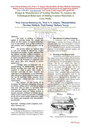
The purpose of our testing is to There are four main sealing points within an
investigate the tribological properties of several end face mechanical seal (Fig. 2.1). The primary
low-friction ,sliding contact materials in contact seal is at the seal face, Point A. The leakage path
with each other in order to determine their at Point B is blocked by an O-ring, a V-ring or a
usefulness for different applications. All tests wedge. Leakage paths at Points C and D are
were performed using our testing machine to blocked by gaskets or O-rings.
measure dynamic coefficient of friction. Results
will be used to evaluate the potential of materials
for the use in various similar applications, where
low friction and acceptable wear characteristics
are desirable.
Keywords – Tribology, surface roughness, wear,
micro- structure, etc.
Problem Definition: -
To Design & Manufacture a testing machine to
analyse the tribological behaviour of sliding contact
materials at well known Pvt Ltd Company in Pune .
Fig.1 - Sealing Points for Mechanical Seal
947 | P a g e
2. Prof. Chavan Dattatraya K., Prof. S. N. Satpute, Dhandal Rohit, Devidan Mithlesh, Patil Pankaj,
Balhara Neeraj / International Journal of Engineering Research and Applications (IJERA)
ISSN: 2248-9622 www.ijera.com Vol. 2, Issue 4, July-August 2012, pp.947-953
The faces in a typical mechanical seal 2. The fluid sealed has caused the dynamic O-
are lubricated with a boundary layer of gas or ring to swell.
liquid between the faces. In designing seals for 3. The temperature limit of the dynamic O-
the desired leakage, seal life, and energy ring has been exceeded and the O-ring has
consumption, the designer must consider how the lost its elasticity (compression set) or
faces are to be lubricated and select from a become hard.
number of modes of seal face lubrication. 4. Spring compression is inadequate because
To select the best seal design, it's of incorrect installation.
necessary to know as much as possible about the 5. Solids in the stuffing box, gasket
operating conditions and the product to be sealed. protrusion or other foreign material restrict
Complete information about the product and the motion of dynamic seal ring.
environment will allow selection of the best seal
for the application.
1. PROBLEMS WITH MECHANICAL 1.4 Thermal degradation of Mechanical Seal 0-
SEALS rings
1. 1 Failure of Mechanical Seals-
O-rings are the one part of a mechanical seal that
are sensitive to heat because of the way they are
Mechanical Seals failures because of four manufactured. The ingredients are mixed together,
broad categories- put in a mould and cured at high temperature for a
specific time. The compound will then assume the
• The seal motion was restricted and the faces shape of the mould and its hardness will increase.
opened. When the O-ring is placed in an O-ring groove in a
seal and heated to a temperature beyond its
• Heat caused the O-rings to deteriorate. recommended limit, the curing process will continue
and the O-ring will take a compression set. This
• The seal materials were attacked by the fluid means that the O-ring has lost some of its resilience
sealed. and squeeze, and fluid may leak past the O-ring. The
higher the temperature, the shorter the time before
the O-ring takes a compression set. When an O-ring
• The seal was installed incorrectly. is exposed to high temperature for a long period, it
will become hard and brittle, causing mechanical
1.2 Mechanical Seals motion restricted seals failure.
The spring-loaded (dynamic) seal face 1.5 Since heat is often a problem and seldom
constantly moves to maintain full face contact with helps the mechanical seal application, what can
the stationary seal face. The main reasons for this be done about it ?
movement are 1. Use a balanced seal to minimize the heat
generated by the seal.
1. The stationary face is not perpendicular to 2. Use low-friction face materials. Carbon vs
the pump shaft.. silicon carbide is the best choice.
2. The pump has bearing end play. This 3. Use a clean liquid flush or product
means that the shaft moves back and forth a recirculation to carry away heat.
few thousands of an inch at frequent but 1.6 Mechanical Seal materials attacked
random intervals. When the correct materials are not selected,
3. There is some impeller unbalance causing 1. The 0-rings may swell locking up the
shaft whip. mechanical seal,
4. The pump is operated away from its BEP, 2. The mechanical seal faces may deteriorate
causing side loads on the shaft. rapidly, and
5. There is thermal shaft growth and Pump 3. The metal seal components may corrode.
vibration that affects the seal. All can cause the mechanical seals to fail.
1.7 Mechanical seals installed incorrectly
1.3 Here are the major conditions that can Many mechanical seals fail at initial start-up or
restrict movement of the spring loaded prematurely because they were not installed
mechanical seals face correctly. Cartridge seals eliminate all measurement,
protect the seal faces from contamination and are
easy to install. With these seals, installation
1. Solids have collected in the seal or around
problems are minimized. The Outside seal is preset
the dynamic seal ring.
948 | P a g e
3. Prof. Chavan Dattatraya K., Prof. S. N. Satpute, Dhandal Rohit, Devidan Mithlesh, Patil Pankaj,
Balhara Neeraj / International Journal of Engineering Research and Applications (IJERA)
ISSN: 2248-9622 www.ijera.com Vol. 2, Issue 4, July-August 2012, pp.947-953
and requires no installation measurement. Only in-
line seals require careful measurement to insure
correct installation. By following the mechanical
seals installation instructions, step-by-step correct
seal installation is easily achieved.
2. MANUFACTURED
COMPONENTS OF MACHINE
Assembled Seal Assembly
Housing
Gland
Disassembeled Seal Assembly
Actual Manufactured Testing Machine
Fig. 2 – Various components of machine
Seal Face 3. PROJECT:- TRIBOLOGICAL
EVALUATION OF SLIDING
FACES
949 | P a g e
4. Prof. Chavan Dattatraya K., Prof. S. N. Satpute, Dhandal Rohit, Devidan Mithlesh, Patil Pankaj,
Balhara Neeraj / International Journal of Engineering Research and Applications (IJERA)
ISSN: 2248-9622 www.ijera.com Vol. 2, Issue 4, July-August 2012, pp.947-953
2. SIC- Carbon
3. SIC- Ceramic
4. SIC- SIC
5. Carbon- SS-316
6. TC- Carbon
7. Ceramic- TC
8. Carbon- Carbon
9. SIC- SS-316
10. Ceramic- Carbon
11. SS-316 – TC
12. Ceramic- SS-316
Due to the limited number of sliding contact
materials, we could make only 12 possible
combinations for testing.
5. OBSERVATION TABLE
{ }
Curre
Temp nt Ti
S Material Materia
( ) (Amp me
r. -1 l-2
(Initia ) (mi
N (Station (Rotary
l= (Initia n)
o. ary) )
31) l=
0.8)
Tungste
Ceramic
1 n 36 0.8 10
Carbide
(width
(width
Before
2 Before 41 0.8 10
Test):-
Test):-
11.075m
11.245
m
3 mm 44 0.7 10
11.065m
11.258
m
mm
Fig.3 – CAD diagram 11.054m
11.270
4 m 47 0.7 10
mm
11.071m
11.261
m
mm
5 (width 49 0.7 10
(width
After
After
Test):-
Test):-
11.067m
11.251
m
mm
11.071m
11.269
6 m 49 0.7 10
mm
11.064m
11.255
m
mm
11.061m
11.245
m
mm
5.1 Note: - (All readings are taken at constant
pressure = 10 bar.)
The values of temperature and current are noted
down after 10 mins interval and the procedure is
repeated for 12 possible combinations mentioned
4. TESTING AND ANALYSIS above.)
List of Combinations 5.2 Calculations for Coefficient Of Friction
For the case of SIC-TC
1. SIC- TC As P=V*I
950 | P a g e
5. Prof. Chavan Dattatraya K., Prof. S. N. Satpute, Dhandal Rohit, Devidan Mithlesh, Patil Pankaj,
Balhara Neeraj / International Journal of Engineering Research and Applications (IJERA)
ISSN: 2248-9622 www.ijera.com Vol. 2, Issue 4, July-August 2012, pp.947-953
Where, P = Power given by motor 5.4 Table for Wear
V = Rated voltage of motor
I = Average Current consumed by Test Material 1 Material 2
machine no.
= 415*1.1 1 Name SIC Carbon
= 456.5 VA Wear 0.0005mm 0.0035mm
P = 0.6119 HP (Since 1HP = 746 2 Name Ceramic TC
W) wear 0.013 0.01775
As 3 Name Carbon Carbon
HP= [2 π nT] /4500 Wear 0.0025mm 0.037275mm
0.6119 = [2 * 3.14 * 1400 * T]/4500
4 Name Carbon SS 316
T = 0.3127 Kgf- m
Wear 0.0255mm 0.0015mm
As
T=F*r 5 Name Ceramic Carbon
0.3127 = F * 0.025 Wear 0.0045mm 0.0035mm
F = 12.508 Kgf 6 Name TC Carbon
F1 = 7.32 Kgf (spring load) Wear 0.00425mm 0.001mm
F2 = P * Circumferential area were force is 7 Name SIC SS 316
being applied by water Wear 0.002mm 0.005mm
F2 = 10 * 3.14 (222 – 152) 8 Name SIC TC
F2 = 8132.6 Kgf Wear 0.0165mm 0.006mm
As 9 name SIC Ceramic
Coefficient of friction = Force Wear 0.0995mm 0.01275mm
applied/Normal reaction 10 Name SIC SIC
Wear 0.00725mm 0.00025mm
= F / (F1+ F2)
= 12.508 / (7.32+8132.6) 6. PROFILE MICROSRTUCTURE
= 0.0015
(CERAMIC & TC)
Therefore, Coefficient of friction = 1.5 x 10⁻³
It is to be noted that, the microstructures of
Similar coefficient of friction is calculated for all
12 possible combinations are observed under the
possible combinations.
Scanning – Tunnelling microscope before and after
the test.
5.3 Table for coefficient of friction and
Fig shows the microstructures of Ceramic and
temperature rise
Tungsten Carbide combination before and after the
test.
Test Material 1 Material Temp Coefficie
. No (Stationar 2 rise in nt of
y) (Rotatin 1 hr in Friction
g) degree x 10 (-3)
Celsius
1 SIC Carbon 03 0.837
2 ceramic TC 18 1.041
3 Carbon Carbon 18 1.113
4 Carbon SS 316 12 1.12
5 Ceramic Carbon 14 1.14
6 TC Carbon 10 1.32
7 SIC SS 316 10 1.48
8 SIC TC 5 1.5
9 SIC SIC 18 1.621
10 SIC Ceramic 35 1.641
11 SS 316 TC Leakag Leakage
e
12 Ceramic SS 316 leakag leakage
e
Fig 4 - Ceramic Fig 5 -
Tungsten Carbide
(Before Test) (Before Test)
951 | P a g e
6. Prof. Chavan Dattatraya K., Prof. S. N. Satpute, Dhandal Rohit, Devidan Mithlesh, Patil Pankaj,
Balhara Neeraj / International Journal of Engineering Research and Applications (IJERA)
ISSN: 2248-9622 www.ijera.com Vol. 2, Issue 4, July-August 2012, pp.947-953
Fig 8.2.3 TC before test
Ra value=0.0958µm
Fig 8.2.4 TC after test
Ra value=0.0917µm
Fig 6 - Ceramic Fig 7 - Tungsten
Carbide
(After Test)
(After Test)
Fig 10 - Tungsten Carbide Fig 11 - Tungsten
Carbide
7. SURFACE ROUGHNESS
(Before Test) (After Test)
Ra value=0.0958µm Ra
value=0.0917µm
7.1 Note: - The graphs of 12 possible
combinations are dawn with the help of surface
roughness tester, before and after the test.
Fig 8, 9, 10, 11 shows the graphs of
Ceramic and Tungsten Carbide combination
before and after the test.
8. FUTURE SCOPE
The following modifications can be done in this
machine.
These are as follows: 1) Automation with sensor
2) Different lubricants
3) Mixture of liquids
1. The measured quantities like pressure,
temperature, current can be viewed directly
on display with the help of sensors.
2. In our testing we used water as lubricant,
Fig 8 – Ceramic (Before Test) Fig 9 – but other lubricants can be used without
Ceramic (After Test) much modification.
Ra value=0.6635µm Ra value=0.1453µm 3. With the help of two tanks different
mixtures of liquids can be stored and used
i.e. testing with hot and cold liquid is also
possible.
9. CONCLUSION
Coefficient of friction is our main
parameter of concern so we have selected the three
952 | P a g e
7. Prof. Chavan Dattatraya K., Prof. S. N. Satpute, Dhandal Rohit, Devidan Mithlesh, Patil Pankaj,
Balhara Neeraj / International Journal of Engineering Research and Applications (IJERA)
ISSN: 2248-9622 www.ijera.com Vol. 2, Issue 4, July-August 2012, pp.947-953
pairs which were having the lowest coefficient of As far as the cost factor is concerned these
friction amongst the twelve pairs. Those are: seal faces are used at such places were its
(i) SIC-Carbon cost is just equal to the cost of 0.1% of the
(ii) Ceramic-TC whole project. So cost is not a big issue
(iii) Carbon-Carbon during the use of this seal faces only the
importance is of safety of its working and
Surfac Surfac
which is ensured by all the properties
e e
Coefficien mentioned in the above table.
Rough Micros Wear
Sr. Combin t
ness tructur in Hence, by our observations and calculations
No. ations Of we can conclude that CERAMIC-TC is the
Chang e (mm)
Friction best combination possible from all the
es Chang
In µm es available combinations with us.
Due to the following facts
Low Mediu
(SIC = m (i) Low Coefficient of Friction
0.0311 (SIC = (ii) Less changes in Surface
Low
SIC – ) High 0.013) Microstructure
1. (0.837*
SS316 (-3)
10 )
(Carbo (Carbo (iii) Less changes in Surface Roughness
n= n= (iv) Lowest Wear
1.9554 0.0177
) 5) 10. BIBLIOGRAPHY
High Low
(Cera (Cera Books:
mic = - mic =
Medium
Ceramic 0.5182 Low 0.0005 1) Design Data Book of engineers ,
2. (1.041*
- TC (-3) ) ) Compiled by PSG College of
10 )
(TC =- (TC = technology
0.0041 0.0035 Coimbatore
) )
Low Mediu 2) Design of Machine Elements.
(Carbo m Tata Mc-Graw Hill Publications,
n1=- (Carbo By V.B. Bhandari
0.0042 n1=
High
Carbon- ) 0.0025 3) Design of Machine Tools
3. (1.113* Low
Carbon (Carbo )
10(-3)) Oxford and IBH Publishing Co Pvt
n2= (Carbo Ltd,
0.0394 n2= By S.K. Basu, D.K.Pal
) 0.0372
) 4) Machine Design
S.chansdPublishings
Comparison amongst the top three By R.S. Khurmi
combinations
From the above table we can see that the Websites:
coefficient of friction is minimum for 1st 1. www.eagleburgmann.com
combination but change in microstructure of
SS316 is very horrible also the surface 2. www.sealingtechnologies.com
roughness changes for SS316 is very high.
Hence, this is not a advisable combination. 3. www.uniqueseal.com/
In case of 2nd combination, though the
coefficient of friction is not as low as the 1st
combination but still its other properties are
quite good like the surface microstructure
changes of both the material is less and also
the surface roughness has not changed much
,in fact the surface roughness has decreased
that means both the materials have lapped
each other
953 | P a g e