
Recomendados
Recomendados
Mais conteúdo relacionado
Mais procurados
Mais procurados (20)
Semelhante a International Journal of Computational Engineering Research(IJCER)
Semelhante a International Journal of Computational Engineering Research(IJCER) (20)
International Journal of Computational Engineering Research(IJCER)
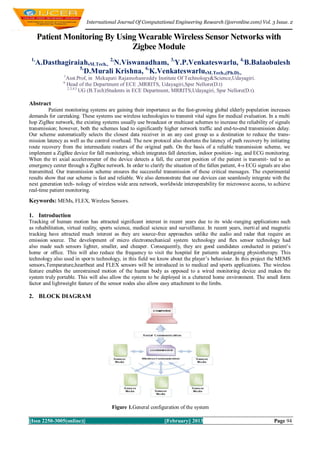
- 1. International Journal Of Computational Engineering Research (ijceronline.com) Vol. 3 Issue. 2 Patient Monitoring By Using Wearable Wireless Sensor Networks with Zigbee Module 1, A.Dasthagiraiah,M.Tech., 2,N.Viswanadham, 3,Y.P.Venkateswarlu, 4,B.Balaobulesh 5, D.Murali Krishna, 6,K.Venkateswarlu,M.Tech.,(Ph.D)., 1 Asst.Prof, in Mekapati Rajamohanreddy Institute Of Technology&Science,Udayagiri. 6 Head of the Department of ECE ,MRRITS, Udayagiri,Spsr Nellore(D.t) 2,3,4,5 UG (B.Tech)Students in ECE Department, MRRITS,Udayagiri, Spsr Nellore(D.t). Abstract Patient monitoring systems are gaining their importance as the fast-growing global elderly population increases demands for caretaking. These systems use wireless technologies to transmit vital signs for medical evaluation. In a multi hop ZigBee network, the existing systems usually use broadcast or multicast schemes to increase the reliability of signals transmission; however, both the schemes lead to significantly higher network traffic and end-to-end transmission delay. Our scheme automatically selects the closest data receiver in an any cast group as a destination to reduce the trans- mission latency as well as the control overhead. The new protocol also shortens the latency of path recovery by initiating route recovery from the intermediate routers of the original path. On the basis of a reliable transmission scheme, we implement a ZigBee device for fall monitoring, which integrates fall detection, indoor position- ing, and ECG monitoring. When the tri axial accelerometer of the device detects a fall, the current position of the patient is transmit- ted to an emergency center through a ZigBee network. In order to clarify the situation of the fallen patient, 4-s ECG signals are also transmitted. Our transmission scheme ensures the successful transmission of these critical messages. The experimental results show that our scheme is fast and reliable. We also demonstrate that our devices can seamlessly integrate with the next generation tech- nology of wireless wide area network, worldwide interoperability for microwave access, to achieve real-time patient monitoring. Keywords: MEMs, FLEX, Wireless Sensors. 1. Introduction Tracking of human motion has attracted significant interest in recent years due to its wide -ranging applications such as rehabilitation, virtual reality, sports science, medical science and surveillance. In recent years, inerti al and magnetic tracking have attracted much interest as they are source-free approaches unlike the audio and radar that require an emission source. The development of micro electromechanical system technology and flex sensor technology had also made such sensors lighter, smaller, and cheaper. Consequently, they are good candidates conducted in patient’s home or office. This will also reduce the frequency to visit the hospital for patients undergoing physiotherapy. This technology also used in spor ts technology, in this field we know about the player’s behaviour. In this project the MEMS sensors,Temparature,heartbeat and FLEX sensors will be introduced in to medical and sports applications. The wireless feature enables the unrestrained motion of the human body as opposed to a wired monitoring device and makes the system truly portable. This will also allow the system to be deployed in a cluttered home environment. The small form factor and lightweight feature of the sensor nodes also allow easy attachment to the limbs. 2. BLOCK DIAGRAM Figure 1.General configuration of the system ||Issn 2250-3005(online)|| ||February|| 2013 Page 94
- 2. International Journal Of Computational Engineering Research (ijceronline.com) Vol. 3 Issue. 2 3. Serial Communication Serial communication is basically the transmission or reception of data one bit at a time. Today's computers generally address data in bytes or some multiple thereof. A byte contains 8 bits. A bit is basically either a logical 1 or zero. Every character on this page is actually expressed internally as one byte.The serial port is used to convert each byte to a stream of ones and zeroes as well as to convert a stream of ones and zeroes to bytes. The serial port contains an electronic chip called a Universal Asynchronous Receiver/Transmitter (UART) that actually does the conversion. The serial port has many pins. We will discuss the transmit and receive pins first. Electrically speaking, whenever the serial port sends a logical one (1) a negative voltage is effected on the transmit pin.Whenever the serial port sends a logical zero (0) a positive voltage is affected. When no data is being sent, the serial port 's transmit pin's voltage is negative (1) and is said to be in a MARK state. Note that the serial port can also be forced to keep the transmit pin at a positive voltage (0) and is said to be the SPACE or BREAK state. (The terms MARK and SPACE are also used to simply denote a negative voltage (1) or a positive voltage (0) at the transmit pin respectively).When transmitting a byte, the UART (serial port) first sends a START BIT which is a positive voltage (0), followed by the data (general 8 bits, but could be 5, 6, 7, or 8 bits) followed by one or two STOP Bits which is a negative(1) voltage. The sequence is repeated for each byte sent. When transmitting a character there are other characteristics other than the baud rate that must be known or that must be setup. These characteristics define the entire interpretation of the data stream. The first characteristic is the length of the byte that will be transmitted. This length in general can be anywhere from 5 to 8 bits.The second characteristic is parity. The parity characteristic can be even, odd, mark, space, or none. If even parity, then the last data bit transmitted will be a logical 1 if the data transmitted had an even amount of 0 bits. If odd parity, t hen the last data bit transmitted will be a logical 1 if the data transmitted had an odd amount of 0 bits. If MARK parity, then thelast transmitted data bit will always be a logical 1. If SPACE parity, then the last transmitted data bit will always be a logical0. If no parity then there is no parity bit transmitted.The third characteristic is the amount of stop bits. This value in general is 1 or 2. Assume we want to send the letter 'A' over the serial port. The binary representation of the letter 'A' is 01000001. Remembering that bits are transmitt edfrom least significant bit (LSB) to most significant bit (MSB), the bit stream transmitted would be as follows for the line characteristics 8 bits, no parity, 1 stop bit and 9600 baud. LSB (0 1 0 0 0 0 0 1 0 1) MSB. The above represents (Start Bit) (Data Bits) (Stop Bit). To calculate the actual byte transfer rate simply divide the baud rate by the number of bits that must be transferred for each byte of data.In the case of the above example, each character requires 10 bits to be transmitted for each character. As such, at9600 baud, up to 960 bytes can be transferred in one second. The above discussion was concerned with the "electrical/logical" characteristics of the data stream. We will expand the discussion to line protocol. Serial mmunication can be half duplex or full duplex. Full duplex communication means that a device can receive and transmit data at the sametime. Half duplex means that the device cannot send and receive at the same time. It can do them both, but not at the same time. Half duplex communication is all but out-dated except for a very small focused set of applications. Half duplex serial communication needs at a minimum two wires, signal ground and the data line. Full duplex serial communication needs at a minimum three wires, signal ground, transmit data line, and receive data line.These signals are the Carrier Detect Signal (CD), asserted by modems to signal a successful connection to another modem, Ring Indicator (RI), asserted by modems to signal the phone ringing, Data Set Ready (DSR), asserted by modems to show their presence, Clear To Send (CTS), asserted by modems if they can receive data, Data Terminal Ready (DTR), asserted by terminals to show their presence, Request To Send (RTS), asserted by terminals if they can receive data. The section RS232 Cabling describes these signals and how they are connected. The above paragraph alluded to hardware flowcontrol. Hardware flow control is a method that two connected devices use to tell each other electronically when to send or when not to send data. A modem in general drops (logical 0) its CTS line when it can no longer receive characters. Note that hardware flow control requires the use of additional wires. The benefit to this however is crisp and reliable flow control. Another method of flow control used is known as software flow control. This method requires a simple 3 wire serial communication link, transmit data, receive data, and signal ground. If using this method, when a device can no longer receive, it will transmit a character that the two devices agreed on. This character is known as the XOFF character. This character is generally a hexadecimal 13. When a device can receive again it transmits an XON character that both devices agreed to. This character is generally a hexadecimal 11. 4. Flex Sensor The Flex Sensor patented technology is based on resistive carbon elements. As a variable printed resistor, the FlexSensor achieves great form-factor on a thin flexible substrate. When the substrate is bent, the sensor produces a resistance output correlated to the bend radius—the smaller the radius, the higher the resistance value. Flex sensors are sensors that change in resistance depending on the amount of bend on the sensor. They convert the change in bend to electrical resistance- the more the bend, the more the resistance value. They are usually in the form of a thin strip from 1"-5" long that vary in resistance from approximately 10 to 50 kilo ohms. They are often used in gloves to sense finger movement. 4.1. Attributes of FLEX Sensors Custom designed to match customer specs High level of reliability, consistency, repeatability ||Issn 2250-3005(online)|| ||February|| 2013 Page 95
- 3. International Journal Of Computational Engineering Research (ijceronline.com) Vol. 3 Issue. 2 Harsh temperature resistance Variety of flexible or stationary surfaces for mounting Infinite number of resistance possibilities and bend ratios 5. Mems Micro-Electro-Mechanical Systems (MEMS) is a new technology that has been growing by leaps and bounds recently. MEMS are the incorporation of mechanical elements, sensors, actuators, and electronics onto a common silicon base through the use of micro fabrication technology. This technology has expanded the conventional two-dimensional design of chips; it is now possible to build three-dimensional structures into the silicon wafer. The purpose of all this is to give the ability to put an entire system onto a single chip. 5.1 Benefits of MEMS Because of the increase in micromachining technology, hundreds of MEMS can be made from a single 8-inch wafer of silicon. Below is an image (Figure 2.2) which shows how small MEMS are in comparison to a dime. Because an entire system can be made this small and in such quantities, prices are reduced for products which incorporate this technology. MEMS also have no moving parts, so they are much more reliable than a macro system. Because of the reduced cost and increased reliability, there is almost no limit to what MEMS can be used for. 6. Microchip Mplab Ide MPLAB Integrated Development Environment (IDE) is a free, integrated toolset for the development of embedded applications employing Microchip's PIC® and dsPIC® microcontrollers. MPLAB IDE runs as a 32-bit application on MS Windows®, is easy to use and includes a host of free software components for fast application development and super - charged debugging. MPLAB IDE also serves as a single, unified graphical user interface for additional Microchip and third party software and hardware development tools. Moving between tools is a snap, and upgrading from the free software simulator to hardware debug and programming tools is done in a flash because MPLAB IDE has the same user interface for all tools.The MPLAB IDE software brings an ease of software development previously unseen in the 8/16 -bit microcontroller market. The MPLAB IDE is a Windows® based application that contains: An interface to debugging tools simulator programmer (sold separately) emulator (sold separately) in-circuit debugger (sold separately) A full-featured editor with colour coded context A multiple project manager Customizable data windows with direct edit of contents High level source code debugging ||Issn 2250-3005(online)|| ||February|| 2013 Page 96
- 4. International Journal Of Computational Engineering Research (ijceronline.com) Vol. 3 Issue. 2 The MPLAB IDE allows you to: Edit your source files (either assembly or C) One touch assemble (or compile) and download to PIC micro emulator and simulator tools Debug using: source files (assembly or C) absolute listing file (mixed assembly and C) machine code MPLAB IDE supports multiple debugging tools in a single development paradigm, from the cost effective simulators, through low cost in-circuit debuggers, to full-featured emulators. This eliminates the learning curve when upgrading to tools with increasing flexibility and power. 7. Experimental Results Figure shows the experimental set up of the project. The transmitter and the receiver sections are connected to PC. The MEMS sensor and the FLEX sensor are connected to the transmitter, transmits the sensed data. Receiver is connected to the COM port of the computer. It receives the data and sends to the PC via RS232 cable. Figure 3: Experimental Set up The MEMS sensor shown in figure 3.1 is attached to the forearm of the human as shown in figure 3.2 The FLEX sensor is attached to the fingers of the human as shown in figure 3.3 These sensors senses the movements of forearm and the fingers of the human and corresponding analog values are send to the microcontroller. Figure 3.1: MEMS Sensor ||Issn 2250-3005(online)|| ||February|| 2013 Page 97
- 5. International Journal Of Computational Engineering Research (ijceronline.com) Vol. 3 Issue. 2 Figure 3.2: MEMS Sensor attached to the human The on chip ADC of the PIC microcontroller converts the analog value to Digital and sends to the RF transceiver which is then transmitted to the receiver. The receiver receives the data and sends it to the microcontroller which is then serially transmitted to the PC. The data is displayed on the PC with the help of hyper terminal. As the movements of forearm and fingers of human changes, the corresponding values are displayed on the PC as shown in the figure. Figure 3.4: Results displayed on PC ||Issn 2250-3005(online)|| ||February|| 2013 Page 98
- 6. International Journal Of Computational Engineering Research (ijceronline.com) Vol. 3 Issue. 2 8. Future Scope An ambulatory and unrestrained measurement system based on a wearable wireless sensor network for tracking the human arm motion in the sagittal plane has been proposed. The wireless feature enables the unrestrained motion of the human body as opposed to a wired monitoring device and makes the system truly portable. This allows the system to bedeployed in a cluttered home environment. The small form factor and lightweight feature of the sensor nodes also allow easy attachment to the limbs.As compared with other existing approaches, the new system is portable and easy to use. It allows the patients to be monitored without restraint, and rehabilitation can be carried out in a home environment instead of a specializedlaboratory in the hospital. For future work, experiments conducted with stroke patients in collaboration with a hospital are being planned using the developed system. More tests can also be conducted to investigate the effect of RF interference from other patient monitoring devices and wireless systems. REFERENCES [1]. H. Zhou and H. Hu, ― ―Human motion tracking for rehabilitation—A survey‖Biomed. Signal Process. Control, vol. 3, no.1 pp.1–18, Jan. 2008. [2]. J.M. Zheng, K.W. Chan, and I. Gibson, ―‖Virtual reality‖ IEEE Potentials, vol. 17, no. 2, pp. 20–23, Apr. 1998. [3]. D. Jack, R. Boian, A. S. Merians, M. Tremaine, G. C. Burdea, S. V. Adamovich, M. Recce, and H. Poizner, ―Virtual reality -enhanced stroke rehabilitation,‖IEEE Trans. Neural Syst. Rehabil. Eng., vol. 9, no. 3, pp. 308–318, Sep. 2001. [4]. D. Fitzgerald, J. Foody, D. Kelly, T. Ward, C. Markham, J. McDonald, and B. Caulfield, ―Development of a wearable motion capture suit and virtual reality biofeedback system for the instruction and analysis of sports rehabilitation exercises‖, in Proc.29th Annu. Int. Conf. IEEE EMBS, 2007, pp. 4870–4874. [5]. T. B.Moeslund, A. Hilton, and V. Krüger, ―A survey of advances in visionbased human motion capture and analysis,‖ Comput.Vis. Image Underst. A.Dasthagiraiah Was Born in Seetharamapuram ,Nellore, A.P. ,INDIA., in 1988 and Received The B.Tech. (Hons) degree in Electronics And Communication Engineering From the JNTUA in 2009 and the M..Tech degree from the Hindustan University , Chennai, INDIA., in 2011 respectively. His research interests include Embedded Systems and Communication Therory. He Presently working as an Assistant Professor in MeRITS ,Udayagiri, Since 2011. N.Viswanadham Was Born in Tirupathi, A.P. ,INDIA., in 1992 and He is Studying B.Tech in Electronics And Communication Engineering ,MeRITS,Udayagiri. Y.P.Venkateswarlu Was Born in Nellore, A.P. ,INDIA., in 1991 and He is Studying B.Tech in Electronics And Communication Engineering ,MeRITS,Udayagiri. B.Balaobulesh was Born in Seetharamapuram ,A.P.,INDIA ,In 1992 and he is studying B.Tech in Electronics and Communication Engineering ,MeRITS,Udayagiri. D.Murali Krishna was Born in Kadapa ,A.P.,INDIA ,In 1992 and he is studying B.Tech in Electronics and Communication Engineering ,MeRITS,Udayagiri. ||Issn 2250-3005(online)|| ||February|| 2013 Page 99